A Practical Fast Parallel Routing Architecture for Clos Networks S.Q. Zheng
Ashwin Gumaste
Enyue Lu
Dept. of Computer Science University of Texas at Dallas Richardson, TX 75083, USA
School of Information Tech. Indian Institute of Technology Bombay, India
Dept. Math and CS Salisbury University Salisbury, MD 21801, USA
[email protected]
[email protected]
[email protected]
ABSTRACT Clos networks are an important class of switching networks due to their modular structure and much lower cost compared with crossbars. For routing I/O permutations of Clos networks, sequential routing algorithms are too slow, and all known parallel algorithms are not practical. We present the algorithm-hardware codesign of a unified fast parallel routing architecture called distributed pipeline routing (DPR) architecture for rearrangeable nonblocking and strictly nonblocking Clos networks. The DPR architecture uses a linear interconnection structure and processing elements that performs only shift and logic AND operations. We show that a DPR architecture can route any permutation in rearrangeable√nonblocking and strictly nonblocking Clos networks in O( N ) time. The same architecture can be used to carry out control of any group of connection/disconnection √ requests for strictly nonblocking Clos networks in O( N ) time. Several speeding-up techniques are also presented. This architecture is applicable to packet and circuit switches of practical sizes. Categories and Subject Descriptors: B.4.3 [Interconnections]: Parallel I/O; C.2.6 [Internetworking ]: Routers General Terms: Algorithms; Design Keywords: Clos network, circuit switching, packet switching, permutation routing, rearrangeable nonblocking, strictly nonblocking, parallel algorithm, parallel architecture, pipelining.
1.
INTRODUCTION
Switching networks serve as the core of network switches and routers, and the communication subsystems in highperformance parallel computer systems. An N × N switching network simultaneously connects up to N input/output pairs, which form a (partial) I/O permutation, using linkdisjoint (or conflict-free) paths within the network. A switching network is strictly nonblocking if there always exists a connection path from any idle input to any idle output
Permission to make digital or hard copies of all or part of this work for personal or classroom use is granted without fee provided that copies are not made or distributed for profit or commercial advantage and that copies bear this notice and the full citation on the first page. To copy otherwise, to republish, to post on servers or to redistribute to lists, requires prior specific permission and/or a fee. ANCS’06, December 3–5, 2006, San Jose, California, USA. Copyright 2006 ACM 1-59593-580-0/06/0012 ...$5.00.
in the presence of existing connections, regardless of how the existing connection paths were selected. A switching network is rearrangeable nonblocking if connections for any (partial) I/O permutation can be established under the condition that rearrangement of existing connections is allowed. Strictly nonblocking switching networks are suitable to be used as switches in circuit switching networks, whereas rearrangeable nonblocking networks are more cost-effective for implementing packet switches for packet switching networks. The routing problem of a nonblocking switching network is to find conflict-free paths for I/O permutations. The focus of this paper is on the design and analysis of a practical fast parallel architecture for routing permutations in rearrangeable and strictly nonblocking Clos switching networks[6]. A 3-stage N × N Clos network can be constructed from smaller crossbar switches arranged in three stages so that it can be rearrangeable nonblocking or strictly nonblocking depending on the number of middle-stage modules. Its cost, measured by the number of crossing points, is O(N 1.5 ), which is significantly less than that of an N × N crossbar. Due to its modular structure, the generalized Clos networks can be recursively constructed with more than three stages and cost lower than O(N 1.5 ) [3]. However, unlike crossbars for which routing is trivial, the routing problem for Clos networks is time consuming. The best known sequential algorithm for rearrangeable Clos network has time complexity O(N log N ) [15]. For strictly nonblocking Clos networks, we have not seen any algorithm that routes O(N ) new connections in the presence of O(N ) existing connections in less than O(N 1.5 ) time in the worst case. In order to speed up routing, parallel algorithms must be used. For rearrangeable 3-stage Clos networks, the best parallel time complexity is O(log 2 N ) if the number of middle stage modules is a power of 2 [8]. This result is also reported in [11, 12] in different forms. For an arbitrary number of middle stage modules, the best parallel time known is O(log 3 N ) according to [8]. These parallel time complexities are derived on the abstract parallel random access machine (PRAM) model [9] or a completely connected multiprocessor system of N processors supporting constant time communications of complicated patterns, which are either unrealistic or too expensive to build. We have not seen practical fast parallel algorithms for routing an arbitrary set of connections in strictly nonblocking Clos networks. In this paper, we present the algorithm-hardware codesign of a fast parallel routing architecture called distributed pipeline routing (DPR) architecture. We first present a unified PRAM algorithm for routing in rearrangeable and
strictly nonblocking Clos networks, and then describe the DPR architecture that directly implements this algorithm. The attractive features of the DPR architecture include its simplicity and very small constant associated with its time complexity. It uses a linear interconnection structure and O(N ) processing elements that performs only shift and logic AND operations. A permutation routing task is decomposed into groups of simple Boolean logic operations, and these operations are distributed over processing elements in a pipelined fashion. Pipelining is further utilized at different levels to improve performance. We show that a DPR architecture can route any permutation in rearrangeable √ nonblocking and strictly nonblocking Clos networks in O( N ) time. The same architecture can be used to carry out control of any group of connection/disconnection requests for √ strictly nonblocking Clos networks in O( N ) time. Several speeding-up techniques are also presented. Considering that √ N ≤ log22 N for N ≤ 65, 536, our architecture is applicable to packet and circuit switches of practical sizes.
2.
ROUTING IN CLOS NETWORKS
The Clos network C(n1 , r1 , m, n2 , r2 ) is an r1 ·n1 ×r2 ·n2 3stage network, where the first stage S1 consists of r1 (input) crossbars S1 (i), 0 ≤ i ≤ r1 − 1, of size n1 × m, the last stage S3 consists of r2 (output) crossbars S3 (j), 0 ≤ j ≤ r2 − 1, of size m × n2 , and the middle stage S2 has m crossbars S2 (k), 0 ≤ k ≤ m − 1, of size r1 × r2 . Each input crossbar S1 (i) has a connection to each middle stage crossbar S2 (k). Similarly, each middle stage crossbar S2 (k) has a connection to each output crossbar S3 (j). Each component crossbar is called a module. Figure 1 shows the structure of C(n1 , r1 , m, n2 , r2 ). 0
r1 ✕ r2
0
.. .
n 1✕ m 1
.. .
n 1✕ m
.. . .. .
n 1✕ m
r1 ✕ r2 2
.. .
m ✕ n2
.. .
m ✕ n2
r1 ✕ r2
2
.. .
1
0
.. .
n 1✕ m
.. .
m ✕ n2
.. .
. . .
r1 -1
.. .
1
2
.. . . . .
. . .
.. .
m-1
.. .
m ✕ n2
.. .
r1 ✕ r2
S1
S2
0,0 0,1
. . .
.
.
S 3(0)
.
S 1(0) 0,n-1
0,0 0,1
.
.
.
S 2(2n-2) . . . . . .
n-1,0 n-1,1
n-1,0 n-1,1
S 1(n-1)
. . .
S 3(n-1)
S2
S3
S 2(0) n-1,n-1
S1
. . .
n-1,n-1
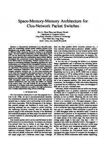
Figure 2: A 3-dimensional view of C(n, 2n − 1, n). For C(n, m, r), the N = nr inputs are denoted by a set I = ∪0≤i≤r−1 IGi , where IGi = {Ii,k |0 ≤ k ≤ n − 1} is the i-th input group that consists of inputs of input module S1 (i), with Ii,k being the k-th input of S1 (i). Similarly, the set of N outputs is O = ∪0≤j≤r−1 OGj , where OGj = {Oj,k |0 ≤ k ≤ n − 1} is the j-th output group, which consists of outputs of output module S3 (j), with Oj,k being the kth output of S3 (i). The connections between I and O of C(n, m, r) can be characterized by a mapping π from I to O. For a (partial) permutation, each input in I is to be connected to at most one output in O and each output in O is to be connected to at most one input in I. We represent I/O connections by a bipartite graph G(V1 , V2 ; E), which has r nodes in each of V1 and V2 , and a set E of edges between V1 and V2 . More specifically, the nodes in V1 are labeled vi0 (for input group IGi ) and the nodes in V2 are labeled vj00 (for output group OGj ), 0 ≤ i, j ≤ r − 1. There is a one-to-one correspondence between each I/O connection in an I/O mapping π and an edge in E: the I/O connection from Ii,j to Op,q is corresponding to an edge between node vi0 and node node vp00 . Clearly, G(V1 , V2 ; E) is a multigraph of degree at most n. We denote the set of edges in E that connect the same pair of nodes vi0 and vj00 by Ei,j , i.e. Ei,j = {e|e = (vi0 , vj00 ) ∈ E}. We call G(V1 , V2 ; E) an I/O mapping graph. Example 1. Consider the following I/O mapping:
r2 -1
.. .
and strictly nonblocking C(n, m, r)s with m = O(n) have O(N 1.5 ) crossing points. Figure 2 gives a 3-dimensional view of C(n, 2n − 1, n), where each module is represented by a plane.
S3
Figure 1: Three-stage Clos network C(n1 , r1 , m, n2 , r2 ).
When n1 = n2 = n and r1 = r2 = r, the network C(n1 , r1 , m, n2 , r2 ) is called a symmetric 3-stage Clos network, denoted by C(n, m, r). We are particularly interested in N × N symmetric Clos networks C(n, m, r), where N = nr. It is known that C(n, m, r) is rearrangeable nonblocking if and only if m ≥ n [1] and C(n, m, r) is strictly nonblocking if and only if m ≥ min{2n − 1, nr} [6]. Thus, rearrangeable
„
(0, 0)∗ (0, 2)∗
(1, 4) (0, 1)
(0, 3) (2, 4)
(2, 0)∗ (4, 0)∗
(1, 0) (4, 1)
(2, 4)∗ (3, 0)∗
(1, 1) (3, 3) (3, 1)∗ (2, 2)∗
(1, 2) (0, 3)
(1, 3) (1, 2)
(4, 1)∗ (3, 2)∗
(4, 2) (3, 4)
«
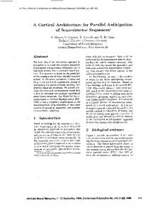
in which (x, y) and (x0 , y 0 ) in the same column indicates input Ix,y is mapped to output input Ox0 ,y0 in strictly nonblocking C(5, 9, 5). A column marked with ∗ corresponds to an existing I/O connection and a column without ∗ indicates a new connection to be established. The corresponding I/O mapping graph is shown in Figure 3. For routing in rearrangeable nonblocking C(n, m, r) used as a cell switch, no connection is assumed existing.
v’0
(00,02)
color 0
(03,24)
(14,01)
v’’0
color 1 color 8
(12,03) (13,12)
v’1
color 3
v’’1
(11,33) (10,41)
v’2
color 4
(24,30)
v’’2
color 2
(20,40)
v’3
(31,22) color 5
color 2
v’’3 color 7
(42,34) color 6
v’4
(41,32)
v’’4
Figure 3: An I/O mapping graph of strictly nonblocking C(5, 9, 5), where a solid edge corresponds to an existing I/O connection, and a dashed edge corresponds to an I/O connection to be established. (xy, x0 y 0 ) is a connection from Ix,y to Ox0 ,y0 .
The routing problem for C(n, m, r) can be solved by properly coloring edges of G(V1 , V2 ; E) with at most m colors. We say that the edges are properly colored if no two edges incident at the same node have the same color. A proper coloring of edges in G(V1 , V2 ; E) translates into conflict-free I/O connections within C(n, m, r) as follows: if an edge between vi0 and vj00 is assigned color k, then its corresponding I/O connection is established by letting it to take the unique path through the middle stage module S2 (k). Hence, we can reduce the problem of routing connections in C(n, m, r) to the following two graph coloring problems: Weak Edge Coloring Problem: Given an I/O mapping graph G(V1 , V2 ; E), properly color edges in E. If we can find a weak edge-coloring of G(V1 , V2 ; E) using at most c1 different colors, we call this coloring a (weak)1 c1 -edge coloring of G(V1 , V2 ; E). Strong Edge Coloring Problem: Given an I/O mapping graph G(V1 , V2 ; E) with a subset E c of properly colored edges of E, color edges in E − E c without changing the colors of edges in E c so that all edges in E are properly colored. If we can find a strong edge-coloring of G(V1 , V2 ; E) using at most c2 different colors, we call this coloring a strong c2 -edge coloring of G(V1 , V2 ; E). Note that the degree of any I/O mapping graph G(V1 , V2 ; E) of C(n, m, r) is n. Let ∆(G) denote the degree of a bipartite multigraph G. The following two lemmas guarantee that an m-edge coloring is always possible for any G(V1 , V2 ; E) of a rearrangeable nonblocking C(n, m, r), and a strong m-edge coloring is always possible for any G(V1 , V2 ; E) of a strictly nonblocking C(n, m, r). Lemma 1. [2] Every bipartite multigraph G has a ∆(G)edge coloring. Lemma 2. [12] Any multigraph G has a strong (2∆(G) − 1)-edge coloring.
3. A PARALLEL ROUTING ALGORITHM In this section, we present a parallel algorithm for edge coloring of bipartite multigraphs of degree n. This algorithm can be used to find m-edge coloring of bipartite multigraphs of degree n, where m ≥ n, and strong m-edge coloring of bipartite multigraphs of degree n, where m ≥ 2n − 1. The approach of solving routing problems by graph edge-coloring has been used extensively (e.g. [5, 7, 10, 8, 12, 14]). Unlike existing work, which aimed at finding theoretically fastest algorithms, our objective is to design a fast algorithm COLORING that is feasible for hardware implementation. There are r2 processing elements P Ei,j , 0 ≤ i, j ≤ r − 1. Let Color1[0..r − 1, 0..m − 1] be an r × m Boolean array such that Color1[i, k] = 1 if and only if color k is available for any edge incident at node vi0 in V1 . Similarly, we define Color2[0..r − 1, 0..m − 1] as an r × m Boolean array such that Color2[j, k] = 1 if and only if color k is available for any edge incident at node vj00 in V2 . As input of COLORING, we are given a bipartite multigraph G(V1 , V2 ; E) of degree n with E c being the subset of colored edges. We use Ei,j to denote the subset of edges of E with one end node incident at vi0 and the other incident at vj00 . algorithm COLORING(G(V1 , V2 ; E)) begin for k = 0 to m − 1 do for all P Ei,j , 0 ≤ i, j ≤ r − 1, do in parallel ci,j,k := (i + j + k) mod m; if there is an uncolored edge e in Ei,j and Color1[i, ci,j,k ] ∧ Color2[j, ci,j,k ] = 1 then begin select one uncolored edge e from Ei,j ; assign color ci,j,k to edge e and mark e “colored”; Color1[i, ci,j,k ] := 0; Color2[j, ci,j,k ] := 0 end end Theorem 1. Let G(V1 , V2 ; E) be any bipartite multigraph such that |V1 | = |V2 | = r and its degree is n, and E c be a subset of edges that are properly colored with no more than m colors. If m ≥ 2n − 1, then algorithm COLORING colors the edges in E uc = E − E c properly without changing the colors of edges in E c . If m ≥ n and E c = ∅, then algorithm COLORING properly colors the edges in E. Proof. The algorithm has m iterations. The proof consists of the following simple facts: (i) In iteration k, one uncolored edge, if any, in each Ei,j , 0 ≤ i, j, ≤ r − 1, is selected. Note that such a selected edge may or may not be colored in the iteration, and it is colored if and only if Color1[i, ci,j,k ] ∧ Color2[j, ci,j,k ] = 1 and the color used is (i + j + k) mod m. (ii) In iteration k, if two edges, one in Ei,j and one in Ep,q are assigned the same color, then i 6= p and j 6= q. This is because (i + j + k) mod m = (p + q + k) mod m only if i 6= p and j 6= q. (iii) For each uncolored edge, all m colors are tried.
1
The definition of weak edge-coloring is the same as the definition of edge-coloring in graph theory. Thus we omit “weak” in the rest of this paper.
(iv) After m iterations all uncolored edges are assigned colors and no two edges incident at a common node are
assigned the same color because of (i), (ii) and (iii), and Lemma 1 and Lemma 2. This completes the proof of the theorem. Using the nr-processor EREW PRAM abstract parallel machine model, each iteration of the outer for-loop of COLORING can be easily carried out in O(1) time. Similarly, using an nr-processor parallel computer system with nr processors connected as a complete graph, each iteration can be carried out in O(1) time. The total time required by COLORING is O(m). Since for C(n, m, r) to be rearrangeable nonblocking and strictly nonblocking, m ≥ n and m ≥ 2n − 1, respectively, we have the following result: Corollary 1. For an N × N rearrangeable or strictly √ nonblocking C(n, m, r) network √ with m = O(n) = O( N ), algorithm COLORING takes O( N ) time to route any I/O mapping on an N -processor EREW PRAM or a completely √ connected N -processor parallel computer system in O( N ) time. PRAM model is not realistic. A completely connected multiprocessor system requires O(N 2 ) interconnection complexity, making it unscalable and too expensive to build. In the next section, we present a parallel processing architecture for algorithm COLORING. This architecture has linear interconnection complexity and can achieve the same performance as PRAM and a completely connected N -processor parallel computer system.
4.
DISTRIBUTED PIPELINING ROUTING ARCHITECTURE
In this section, we introduce our hardware routing architecture for C(n, m, r) networks. We name our architecture as the Distributed Pipelining Routing (DPR) architecture. We consider a subclass (rearrangeable or strictly) nonblocking Clos networks C(n, m, r) such that n = r. The reason of choosing n = r is because for such networks our DPR design is optimally balanced. Our design can be extended to perform routing in nonblocking C(n, m, r) networks of arbitrary valid values of n, m and r. For brevity, we omit this extension in this paper.
where is a blank field to be filled. After routing, a 3tuple (p, j, c) is returned to Ii,p , where c corresponds to a color, indicating that a connection from Ii,p to Oj,q is going to go through middle stage module S2 (c). Note that upon receiving (p, j, c), Ii,p can make a connection from Ii,p to output Oj,q by self-routing. IPi,j is responsible for finding c for I/O pair (Ii,p , Oj,q ). We call such a 3-tuple a connection addition request token (CAR token). CAR tokens of each input group IGi flow around ring IRi in pipelined fashion. (3) Each IPi,j in ring IRi has a 1-bit cell denoted by c0i,j , a circuit capable of carrying out simple Boolean logic operations, a couple of working registers, and a small amount of memory. In IRi , the last processing element, IPi,n−1 , has m − n additional cells. A total of m cells form an m-cell ring, with 1 cell in each of the first n − 1 PEs, and m − n + 1 cells in the last PE, IPi,n−1 . This m-cell ring is called an input circular shift register (ICSR). For easy reference, we denote this m-cell ring by ICSRi . (4) Each OPi,j in ring ORi has a 1-bit cell denoted by c00i,j . The last processing element, OPi,n−1 , in ORi has m−n additional cells. A total of m cells form an m-cell ring, with 1 cell in each of the first n − 1 PEs, and m − n + 1 cells in the last PE, OPi,n−1 . This m-cell ring is called an output circular shift register (OCSR), and we denote it by OCSRi . (5) Each IPi,j is associated with a modulo-m circular counter CCi,j . Thus, there are n circular counters in each IRi , and a total of N = n2 such counters. (For convenience, we also assume that each OPi,j is associated with a modulo-m circular counter CCi,j . We denote 1 the counters for IP s as CCi,j s and counters for OP s 2 as CCi,j s.) All counters are incremented by a common system clock. The initial value of CCi,j is set (i + j) mod m. (6) Each IPi,j is connected to OPj,i by a 1-bit bidirectional link. Thus, Both IPi,j and OPj,i can access c00j,i . (7) All IP s, OP s, ICSRs and OCSRs are under the control of a common system clock.
4.1 Basic Hardware Features The design of DPR for (rearrangeable or strictly) nonblocking Clos networks C(n, m, n) is based on the structure of G(V1 , V2 ; E) and algorithm COLORING. It has the following features: vi0
(1) Corresponding to each node in V1 (i.e. each input group IGi of C(n, m, n)), there is a ring IRi of n processing elements (PEs) denoted by IPi,j , 0 ≤ j ≤ n−1. IPi,j is connected to IPi,(j−1) mod n by a unidirectional link. Similarly, there is a ring ORi of n PEs denoted by OPi,j , 0 ≤ j ≤ n−1, corresponding to each node vi00 in V2 (i.e. each output group OGi ) such that OPi,j is connected to OPi,(j−1) mod n by a unidirectional link. IRi (resp. ORi ) is called input ring (resp. output ring) i. (2) A request for connection from input Ii,p to output Oj,q is received by IPi,p . IPi,p forms a 3-tuple (p, j, ),
The architecture of input rings IRi and output rings QRj for C(5, 9, 5) are shown in Figure 4. Figure 5 shows the overall structure of our DPR architecture.
4.2 Hardware Algorithm Based on the architecture presented in the previous section, we have a hardware algorithm HARD-COLORING that implements algorithm COLORING of Section 3. The algorithm iterates continuously with each iteration consisting of three phases: algorithm HARD-COLORING begin repeat Phase 1; Phase 2; Phase 3 for ever end
We call each iteration of HARD-COLORING a routing cycle. We now present the details for each of the three phases of a routing cycle. I i,4
I i,3
I i,2
I i,1
I i,0
4.2.1 Phase 1 - Distribution of I/O Edges IPi,4
IPi,3
OP4,i
IPi,2
OP3,i
IPi,1
In IRi , IPi,j is responsible for processing all I/O connection requests from input group IGi to output group OGj . We call IPi,j the agent for I/O connections from IGi to OGj . Each I/O connection from input group IGi to output group OGj corresponds to an edge from vi0 to vj00 in the corresponding I/O mapping graph G(V1 , V2 ; E), and all CAR touc = E uc ∩Ei,j kens from IGi to OGj correspond to the set Ei,j of new edges of G(V1 , V2 ; E) to be colored (note: for reconfigurable nonblocking Clos networks, E uc = E). The purpose of this phase is to prepare CAR tokens, and distribute them to their respective agent PEs. The operations of this phase are given below:
IPi,0
OP2,i
OP1,i
OP0,i
IP2.j
IP1,j
IP0,j
(a) IP4,j
OPj,4
OPj,3
IP3,j
OPj,2
OPj,1
OPj,0
(b)
Figure 4: The input and output rings for C(5, 9, 5). (a) IRi . (b) ORj .
for all IPi,p , 0 ≤ i, p ≤ n − 1, do in parallel if Ii,p receives a request to be connected to Oj,q then prepare a CAR token (p, j, ) for k = 1 to n − 1 do for all IPi,j , 0 ≤ i, j ≤ n − 1, do in parallel if IPi,j has a CAR token (p, j 0 , ) such thatp 6= j then send (p, j 0 , ) to IPi,(j−1) mod n
4.2.2 Phase 2 - Color Assignment 1
2
C i,j sequence
C i,j sequence
0 1 2 3 4 5 6 7 8 0 ...
0,0
0,0
IR 0
OR 0
0 1 2 3 4 5 6 7 8 0 ...
0,1
0,1
1 2 3 4 5 6 7 8 0 1 ...
2 3 4 5 6 7 8 0 1 2 ...
0,2
0,2
2 3 4 5 6 7 8 0 1 2 ...
3 4 5 6 7 8 0 1 2 3 ...
0,3
0,3
3 4 5 6 7 8 0 1 2 3 ...
4 5 6 7 8 0 1 2 3 4 ...
0,4
0,4
4 5 6 7 8 0 1 2 3 4 ...
1,0
1,0
1 2 3 4 5 6 7 8 0 1 ...
1 2 3 4 5 6 7 8 0 1 ...
IR 1
OR 1
1 2 3 4 5 6 7 8 0 1 ...
1,1
1,1
2 3 4 5 6 7 8 0 1 2 ...
3 4 5 6 7 8 0 1 2 3 ...
1,2
1,2
3 4 5 6 7 8 0 1 2 3 ...
4 5 6 7 8 0 1 2 3 4 ...
1,3
1,3
4 5 6 7 8 0 1 2 3 4 ...
5 6 7 8 0 1 2 3 4 5 ...
1,4
1,4
5 6 7 8 0 1 2 3 4 5 ...
2,0
2,0
2,1
2,1
3 4 5 6 7 8 0 1 2 3 ...
4 5 6 7 8 0 1 2 3 4 ...
2,2
2,2
4 5 6 7 8 0 1 2 3 4 ...
5 6 7 8 0 1 2 3 4 5 ...
2,3
2,3
5 6 7 8 0 1 2 3 4 5 ...
6 7 8 0 1 2 3 4 5 6 ...
2,4
2,4
6 7 8 0 1 2 3 4 5 6 ...
3,0
3,0
3,1
3,1
4 5 6 7 8 0 1 2 3 4 ...
5 6 7 8 0 1 2 3 4 5 ...
3,2
3,2
5 6 7 8 0 1 2 3 4 5 ...
6 7 8 0 1 2 3 4 5 6 ...
3,3
3,3
6 7 8 0 1 2 3 4 5 6 ...
7 8 0 1 2 3 4 5 6 7 ...
3,4
3,4
7 8 0 1 2 3 4 5 6 7 ...
4,0
4,0
4,1
4,1
5 6 7 8 0 1 2 3 4 5 ...
6 7 8 0 1 2 3 4 5 6 ...
4,2
4,2
6 7 8 0 1 2 3 4 5 6 ...
7 8 0 1 2 3 4 5 6 7 ...
4,3
4,3
7 8 0 1 2 3 4 5 6 7 ...
4,4
8 0 1 2 3 4 5 6 7 8 ...
2 3 4 5 6 7 8 0 1 2 ...
2 3 4 5 6 7 8 0 1 2 ... 3 4 5 6 7 8 0 1 2 3 ...
3 4 5 6 7 8 0 1 2 3 ... 4 5 6 7 8 0 1 2 3 4 ...
4 5 6 7 8 0 1 2 3 4 ... 5 6 7 8 0 1 2 3 4 5 ...
8 0 1 2 3 4 5 6 7 8 ...
IR 2
IR 3
IR 4
4,4
OR 2
OR 3
OR 4
2 3 4 5 6 7 8 0 1 2 ...
3 4 5 6 7 8 0 1 2 3 ...
4 5 6 7 8 0 1 2 3 4 ...
time t0 t1 t2
time t0 t1 t2
Figure 5: DPR architecture for Clos network 1 C(5, 9, 5). The sequence of values of each CCi,j and 2 CCi,j is given on the left side and right side of IPi,j and OPi,j , respectively.
This phase directly implements the algorithm COLORING. Boolean circular shift registers ICSRi s (resp. OCSRi s) are used to represent array Color1 (resp. Color2), and each ICSRi (resp. OCSRi ) is used to represent subarray Color1[i, 0..m−1] (resp. Color2[i, 0..m−1]). The operations of this phase are as follows: for k = 0 to m − 1 do begin for all IPi,j , 0 ≤ i, j ≤ n − 1, do in parallel begin if c0i,j ∧ c00j,i = 1 and there is a CAR token (p, j, ) with its third field unfilled 1 then assign CCi,j value (i.e. a color number) as the value of the third field of the 1 token to obtain (p, j, CCi,j ), and set c0i,j := 0 and c00j,i := 0; increment CCi,j by 1; end for all ICSRi and all OCSRi , 0 ≤ i ≤ n − 1, do in parallel perform a circular shift operation; end
4.2.3 Phase 3 - Redistribution of I/O Edges The purpose of this phase is to move each CAR token (j 0 , p, cj 0 ,p ) in IRi at the end of Phase 2 back to IPi,j 0 , where the token originally came from in Phase 1. Suppose that a token T = (j 0 , p, cj 0 ,p ) is currently in IPi,j , and to be sent back to IPi,j 0 . We define T ’s current forward distance to its destination as j − j 0 if j 0 ≤ j, and n − j 0 + j if j 0 > j. The current forward distance of T to its destination is the minimum number of hops in IRi for T to reach its destination IPi,j . The operations of this phase are given below:
for k = 1 to n − 1 do for all IPi,j , 0 ≤ i, j ≤ n − 1, do in parallel if IPi,j has a token T such that its forward distance to its destination is k then send T to IPi,(j−1) mod n Example 2. Consider the I/O mapping and colors for existing connections in Example 1, as shown in Figure 3. For IR1 of the DPR for C(5, 9, 5), there are five connection requests: (I1,0 , O4,1 ), (I1,1 , O3,3 ), (I1,2 , O0,3 ), (I1,3 , O1,2 ), and (I1,4 , O0,1 ). In Phase 1, five CAR tokens, (0, 4, ), (1, 3, ), (2, 0, ), (3, 1, ), (4, 0, ), are prepared as shown in Figure 6(a). After Phase 1, all CAR tokens in IR1 are received by their agent IP s, and Phase 2 starts using the configuration of Figure 6(b). Colors available are 1, 3, 4, 7 and 8. Colors 0, 2, 5, and 6 can not be used. The process of Phase 2 is shown in Figure 6(c). There are 9 iterations. In the figure, two rows of numbers are associated with each iteration. The first row contains values of c0 cell, denoted by (x), or CC 1 counter and c0 cell, denoted by y(x), in IR1 . The second row contains values of the corresponding c00 cells and counters CC 2 in ORs. If there is a CAR token of empty “color” field in IP1,j , and c01,j ∧ c00j,1 = 1, the current value 1 of CC1,j is assigned to the CAR token, and both of c01,j and c00j,1 are reset to 0. In Phase 3, the filled CAR tokens are sent back to their origins as shown in Figure 6(d). Figure 3 shows that the colors assigned to the edges of new connections from IG1 do not conflict with colors of the edges of the existing connections.
(4,0,_)
(3,1,_)
(2,0,_)
(1,3,_)
(0,4,_)
IP1,4
IP1,3
IP1,2
IP1,1
IP1,0
(0,4,_)
(1,3,_)
(3,1,_)
(2,0,_) (4,0,_)
IP1,4
IP1,3
IP1,1
IP1,0
(a)
(b)
OP4,1
IP1,2 OP3,1
OP2,1
0) 3(1) 0) 3(1)
2(1) 2(0)
OP1,1
OP0,1
iteration (1) (1) (1) (1) (0) (1) (1) (0)
5(1) 5(0)
4(1 4(1 (1,3,4)
(0) (1) (1) (1) (0) (0) (1) (1)
6(1) 6(0)
5(1) 5(0)
1(1 1(1
0) 0)
0
(2,0,1)
4(0) 4(0)
3(1 3(1
0) 2(1) 0) 2(0)
1
(3,1,3)
(1) (0) (1) (1) 7(1 (0) (0) (0) (1) 7(1
0) 6(1) 0) 6(0)
5(1) 5(0)
4(0) 4(0)
3(0) 3(0)
2
(0,4,7)
(0) (1) (0) (1) (0) (0) (0) (0)
8(1) 8(1)
7(0) 7(0)
6(1) 6(0)
5(1) 5(0)
4(0) 4(0)
(0) (0) (1) (0) (0) (0) (0) (0)
0(1) 0(0)
8(1) 8(1)
7(0) 7(0)
6(1) 6(0)
5(1) 5(0)
4.3 Analysis of HARD-COLORING
(1) (0) (0) (1) (0) (0) (0) (0)
1(0) 1(0)
0(1) 0(0)
8(1) 8(1)
7(0) 7(0)
6(1) 6(0)
We show that our hardware algorithm HARD-COLORING is equivalent to algorithm COLORING of Section 3 for C(n, m, n). The following fact is obvious.
(1) (1) (0) (0) (0) (0) (0) (0)
2(1) 2(0)
1(0) 1(0)
0(1) 0(0)
8(1) 8(1)
7(0) 7(0)
(0) (1) (1) (0) (0) (1) (0) (0)
3(0) 3(0)
2(1) 2(0)
1(0) 1(0)
0(1) 0(0)
3
(c)
5
6
Fact 1. At the end of Phase 1, all CAR tokens correuc sponding to edges in Ei,j of G(V1 , V2 ; E) are sent to their agent IPi,j in pipelined fashion. Note that for rearrangeable C(n, m, n), E uc = E. 1 2 Denote the value of circular counter CCi,j and CCj,i ,0≤ i, j ≤ n − 1, during the k-th iteration of Phase 2 of HARD1 2 COLORING by CCi,j (k) and CCj,i (k), respectively. Since 1 2 1 1 CCi,j (0) = CCi,j (0) = (i + j) mod m, and CCi,j and CCi,j are incremented at the end of each iteration, the following statement is true. 1 Fact 2. Right before iteration k of Phase 2, CCi,j (k) = 2 CCi,j (k) = ci,j,k = (i + j + k) mod m, where ci,j,k is the local variable of P Ei,j in the k-th iteration of COLORING.
As noted earlier, the Boolean array Color1[0..n−1, 0..m− 1] (resp. Color2[0..n − 1, 0..m − 1]) used in algorithm COLORING is represented by ICSRi s (resp. OCSRi s), with ICSRi (resp. OCSRi ) representing subarray Color1[i, 0..m− 1] (resp. Color2[i, 0..m − 1]) for C(n, m, n). Denote the value of c0i,j and c00i,j in iteration k of HARD-COLORING by c0i,j (k) and c00i,j (k), respectively, and define that c0i,j (0) and c00i,j (0) correspond to Color1(i, ci,j,0 ) and COLOR2(i, ci,j,0 ) of iteration 0 of COLORING, respectively.
4
8(1 8(1 (4,0,8)
(0) (0) (1) (1) (0) (0) (0) (0)
4(0) 4(0)
3(0) 3(0)
2(1) 2(0)
1(0) 1(0)
0(1) 0(0)
(1) (0) (0) (1) (0) (0) (0) (0)
5(1) 5(0)
4(0) 4(0)
3(0) 3(0)
2(1) 2(0)
1(0) 1(0)
(4,0,8)
(3,1,3)
(2,0,1)
(1,3,4)
(0,4,7)
IP1,4
IP1,3
IP1,2
IP1,1
IP1,0
0) 0)
7
8
(d)
Figure 6: Operations of input ring IR1 of C(5, 9, 5) on Example 1. (a) Configuration after CAR preparation in Phase 1. (b) Configuration at the end of Phase 1. (c) Process of Phase 2. (d) Configuration after Phase 3.
Lemma 3. In iteration k of HARD-COLORING, c0i,j (k) and c00i,j (k) accessed by IPi,j correspond to Color1[i, ci,j,k ] and Color2 [j, ci,j,k ] accessed by P Ei,j in the k-th iteration of COLORING, respectively. Proof. Since the proofs for c0i,j (k) and c00i,j (k) are the same, we only consider c0i,j (k). HARD-COLORING implements COLORING for r = n. In the k-th iteration, P Ei,j in COLORING only accesses Color1[i, ci,j,k ] of array Color1. Similarly, in the k-th iteration, IPi,j in HARD-COLORING only accesses c0i,j (k) of c0 cells. By definition of c0i,j (0), the claim is obviously true for k = 0. Let J = (j + 1) mod m. Assume that the claim is true for k 0 and consider the case of iteration k 0 + 1. Let J = (j + 1) mod m. P Ei,j accesses Color1[i, ci,j,k0 +1 ], which was accessed by P Ei,J in iteration k 0 . IPi,j accesses c0i,j (k0 + 1). By the shifting operation performed at the end of iteration k 0 , c0i,j (k0 + 1) is c0i,J (k0 ), which implies that it was accessed by IPi,J in iteration k0 . By the hypothesis, c0i,j (k0 + 1) accessed by IPi,j corresponds to Color1[i, ci,j,k0 +1 ] accessed by P Ei,j in the k-th iteration of COLORING, respectively. This completes the induction. Based on Facts 1 and 2, Lemma 3 and Theorem 1, Phase 2 exactly implements algorithm COLORING. By the correctness of COLORING, Phase 2 of HARD-COLORING properly colors uncolored edges in G(V1 , V2 ; E) for C(n, m, n). Since all I/O connections considered are partial or full permutations, no two CAR tokens are destined for the same PE in each iteration of Phase 3 of HARD-COLORING in Phase 3 of HARD-COLORING. Scheduled by their forward distances, all tokens are sent back to their origins in pipelined fashion without conflict after n − 1 iterations. Let us consider the time complexity of HARD-COLORING now. Obviously, Phase 1 takes n − 1 steps, with each step taking O(1) time. Phase 2 takes m steps, with each step taking O(1) time if all tokens in each IPi,j can be found in O(1) time. This can be easily done by linking all tokens in each IPi,j as a queue in arbitrary order. While Phase 3 also takes n − 1 steps, we must ensure that each step takes O(1) time. In IPi,j , by maintaining an (n−1)-element array with its d-th element containing a pointer to the token, if any, with forward distance d, finding the token with forward distance k in the k-th iteration of Phase 3 can be done in O(1) time (note: the token with forward distance 0 remains in IPi,j in the remaining iterations of Phase 3). The total number √ of steps is 2n + m − 2. Since O(m) = O(n), where n = N for rearrangeable or strictly nonblocking C(n, m, n) networks, we have the following result: Theorem 2. For an N ×N rearrangeable or strictly non√ blocking C(n, m, n) network with m = √O(n) = O( N ), algorithm HARD-COLORING takes O( N ) steps to route any I/O mapping in one routing cycle on the DPR architecture. Since the pair IPi,j and OPj,i are connected by a link, 2 1 2 the value of CCj,i is implied by the value of CCi,j , CCj,i is redundant; its introduction is meerly for the purpose of easy analysis. To see this, consider the control architecture for C(5, 9, 5) shown in Figure 5. The sequence of values of 1 2 each CCi,j and each CCi,j s is shown on the left and right side of the figure, respectively. In the DPR architecture, routing decisions are made in parallel in different IRs and ORs. The elements of these
rings can be distributed in the input ports. The interconnection of the DPR architecture is very sparse. It is easy to see that the total number of interconnections connecting IP s and OP s in the DPR architecture for C(n, m, n) is 3N , a linear function of the inputs (or outputs).
5. ADDITIONAL FEATURES 5.1 Connection Tear-Down Algorithm HARD-COLORING finds conflict-free I/O paths for new connections in a Clos network. When an input Ii,p wants to tear down a connection for the I/O pair (Ii,p , Oj,q ), it can simply stop using its connection path. However, in order to make used internal links of C(n, m, n) by connection (Ii,p , Oj,q ) available for other connections, the current state of the network must be updated. For a rearrangeable Clos network for (slotted) packet switching, this can be done by simply setting all cells in ICSRi s and OCSRi s to 1 concurrently. For circuit switching, the situation can be more complicated if input Ii,p immediately wants to establish a connection to another output Oj 0 ,q0 after tearing down its current (Ii,p , Oj,q ) connection, and, furthermore, several inputs may want to tear down their current connections and establish new connections. We can slightly modify the three phases of algorithm HARDCOLORING to cope with such situations, making the DPR design for strictly nonblocking C(n, m, n) complete. In Phase 1, each IPi,p can prepare at most two request tokens (p, j, c)# and (p, j 0 , ), where (p, j, c)# is for deleting its current connection from Ii,p to Oj,q going through middle stage module S2 (c) (an edge in G(V1 , V2 ; E) connecting vi0 and vp00 with color c) and (p, j 0 , ) is for adding a new connection from Ii,p to Oj 0 ,q0 . We name (p, j, c)# as a connection deletion request token (CDR token). Symbol #, which can be represented by a binary bit, is used to distinguish CDR tokens from CAR tokens. There are four possibilities for each input: no CDR token and no CAR token, a CDR token but no CAR token, no CDR token but a CAR token, and a CDR token and a CAR token. Then, CDR token (p, j, c)# (if any) is sent to its agent IPi,j , and CAR token (p, j 0 , ) (if any) is sent to its agent IPi,j 0 . Tokens from all IPi,j s in IRi are sent to their destinations (agents) in pipelined fashion. Phase 2 then is modified to have two subphases. Subphase 2.1, called color erase subphase, consists of m steps as follows: for k = 0 to m − 1 do begin for all IPi,j , 0 ≤ i, j ≤ n − 1, do in parallel begin if there is a CDR token (j 0 , j, k)# and k = CCi,j then set c0i,j := 1 and c00j,i := 1 and discard token (j 0 , j, k)# ; increment CCi,j by 1; end for all ICSRi and all OCSRi , 0 ≤ i ≤ n − 1, do in parallel perform a circular shift operation; end Subphase 2.2 is color assignment subphase, which is ex-
actly the same as Phase 2 of the original HARD-COLORING. This modified algorithm has 2m + 2n − 2 steps in total. In summary, we have the following result:
IPi,4
Theorem 3. For an N ×N strictly nonblocking C(n, m, n) √ network with m = O(n) = O( N ), DPR architecture can satisfy √ any group of connection/disconnection requests in O( N ) steps.
IPi,3
OP4,i
IPi,2
OP3,i
IPi,1
IPi,0
OP2,i
OP1,i
OP0,i
(a)
5.2 Speedup of Color Erase and Color Assignment For strictly nonblocking C(n, m, n), m ≥ 2n − 1. Then, each routing cycle of the modified HARD-COLORING for C(n, 2n − 1, n) takes 6n − 4 steps. We introduce a scheme called doubled shift registers, particularly designed for strictly nonblocking C(n, 2n − 1, n), that can reduce the number of each subphases of Phase 2 to n, resulting 4n − 2 steps in a routing cycle. Instead of using one ICSRi in each IRi , we use two ICSRi s, ICSRi1 and ICSRi2 , each having n cells. Similarly, we use two n-cell OCSRi s, OCSRi1 and OCSRi2 , in each ORi . The j-th cell of ICSRi1 (resp. OCSRi1 ) and the j-th cell of ICSRi2 (resp. OCSRi2 ) reside in the same IP (resp. OP ). The j-th cell of ICSRi1 and the j-th cell of ICSRi2 are respectively connected to the i-th cell of OCSRj1 and the i-th cell of OCSRj2 . The shift operations of ICSRi1 s, ICSRi2 s, OCSRi1 s and OCSRi2 s are performed synchronously. ICSRi1 and OCSRi1 are used to maintain the availability of colors 0 through color n − 1, and ICSRi2 and OCSRi2 are used to maintain the availability of colors n through color 2n − 2. Color 2n − 1 is never used, and the values of its corresponding cells are always enforced to be 0 (i.e. unavailable). Each IPi,j has 1,1 1,2 two modulo-n circular counters CCi,j and CCi,j such that 1,2 1,1 CCi,j = (CCi,j + n) mod 2n. The modified input ring IR and output ring OR structures for C(5, 9, 5) are shown in Figures 7. For convenience, we assume that there are 2,1 2,2 two modulo-n circular counters CCi,j and CCi,j in OPi,j . For Clos network C(5, 9, 5), the sequence of values of each 1,1 1,2 2,1 2,2 (CCi,j , CCi,j ) and each (CCi,j , CCi,j ) is given on the left side and right side of IPi,j and OPi,j , respectively, in Figure 8. With this modified architecture, two pairs of cells, (ICSR1i,j , 1 2 2 OCSRj,i ) and (ICSRi,j , OCSRj,i ) can be accessed by IPi,j for color status. Thus, up to two CDR tokens and two CAR tokens can be processed by IPi,j in each step of Phase 2 of HARD-COLORING. Special digital logic circuit associated with working registers must be designed to handle different combinations of 1 and 2 tokens. In order to access two tokens stored in the memory of each IPi,j , 2-port memory or simple memory interleaving can be used. To further reduce the effective memory access time, these techniques can be combined with latency hiding, which overlaps memory access with shifting ICSRi1 s, ICSRi2 s, OCSRi1 s, and OCSRi2 s. It 1,1 1,2 2,1 is easy to verify that, by using CCi,j , CCi,j , CCi,j , and 2,2 2,1 2,2 1,1 CCi,j (where CCi,j and CCi,j are implied by CCi,j and 1,2 CCi,j , respectively) to access “colors”, this scheme reduces the number of steps used in Phase 2 by half.
5.3 Overlapping Phases A rearrangeable Clos network can be used as switching fabric in packet routers as follows. A packet received in an
IP4,j
OPj,4
IP3,j
OPj,3
IP2,j
OPj,2
IP1,j
OPj,1
IP0,j
OPj,0
(b)
Figure 7: The input and output rings with doubled shifter registers for C(5, 9, 5). (a) IRi . (b) ORj .
1,1
1,2
2,1
(C i,j , C i,j ) sequence
2,2
(C i,j , C i,j ) sequence
05 16 27 38 49 05 . . .
05 16 27 38 49 05 . . .
0,0
0,0
0,1
0,1
16 27 38 49 05 16 . . .
27 38 49 05 16 27 . . .
0,2
0,2
27 38 49 05 16 27 . . .
38 49 05 16 27 38 . . .
0,3
0,3
38 49 05 16 27 38 . . .
49 05 16 27 38 49 . . .
0,4
0,4
49 05 16 27 38 49 . . .
16 27 38 49 05 16 . . .
16 27 38 49 05 16 . . .
IR 0
OR 0
16 27 38 49 05 16 . . .
1,0
1,0
27 38 49 05 16 27 . . .
1,1
1,1
27 38 49 05 16 27 . . .
38 49 05 16 27 38 . . .
1,2
1,2
38 49 05 16 27 38 . . .
49 05 16 27 38 49 . . .
1,3
1,3
49 05 16 27 38 49 . . .
05 16 27 38 49 05 . . .
1,4
1,4
05 16 27 38 49 05 . . .
27 38 49 05 16 27 . . .
IR 1
OR 1
27 38 49 05 16 27 . . .
2,0
2,0
38 49 05 16 27 38 . . .
2,1
2,1
38 49 05 16 27 38 . . .
49 05 16 27 38 49 . . .
2,2
2,2
49 05 16 27 38 49 . . .
05 16 27 38 49 05 . . .
2,3
2,3
05 16 27 38 49 05 . . .
16 27 38 49 05 16 . . .
2,4
2,4
16 27 38 49 05 16 . . .
38 49 05 16 27 38 . . .
IR 2
OR 2
38 49 05 16 27 38 . . .
3,0
3,0
49 05 16 27 38 49 . . .
3,1
3,1
49 05 16 27 38 49 . . .
05 16 27 38 49 05 . . .
3,2
3,2
05 16 27 38 49 05 . . .
16 27 38 49 05 16 . . .
3,3
3,3
16 27 38 49 05 16 . . .
27 38 49 05 16 27 . . .
3,4
3,4
27 38 49 05 16 27 . . .
49 05 16 27 38 49 . . .
IR 3
OR 3
49 05 16 27 38 49 . . .
4,0
4,0
05 16 27 38 49 05 . . .
4,1
4,1
05 16 27 38 49 05 . . .
16 27 38 49 05 16 . . .
4,2
4,2
16 27 38 49 05 16 . . .
27 38 49 05 16 27 . . .
4,3
4,3
27 38 49 05 16 27 . . .
38 49 05 16 27 38 . . .
4,4
4,4
38 49 05 16 27 38 . . .
IR 4
OR 4
time t0 t1 t2
time t0 t1 t2
Figure 8: DPR architecture with doubled shifter registers for Clos network C(5, 9, 5). The sequence of 1,1 1,2 2,1 2,2 values of each (CCi,j , CCi,j ) and each (CCi,j , CCi,j ) is given on the left side and right side of IPi,j and OPi,j , respectively.
input port is divided into fixed size cells, which are scheduled by arbitration circuits (collectively called cell scheduler) so that for each cell slot the connections for a (partial) I/O permutation can be established. A set of cells forming a permutation are transmitted over the switching fabric in a cell slot. In output ports, cells are then reassembled into packets. To meet the stringent timing requirement for each of these tasks, a pipelined approach can be adopted. We implement an input ring IRi by three rings, IRi1 , IRi2 and IRi3 , one corresponding to a phase in the 3-phase HARD-COLORING algorithm as shown in Figure 9. Then, phases in consecutive routing cycles can be overlapped to achieve improved performance. The principle used is twos dimensional pipelining. Let IPi,j , 1 ≤ s ≤ 3, denote the s j-th IP in ring IRi . IP s in IRs are connected as a twodimensional torus. Within each IR, CAR tokens are moved or processed in pipelined fashion using vertical links. As 1 soon as a CAR token reaches its agent IPi,j , it is passed to 2 2 IPi,j of IRi using the horizontal link between them. Sim2 ilarly, as soon as a CAR token is assigned a color in IPi,j , 3 it is passed to IPi,j using the horizontal links connecting the two IP s. Considering arbitration and cell transmission as two additional phases, and, for simplicity, assuming that each phase takes time that is equal to a cell slot, we obtain a timing diagram of all pipelined operations in cell switching as shown in Figure 10. Clearly, using this two-dimensional pipeline, each routing cycle takes n steps effectively for for C(n, n, n). 1
IRi
2
IRi
Ii,0
Ii,0
Ii,1
Ii,1
Ii,2
Ii,2
Ii,3
Ii,3
Ii,4
Ii,4
Figure 9: Pipelined input ring IRi structure that overlaps phases of 3 consecutive routing cycles for routing rearrangeable C(n, n, n).
Phase 1 Arbitration
Phase 2 Phase 1 Arbitration
Phase 3
Cell Trans
Phase 2
Phase 3
Cell Trans
Phase 2
Phase 3
Cell Trans
Phase 2
Phase 3
Phase 1 Arbitration
Phase 1
i
2.1
2.2
IR
3
IRi
i
2.1
IR
to IRi s
i
Ii,0
Ii,0
Ii,1
Ii,1
Ii,2
Ii,2
Ii,3
Ii,3
Ii,4
Ii,4
2.1
to OR j s
2.2
to OR j s
(a)
2.2
to IRi s
2.1
OR j
2.2
OR j
(b)
5.4 Phaseless Approach
to OPs
Arbitration
1
IR
Figure 11: Overlapping routing cycles for routing strictly nonblocking C(n, 2n − 1, n). (a) Pipelined input ring IRi structure. (b) Pipelined output ring ORj structure.
3
IRi
by four rings, IRi1 , IRi2.1 , IRi2.2 and IRi3 as shown in Figure 11(a), and implement an output ring ORj by two rings ORj2.1 and ORj2.2 as shown in Figure 11(b). IRi1 s are used for executing Phase 1, IRi3 s are used for executing Phase 3, IRi2.1 s and ORi2.1 s are used for executing Phase 2.1 (first subphase of Phase 2), and IRi2.2 s and ORi2.2 s are used for executing Phase 2.2. Then, phases of consecutive routing cycles can be performed in an overlapped way so that any group of disconnection/connection requests can be processed in 4n steps. Similar to cell switching discussed above, this performance can be maintained if arbitration operations for resolving output contentions are included as an additional phase. Furthermore, due to pipelining, groups of disconnection/connection requests can be sampled more frequently as every n steps, and every request group can be satisfied in n steps effectively.
Cell Trans
time
Figure 10: Timing diagram of pipelined cell switching using rearrangeable C(n, n, n). For routing strictly nonblocking C(n, 2n−1, n) using doubled shift registers (refer to Section 5.2), each of Phase 1 and Phase 3 takes n − 1 steps, and each of the two subphases of Phase 2 takes n steps. We can implement an input ring IRi
We present another scheme for improving the routing performance of C(n, 2n−1, n) with doubled shift registers. Each input ring IR and output ring OR in the corresponding DPR architecture has exactly n IP s and n OP s, respectively. Each ICSR has exactly n cells, one in each IP . Similarly, each OCSR has exactly n cells, one in each OP . Thus, the four phases (the two subphases of Phase 2 for processing CDRs and CARs are counted as two phases) can be interleaved in a synchronous way. We call this scheme the phaseless scheme. Each step in this scheme is called a composed step. A composed step performs four substeps, each corresponding to one step in each (sub)phase of the phased approach. In the phaseless scheme, a token is available for processing in the next (sub)phase as soon as it is processed in a substep. Thus, in the best case, a token can be completely processed in O(1) time. For example, to make a connection from Ii,j to Oj,i , its CAR token (j, j, ) has to go through at least the entire Phase 1 and the first subphase of Phase 2 in the phased approach. But it may be completely processed in one composed step (which has 4 substeps). In the phased approach, there is a well-defined schedule for the tokens to go through its ring IR without conflict. In the phaseless scheme, tokens in the same IPi,j can be put into a priority queue, and they are sent to IPi,(j−1) mod n in the order enforced by the queue. The simplest queue is the FIFO queue.
6.
CONCLUDING REMARKS
We presented an efficient parallel algorithm COLORING for routing Clos networks, and a hardware implementation HARD-COLORING of this algorithm. The resulting hardware solution is a high-speed DPR architecture that employs distributed and parallel processing. Pipelining is entensively used at different levels. The overall structure of this architecture is simple and scalable because of its linear intercon√ nection complexity. Our algorithm takes O( N ) steps for optimized nonblocking C(n, m, r) networks. The constants associated with the time complexity is very small. Using phase-overlapping method, our architecture effectively takes √ exactly N steps, each requiring simple data movement and Boolean logic operations. The best known parallel routing algorithm for rearrangeable N × N Clos network C(n, m, r) has time complexity O(log 2 N ), when m is a power of 2. For arbitrary eligible m, the best known parallel time complexity is O(log 3 N ). The constants associated with these complexities are large, and the parallel machine models used for deriving these complexities are either unrealistic or impractical. To the best of our knowledge, for strictly nonblocking Clos networks, our algorithm is so far the best. Let us compare the relative magnitudes of N , log 22 N , √ 3 log 2 N and N in the following table: N 16 64 256 1,024 4,096 16,384 65,536
log22 N 16 36 64 100 144 196 256
log 32 N 64 216 512 1,000 1,728 2,744 4,096
√ N 4 8 16 32 64 128 256
In general, comparing two time complexities O(f (N )) and O(g(N )) by comparing f (N ) and g(N ) does not make sense. In our case, however, such a comparison reveals that the actual performance of our DPR architecture is superior over known parallel algorithms for the following reasons. First, our DPR architecture is a realistic model with linear interconnection complexity, whereas PRAM is not physically implementable and a completely connected multiprocessor system is not scalable because of its O(N 2 ) interconnection complexity. Second, the time complexity of DPR architecture is measured by the number of steps performed. By our √ analysis, this number is no more than c · N , where c is a single-digit constant. In the worst case, each step consists of a shift operation, a logical AND or reset operation, and a memory access. In contrast, known unrealistic parallel algorithms involve complex shared-memory or distributed memory data communication operations and arithmetic operations, and the coefficients associated with their time complexities are large. Third, since an N × N reconfigurable or strictly nonblocking Clos network has at least N 1.5 crosspoints to be controlled and considerable additional hardware is required to integrate it into a network switch, it is quite safe to say that N = 65, 536 is an upper bound for practical switch sizes according to the current and foreseeable hardware technologies. Therefore, we claim that for practical switch sizes N the actual performance of our solution is better than the known O(log 2 N )-time and O(log 3 N )-time parallel algorithms. For cell/packet switching, we considered using a separate
hardware called scheduler to find permutations by resolving contentions. A hardware scheduling algorithm such as the ones of time complexity O(log 2 N ) in [13] can be used. In [4], the relatively scalable schedulers are defined. A scheduler is relatively scalable with respect to a switching network if its interconnection complexity is not larger than the interconnection complexity of its associated nonblocking switching network. The scheduler of [13] are not scalable with respect to Clos networks It remains a challenging open problem of designing a high-performance scalable scheduler for Clos networks. One possible way is to incorporate contention resolution functions into our routing architecture.
7. REFERENCES [1] V. E. Benes. Mathematical Theory of Connecting Networks and Telephone Traffic. Academic Press, New York, 1965. [2] J. Bondy and U. Murty. Graph Theory with Applications. American Elsevier, MacMillan, New York, London, 1976. [3] J. Bondy and U. Murty. The Mathematical Theory of Nonblocking Switching Networks. World Scientific, River Edge, NJ, USA, 1998. [4] S. Z. C. Li and M. Yang. Scalable schedulers for high-performance switches. In Proceedings of Workshop on High Performance Switching and Routing, pages 198–202. IEEE, April 2004. [5] J. Carpinelli and A. Y. Oruc. Applications of matching and edge-coloring algorithms to routing in clos networks. Networks, 24:319–326, September 1994. [6] C. Chen and A. Frank. A study of non-blocking switching networks. Bell System Technical Journal, 32:406–424, March 1953. [7] C. Chen and A. Frank. On programmable parallel data routing networks via cross-bar switches for multiple element computer architectures. Lecture Notes In Computer Science, 24:338 – 369, 1974. [8] N. P. G. F. Lev and L. G. Valiant. A fast parallel algorithm for routing in permutation networks. IEEE Transactions on Comput., 30:93–100, February 1981. [9] J. Jaja. Introduction to Parallel Algorithms. Addison-Wesley, Reading, MA, 1992. [10] O. Kariv and H. Gabow. Algorithms for edge coloring bipartite graphs and multigraphs. SIAM J. Comput., 11(1):117–129, 1982. [11] T. Lee and S. Liew. Parallel routing algorithms in benes-clos networks. IEEE Trans. on Comm., 50:1841–1847, 2002. [12] E. Lu and S. Q. Zheng. Parallel routing algorithms for nonblocking electronic and photonic switching networks. IEEE Trans. on Parallel and Distributed Systems, 16(8):702–713, August 2005. [13] V. A. N. McKeown, A. Mekkittikul and J. Walrand. Achieving 100% throughput in an input queued switch. IEEE Trans. on Comm., 47:1260–1267, 1999. [14] N. Nassimi and S. Sahni. Parallel algorithms to set up the benes permutation network. IEEE Trans. on Comput., 31(2):148–154, February 1982. [15] K. O. R. Cole and S. Schirra. Edge coloring bipartite multigraphs in o(e log d) time. Combinatorica, 21(1):5–12, 2001.