Jan 1, 1994 - for k 2 4 where m is the number of center-stage switches and k is the number of .... the information complexity of routing a Clos network consisting of ...... times, each subsequent call routes a lower level in R-parallel fashion.
IEEE TRANSACTIONS ON INFORMATION THEORY, VOL. 40, NO. 1, JANUARY 1994
278
ACKNOWLEDGMENT
The Complexity of Routing in Clos Permutation Networks
We are grateful to G. Lachaud for showing us [8] at exactly the moment that we were inventing and studying the notion of higher weights for projective systems. The last two authors would also like to thank the United Kingdom Science and Engineering Research Council for its support and the University of Sussex at Brighton for its warm hospitality.
David M. Koppelman, Member, IEEE, and A. Yavuz h ~ Senior ,Member, IEEE
REFERENCES [l] I. M. Chakravarti, “Families of codes with few distinct weights from
[2] [3] [4] [5] [6]
[7] [8]
[9]
singular and nonsingular Hermitian varieties and quadrics in projective geometries and Hadamard difference sets and designs associated with two-weight codes,” in IMA Vol. Appl. Marh., no. 20, Springer, New York, pp. 35-50, 1990. G. L. Feng, K. K. Tseng, and V. K. Wei, “On the generalized Hamming weights of several classes of cyclic codes,” IEEE Trans. Inform. Theory, vol. 38, pp. 1125-1130, May 1992. T. Helleseth,T. Neve, and 0.Ytrehus, “Generalized Hamming weights of linear codes,” IEEE Trans. Inform. Theory, vol. 38, pp. 1133-1140, May 1992. J. W. P. Hirschfeld and J. A. Thas, General Galois Geometries. Oxford: Oxford University Press, 1991. D. Nogin, “Generalized Hamming weights for codes on multidimensional quadrics,” Problems Inform. Transmission, to appear. M. A. Tsfasman and S . G. Vliiduf, Algebraic-Geometric Codes. Dordrecht: Kluwer Academic, 1991. Z. Wan, “The weight hierarchies of the projective codes from nondegenerate quadrics,” Des. Codes Cryptograph., to appear. V. K. Wei, “Generalized Hamming weights for linear codes,” IEEE Trans. Inform. Theory,vol. 37, pp. 1412-1418, Sept. 1991. K.Yang, P. V. Kumar, and H. Stichtenoth,“On the weight hierarchy of geometric Goppa codes,” to be published.
Absmzct-A lower bound on the amount of information necessary to compute the switch settings for a three-stage Clos network is derived. The bound is derived by considering the effect of a family of permutations, called balanced multiloops, on the settings of the switches of a Clos network. By carefully selecting these permutations, it is proven that there exists at least one switch in each stage whose setting depends upon at least (k - 3)(m/2 1)/2 assignments in the permutations to be routed for k 2 4 where m is the number of center-stage switches and k is the number of input and output-stage switches. It is also proven that the setting of the input stage depends on at least m - 1 assignments. Lower bounds on the routing time of a three-stage Clos network on a variety of machine models follow immediately from these results. In particular, any constant fan-in implementation of any routing algorithm for such a network should have a time lower bound of n(logmk).
+
Index Terms-Clos network, edge-coloring, information complexity of routing, lower bounds, network routing, permutation network, routing complexity.
I. INTRODUCTION This paper examines the information complexity of routing in Clos permutation networks. Such networks are typically formed recursively from smaller networks, and have widely been investigated as connectors in telephone switching [5], [22], [28] and parallel computer systems [61, [lo], [23]. Formally, a three-stage Clos permutation network, henceforth to be called a Clos network, is defined in terms of two parameters, m and k where m is the number of inputs to each of the switches in the outer stages, and k is the number of inputs to each of the switches in the center stage [8], [5]. The total number of inputs (outputs) to the network is given by mk and will be denoted by n. The interconnections between consecutive stages are such that there exists exactly one link between every center- and outer-stage switch. Consequently, the parameter k also specifies the number of switches in each of the outer stages while m is the number of switches in the center stage. Here, routing a network refers to determining the mappings of the inputs of its switches from a permutation so as to connect its inputs to its outputs as‘specified in the permutation. For a network with n inputs and n outputs, a permutation specifies n. pairs of inputs and outputs, each of which is called an assignment. Let be the minimum number of assignments that must be examined in order to determine the mapping of input j of switch i in a network for any given permutation. The information complexity of routing a network is the largest over all the inputs of all the switches in the network. A lower bound on the routing time of a network immediately follows from a lower bound on the information complexity of routing Manuscript received January 23, 1992; revised October 22, 1992. This work was supported in part by the National Science Foundation under Grant CCR8708864. This paper was presented in part at the Allerton Conference, Urbana, E,October 1988. D. M. Koppelman is with the Department of Electrical and Computer Engineering, Louisiana State University, Baton Rouge, LA 70803. A. Y. Orup is with the Department of ElectricalEngineering and the Institute for Advanced Computer Studies, University of Maryland, College Park, MD 20742. IEEE Log Number 9215121.
0018-9448/94$04.00 0 1994 JEEE
Authorized licensed use limited to: University of Maryland College Park. Downloaded on January 30, 2009 at 14:20 from IEEE Xplore. Restrictions apply.
IEEE TRANSACTIONS ON INFORMATION THEORY, VOL. 40, NO. 1, JANUARY 1994
that network. In particular, if a network has an Q ( T ) information' complexity of routing then any constant fan-in implementation of any routing algorithm' for that network would have a time lower bound of Q(1ogr). Much has been reported on routing Clos networks. Opferman and Tsao-Wu [27], and Waksman [31] described the @(nlogn)time sequential algorithm for an n-input Clos network with binary switches, called the Benes network [SI. An extension of this algorithm to Clos networks with 2t x 2t switches where t 2 1 was given by Andresen [2]. For the BeneS network, Nassimi and Sahni [24] described a parallel routing algorithm which runs on an n-processor computer with a completely connected communication graph in @(log2n ) time. For Clos networks with an arbitrary number of inputs, matrix decomposition heuristics [3], [15], [26] facilitate routing with backtracking, which in general result in exponential time. More efficient routing algorithms for these networks were devised by Lev, Pippenger, and Valiant [21] based on edge-coloring bipartite graphs. Their parallel routing algorithm requires @(log2n log m ) time for a three-stage Clos network with m x m switches in its outer stages, and it takes @(log3n ) time for a recursively decomposed Clos network on an EREW PRAM: an n-processor computer in which multiple processors can access any part of a shared memory in unit time, but in which read and write conflicts are not allowed [16]. As shown in [7], [14], other efficient routing algorithms for permutation networks can be obtained by using the edge-coloring algorithms described in
PI, [121, Wl. As with other lower bound results, it is important to determine the information complexity of routing Clos networks-in order to determine the effectiveness of these routing schemes. We prove that the information complexity of routing a Clos network consisting of m x m switches in its first and third stages, and k x k switches in its center stage is at least ( k - 3 ) ( m / 2 1 ) / 2 for IC 2 4. To establish this result, we examine the dependencies between the assignments in permutation requests and the mappings of the inputs of switches in a three-stage Clos network. A simple fan-in argument then yields the R(log, mk) lower bound on the routing time of such a network for any routing model with w fan-in. This lower bound in turn establishes that it takes Q(n (n/m)log, n ) steps to route a recursively decomposed three-stage Clos network, if its subnetworks are routed in sequence, and Q(log, n log, n) steps if they are routed in parallel. (These bounds are given in greater detail in Section V.) It is worthwhile to contrast the information complexity of routing Clos networks with the information complexity of routing other networks, in particular, self-routing networks. First, we note that the information complexity of routing a self-routing network is never greater than the maximum number of inputs that can reach a switch in that network. For example, the information complexity of routing the first stage of a unique-path network such as those described in [20] is one since it suffices to examine a single bit of one input of each first-stage switch to determine its setting. When operated as a self-routing network, the information complexity of routing the first stage of the BeneS network is two, since it suffices to examine either one or two inputs to determine the mapping of either input of any switch in that stage [25], [29]. It should be noted that, unlike Clos networks, unique-path and BeneS networks (in self-routing mode) cannot realize all permutations 1251, 1291. On the other hand, Batcher's sorting networks [4] can route all permutations, and the information complexity of routing their first stage is only two. The
+
+
'In expressing complexities, we use the standard complexity notations 0, R, and 0;see [I71 for definitions. 2Here, the fan-in of an implementation of a routing algorithm refers to the maximum number of inputs each elementary device can have in that implementation.
279
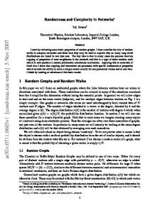
Fig. 1.
A 9-input Clos permutation network.
tradeoff in this case is hardware cost; Batcher sorters use @(nlog2n) switches whereas Clos networks can be minimized to have O ( nlog n) switches. In all three networks, the fact that the information complexity of routing the first stage is a constant and also that these networks have a recursive structure explain why, they are very easy to route. In contrast, the main result of this paper shows that the information complexity of routing the first stage (as well as the second and third stages) of a Clos network is about as large as the number of inputs to the network, and this explains why these networks cannot be routed as they are traversed. The remainder of the paper is organized as follows. Section 11 states preliminary facts needed in subsequent sections. Section III introduces the notions of multiloops and balanced multiloops, and Section IV uses these to obtain the claimed information complexity lower bound. Section V uses this lower bound to determine the time complexities of various routing schemes for Clos networks. In Section VI extant routing algorithms are compared to the bounds. The paper is concluded in Section VII.
II. PRELIMINARY FACTS A three-stage Clos network will be defined in terms of two parameters, m and k where m is the number of inputs to each of the switches in the outer stages, and k is the number of inputs to each of the switches in the center stage [8], [SI. The total number of inputs (outputs) to the network is mk and will be denoted by n. Note that k is also the number of switches in each of the outer stages while m is also the number of switches in the center stage. The interconnections between consecutive stages are such that there exists exactly one link between every center- and outer-stage switch. For example, a Clos network appears in Fig. 1 for n = 9, and m = k = 3. Input and output terminals to the network will be labeled by pairs ( i , j ) ; 0 5 i 5 IC - 1, 0 5 j 5 m 1 where (i, j ) denotes the j t h input or output (depending on context) of switch i. A permutation A to be realized by the network will be specified in the form of [(i, j ) , ~ ( ij ), ] , 0 5 i 5 k - 1, 0 5 j 5 m - 1 where ~ ( ij ), is the output to which input (i, j ) is mapped. When we do not wish to emphasize to which switches inputs or outputs belong, we will denote them by integers 0, 1,. . ,n - 1 and express A as [i, a ( i ) ] , 0 5 i 5 n - 1. Permutations for the input, center, and output stages will be denoted by A I , A M , TO, respectively. Our model of routing a Clos network, to be called a muter, will be a black box that receives a permutation A in the form of a set of assignments and returns a set of settings for the switches in the network so as to realize A. These settings, for each stage of the network, may be viewed as a permutation A., s E {I,M, 0).For a fixed z, a,, and s, A.(z, y) specifies the image of input y of switch z in stage s, i.e., the output of switch z in stage s to which its input a, is mapped.
-
.
Authorized licensed use limited to: University of Maryland College Park. Downloaded on January 30, 2009 at 14:20 from IEEE Xplore. Restrictions apply.
IEEE TRANSACTIONS ON INFORMATION THEORY, VOL. 40, NO. 1, JANUARY 19%
280
In determining switch settings, we will be interested only in the minimum number of assignments that the router must use, i.e., the information complexity of setting switches, rather than the actual computation that the router engages in to determine the settings. Once such an information lower bound is obtained then the structure of the router can be brought to bear on that bound to determine a lower bound on its routing time. The information bound on routing a three-stage Clos network will be derived by finding dependencies between assignments in x and settings in permutations x g . Dejinition I: ”bo permutations R I and x z are said to differ on a set of inputs if their assignments on those inputs are different. For example, xi = [0, 41, 11, 31, 12, 11, [3, 21, 14, 51, 15, 01 and =z = [0, 41, [l, 31, [2, 11, [3, 21, [4, 01, [5, 51 differ on inputs 4 and 5 . 0 Definition 2: Let x be a permutation to be realized by a Clos network and A be a subset of inputs of stage s E {I,M , 0 ) .Define V A ( Xs) , to be the set of all mappings of the subset of inputs A of stage s which do not prevent the Clos network from realizing x . 0 The set V A ( Xs) , will be used to define the dependencies between the assignments in x and settings in x s . DeJinition 3: Let A be a set of assignments and let A and s be defined as above. The mappings of inputs in A are said to be dependent upon A (briefly, A depends on A) if there exist two permutations x l and 7r2 which differ only in inputs which appear in the assignments that belong to A and such that VA(TI, s) n vA(T2, 8) = 40 Because V A ( T s) ~ , n V A ( X Zs), = the router must provide different mappings for the inputs in A under x1 and xz if the network is to be set up properly. To distinguish x l and xz the router must examine the assignments in A. That is, if A depends upon A, a router which computes A must base its computation on the part of the permutation specified by A. Although dependencies are defined above for a set of assignments, it will be useful to define them for an individual assignment. This cannot be done directly using the above definition because the permutations R I and x z cannot be found when A contains exactly one element, since if two permutations differ they must differ in at least two places. Despite this fact, the dependency of a switch setting on a subset of assignments can be inferred indirectly as stated in the following. Proposition I: If the mappings for a set of inputs A of a set of switches depend upon a set of assignments A, then they depend on at least one of the assignments in A. The set A may depend on A without having to depend on all the assignments in A. That is, we may have two permutations x l and xz which differ only on assignments in A and for which the mappings of the inputs in A may be disjoint, but no two such permutations may exist for some subset of A. The following results establish that, under certain conditions, we may determine the number of “element-wise” dependencies from “subset-wise” dependencies. Lemma I: If the mappings for a set of inputs A of a set of switches depend upon all subsets of assignments of cardinality T of a set of assignments A then they depend upon at least IAI - T +1 assignments. Proof: The largest set of assignments which A could not depend on, consistent with the Lemma, is one with cardinality r - 1, so A depends on at least IAl - r 1 assignments. 0 Lemma 2: Given an input 6 of a switch and z disjoint sets of assignments Ao, A I , . . ,A,-1, if the mapping of 6 depends upon A, U A, for all 0 5 i < j < H then it depends upon either all, or all but one of the A,. Proof: Suppose the mapping of 6 does not depend on one of the sets, say Ao. Then it must depend on A,; 1 5 i 5 z - 1 since it depends on AOU A, for all i ; 1 5 i 5 z - 1. 0
o
+
.
These facts, combined with the results of Section 111, will be used in Section N to find the minimum number of assignments necessary to determine the stage settings for a three-stage Clos network for some permutations. Once the dependencies are determined the lower bound on the time it takes to route a 3-stage Clos network immediately follows.
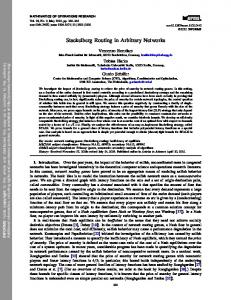
m. PERMUTATIONS AS MULTIGRAPHS AND MULXIL00P.S To find the dependencies, permutations with special properties will be described. These permutations will be represented as bipartite multigraphs. Let z k = (0, 1,. . . ,k - 1). w e shall write (I,M , 0 ) to denote a bipartite multigraph with two disjoint sets of vertices, I = z k , and o = z k , and a mu~tiset~ of edges M c (I x O)m connecting the two sets of vertices where (I x O)m is a multiset containing I x 0 m times. The elements in I will be referred to as leji vertices, and represent the input-stage switches while the elements in 0 will be referred to as right vertices and represent the outputstage switches. An edge between left vertex i and right vertex j will be denoted by [i, j].For each permutation x , the set M contains r edges [i, j ] iff x ( i , z) = ( j , y) for exactly r distinct pairs of integers (5, y) where 2 (y) is an input (output) of switch i ( j ) in the input (output) stage. Thus, when a left vertex i is connected to a right vertex j by r edges the connection represented has exactly T inputs which are mapped from input-stage switch i to output-stage switch j under the corresponding permutation. Each (2, y) pair specifies an input z of input stage switch i which is connected to output y of output stage switch j . Furthermore, it can be shown that for any given m and k , the bipartite multigraph representation of each permutation for an n-input Clos network is unique, while many permutations can have the same bipartite multigraph representation. For any given permutation, the permutations for the center stage of a Clos network that result in the realization of that permutation can be identified by m-edge-colorings of its corresponding bipartite multigraph. A bipartite multigraph is said to be m-edge-colored if its edges are colored such that no two edges of the same color are incident on the same vertex and exactly m colors are used. It is well known that m colors suffice to edge-color a bipartite multigraph of degree m [ l l ] . Furthermore, it is well known that there is a correspondence between an m-edge-coloring of a bipartite multigraph representing a permutation x for a Clos network, and the center-stage permutation x , ~ (See . [21], [24] for an early application and [7] for a thorough treatment.) An example is depicted in Fig. 2 for a Clos network with m = 2, k = 4. Edges between left and right vertices that are labeled with color 0 are assigned to the upper switch in the center stage, and those colored with 1 are assigned to the lower switch. In order to exhibit the dependencies of the permutations of the center-stage switches on the permutations to be realized by a Clos network we need to consider m-edge-colorings of the bipartite multigraph representations of certain permutations. These permutations will be identified by some particular subgraphs which we shall refer to as balanced multiloops. We will show that these subgraphs can be edge-colored only two different ways. This fact will then later be used in Section IV in the construction of dependencies between the inputs and outputs of a router for three-stage Clos networks. Definition 4: A bipartite multigraph, (I,M , 0),is a multiloop of size 1 if III = E = 10)and, if, when multiple edges between pairs of vertices are taken as one, the graph consists of a single loop. 0 3A multiset is a set that may contain multiple copies of a single element, for example, { a , a , b, c } .
Authorized licensed use limited to: University of Maryland College Park. Downloaded on January 30, 2009 at 14:20 from IEEE Xplore. Restrictions apply.
IEEE TRANSACTIONS ON INFORMATION THEORY, VOL. 40, NO. 1, JANUARY 1994
281
Fig. 4.
Examples of unmixed and mixed colorings of a multiloop.
of balanced multiloops, however, the number of such maps can be reduced to two cases as argued below. Definition 7: Divide the set of m colors assigned to the edges of a multiloop into two sets of colors; shades of blue, SB = {bo, b l , . . ,bm/z-l}, and shades of red, SR = {TO, T I , . . . ,~ , p - ~ An } . m edge-coloring of a multiloop is said to be unmixed if the edges between any two vertices receive colors from SR or from SB but not both. Otherwise, it is called mixed. 0 Examples of unmixed and mixed edge-colorings of a multiloop are shown in Fig. 4. It can be seen that in the unmixed coloring, the edges (whenever they exist) between a left vertex and right vertex are colored either with shades of red, i.e., TO and T I , or shades of blue, i.e., bo, and b l . On the other hand, the mixed coloring does not follow this convention as can be seen in Fig. 4@). Lemma 3: A balanced multiloop can have exactly two unmixed m edge-colorings when edges between a pair of vertices are not considered distinct. 0
.
Fig. 2.
A bicolored bipartite multigraph and corresponding Clos network.
Iv. CONSTRUCTION
Fig. 3.
Examples of multiloops shown in heavy lines form = 2 and IC = 4.
Dejnition 5: A bipartite multigraph, (I,M, 0),contains a multiloop of size E if there exists IL I, OL 0, and M L = {[z, y] I z E I L , y E O L , [z, y] E M} such that I I L ~ = I = 10~1 and the graph (IL,M L , O L )is a multiloop. 0 Definition 6: A multiloop ( I L ,M L , O L ) is called balanced if it is regular with degree m and for all pairs [ i , j ] , i E IL and j E O L , ML contains either no edges or exactly m12 edges between vertex i and vertex j . That is to say, every pair of vertices which are connected are connected by m12 edges. 0 Examples of ordinary (i.e., not balanced) and balanced multiloops are given in Fig. 3 for a Clos network with m = k = 4 where the heavy lines represent the edges in the loops. In both loops, I L = (1, 2, 3}, OL = (0, 1, 2). When a bipartite multigraph is m-edge-colored, it induces an medge-coloring on any of its multiloops. For example, when the graphs in Fig. 3 are colored, each of the multiloops ends up having an edge-coloring with four colors. In general, a multiloop of a bipartite multigraph of degree m can be edge-colored by using m colors, and no less since the degree of each vertex in any such loop is m. There exists a bijective mapping between these m colors and the m centerstage switches of the corresponding Clos network in that all the edges in a multiloop with the same color are mapped to the same centerstage switches. Obviously, this mapping is not unique, as the colors can be mapped to the switches in any one of m! ways. In the case
e
e
OF
DEPENDENCIES
We proceed by constructing two permutations based on two balanced multiloops. Dehition 8: Let there be two sets of four vertices { M O , 211, W ,w 3 } I, and { V O , 0 1 , V Z , 03) 0 where I and 0 are two k-sets of vertices. We construct two multiloops (IioOp, Mioop,OioOp)and (IioOp, M:oop, OioOp)such that Iloop
= {MO, U l ,
u2, u 3 }
cI,
where [ U , 0Iml2 denotes “edge [ U , 01 repeated m/2 times.” A permutation whose bipartite multigraph (I,M, 0) has (hoop,MiooprOloop) as a subgraph is denoted nloop. Similarly, a permutation whose bipartite multigraph (I,M, 0) has (Iioop, hf~oop, oioop)as a subgraph is denoted n{oop. The subgraphs of these permutations will be referred to as loops. Obviously this extension is not unique, and many permutations can be constructed this way. The two permutations are similar in two respects. Their bipartite multigraph representations both have
Authorized licensed use limited to: University of Maryland College Park. Downloaded on January 30, 2009 at 14:20 from IEEE Xplore. Restrictions apply.
IEEE TRANSACTIONS ON INFORMATION THEORY, VOL. 40,NO. 1. JANUARY 1994
282
+
the same left and right vertices and most edges in common: The only difference is that MloOpcontains edges [ U I ,vl]m/2 and [us,voIm/' which Mioopdoes not and contains edges [ U Z , v l ] m / z and [ U I ,v ~ ] ~ /which ' Mloop does not. Finally, the two permutations contain balanced multiloops of size 4. By Lemma 3 each of these loops can be edge-colored using shades of two colors in exactly two ways. Table I lists the correct mappings for inputs uo and uz of a center-stage switch c under AM that can route ~l~~~ and A ; ~ , ~ .Here, T indicates that the edges between vertices uo and W O are colored with colors from SR and b indicates that these same edges are colored with colors from SB. AM(C, U O ) denotes the output of switch c to which A M maps input uo of that switch. AM(C, U Z ) is similarly defined. We also emphasize that output c of input stage switch uz connects to input U = of center-stage switch c; similarly, output wy of center-stage switch c connects to input c of output-stage switch vy for all e, y E z k . (see Table I.) Suppose A = {(c, UO), (c, UZ)}. Then the possible mappings ~ V~ A ~ ( A I ~A M~)~ ,= for the inputs in A under ~l~~~ and A [ are {[(c,vo), (c, vz)], [(c,vi), (c, w)]}, and AM) = { [ ( c , WO), (c, v3)1, [(c, vi), ( C Y vz)]). Let U,, = {(uz,j) I j E Z,} be the set of inputs of input-stage switch ut. Since VA( ~ i A M~ ) n ~ VA ~ ( , T [ ~A M ~ ) ~=, 4, and AI^^^ and differ only on assignments in sets U,, and U,,,by Definition 3, we conclude that mappings for the inputs in A must depend on assignments in U,,U U,,. Theorem I: For all distinct U O ,U I ,U Z ,u3 E Zk and c E z,, mappings for inputs (c, UO), (c,U Z ) of the center-stage switch c depend upon assignments for inputs in U",U UuQ, Now, consider a family of loop permutations ~l~~~ and H { in~ which uo and uz are the same in each permutation, but where u1 and u3 can take on arbitrary values. Regardless of how u1 and u3 are chosen, VA AI^^^, AM) n VA(A { ~ A~M ~) = , 4, whence Theorem2: For d l distinct UO, uz E z k and c E z,, the mappings for inputs (c,UO), (c, U Z ) depend upon the assignments in each of at least k - 3 of U,,i E Zk\{UO, UZ}. Proof: For U O ,uz E z k , choose u1, 113 E &\{uo, UZ}. Construct moOp and T : , , ~ from these values. By Lemma 2 and Theorem 1 the k - 3 dependencies are obtained. 0 Theorem 3: For d l distinct U O ,u2 E z k and c E mappings for inputs (c, UO),(c, U Z )in A M depend upon at least ( k - 3 ) ( m / 2 + 1) assignments. Proof: If A = {(c, UO), (c, UZ)} depends on assignments on U,, then it must depend on assignments on every subset of mi2 elements in U , since, for every m / 2 elements chosen out of Ut, we can define two permutations (by appropriate choice of SR and SB) which conform to the structure of ~l~~~ and A { ~ , ~ Therefore, . by Lemma 1, there are at most m / 2 - 1 assignments A does not depend upon. Combining this fact with'Theorem 2 we conclude that there are (k - 3 ) ( m / 2 1) assignments which A depends upon. 0 Note that A contains two elements. Since it cannot be determined which of the two elements depend upon which assignments, the assignments must be divided evenly, to have a correct (worst case) lower bound on the number of dependencies. Thus, a setting in A M
(0, i ) (1, 0 ) (0, i ) 4 x 7 Y) = (0, 21, (0, i ) (1,O) 7r'(O, i) = (0, i) (0, w) (0, i )
~ ( 0i ,) =
v ~ ( ~ i ~ ~ ~ ,
z,,
+
+
depends upon at least ( k - 3 ) ( m / 2 1 ) / 2 = ( k - 3 ) ( m 2 ) / 4 assignments. Although the dependencies were derived for the settings of the center stage switches, they apply to all stages. That is, permutations AI^^^ and A { induce ~ ~ disjoint ~ settings in input-stage switches uo and uz and output-stage switches vz and w3, so that the same dependencies apply. The result just derived does not hold for Clos networks with k 5 3. This is because we cannot form balanced loops when k 5 3 . To find dependencies in these networks consider a router, this time, for the input-stage switches, and consider the mapping of input (e,y), i.e., input y of switch c in the input stage. This result will be derived for a Clos network in which switch 0 in the input stage is fixed in the identity state. It has been shown that such networks can realize all permutation connections [31I. Theor.": The mapping of input (e,y) depends upon at least m - 1 assignments. Pro03 Construct two permutations A and A' in the following way:
Af(Z,
{
I
05i i =z z