DREAM: A Practical Product Line Engineering using Model Driven Architecture* Soo Dong Kim, Hyun Gi Min, Jin Sun Her, Soo Ho Chang Department of Computer Science Soongsil University, Seoul, Korea
[email protected], {hgmin, jsher, shchang}@otlab.ssu.ac.kr Abstract Both product line engineering (PLE) and model driven architecture (MDA) are emerging as effective paradigms for building a family of applications in cost effective way. PLE supports this by reusing common assets and MDA supports this by generating applications on diverse platforms through model transformation. However, both technologies have shortcomings to be a comprehensive methodology. The instructions and artifacts of PLE processes are not yet precisely defined. Especially, instructions for detailed design considering implementation platforms are not yet provided. Careful observations on PLE and MDA reveal that they complement each other by overcoming their limitations. We find a possibility of seamless integration, resulting in a comprehensive commerciallevel methodology. In this paper, we propose a practical product line methodology, DREAM, which adopts key activities of PLE and model transformation feature of MDA. By applying the proposed methodology, it becomes possible to efficiently and semi-automatically develop a large number of applications that vary on behavior and implementation platform.
1.
Motivation
Both product line engineering (PLE) and model driven architecture (MDA) are emerging as effective paradigms for building a family of applications in cost effective way. PLE supports this by reusing common assets derived through domain engineering [1,2,3], and MDA supports this by generating applications on diverse platforms through model transformation[4,5]. However, both technologies have shortcomings to be a comprehensive methodology. Instructions and artifact templates of PLE are not yet precisely defined, especially the application engineering process of PLE. *
Moreover, the instructions for detailed design considering implementation platforms are not yet provided. Hence, the final deliverable of application engineering in PLE still remains as a conceptual model. On other hand, MDA does not include process and instructions to model reusable assets that can be shared by multiple organizations in a domain. From our careful and thorough observations on PLE and MDA, we conclude that they complement each other by overcoming their limitations, and found a possibility of seamless integration, resulting in a comprehensive commercial-level methodology. In this paper, we propose a practical product line methodology DRamatically Effective Application development Methodology (DREAM) that adopts the key activities of PLE and model transformation feature of MDA. By applying the proposed methodology, it becomes possible to efficiently and semi-automatically develop a large number of applications that vary on behavior and implementation platform. Hence, the practical applicability of PLE and the application development productivity are greatly increased. We first present a brief survey of related works in section 2, the overall strategy of integrating PLE with MDA is given in section 3, and the characteristics of various artifacts are discussed in section 4. Section 5 presents the overall DREAM process, followed by specification of each phase. The traceability among various artifacts is discussed in section 6 as a purpose of assessing the proposed methodology.
2.
Related Works
Muthig’s work introduces a concept of integrating MDA and PLE in software engineering [6]. Initially, a meta-model of core assets is created, consisting of generic assets and a decision model. By specifying a product line at a meta-level, utilizing the model
This work was supported by Korea Research Foundation Grant. (KRF-2004-005-D00172)
Proceedings of the Third International Conference on Information Technology and Applications (ICITA’05) 0-7695-2316-1/05 $20.00 © 2005 IEEE
transformation of MDA becomes feasible. Beyond this concept of integrating MDA and PLE, this work does not provide a systematic process with applicable work instructions and artifact representations. Moreover, it is not clear how to represent the core asset in PIM and PSM and how to map the models.
3.
Strategy to Integrate MDA into PLE Process
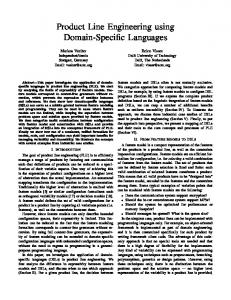
We first define a PLE process and terms which reflect the representative recent works on PLE, as in figure 1. In the figure, PLE process consists of two distinct sub-processes; framework engineering and application engineering. Each sub-process consists of up to four phases. The framework implementation phase is needed to realize the framework design for a particular platform, but this phase is not explicitly specified in most representative PLE processes. Similarly, application specific construction and integration & deployment phases are needed to implement application specific functionality. The figure also shows artifacts and shortcomings of PLE process as a comprehensive commercial methodology. Artifacts are listed on the left-hand side of the phases, and the shortcomings are listed on the right-hand side.
Application Engineering
Framework Engineering
Artifacts C&V
PL Scope
Now, we discuss strategies of integrating PLE and MDA by illustrating how MDA construct can complement the PLE shortcomings. Then, the section 4 presents the overall model-driven PLE process and work instructions in more details. First, PLE does not provide templates or standards for representing framework design. The platform independent model (PIM), platform specific model (PSM) and meta object facility (MOF) of MDA can be used to represent the generic architecture, components, and their interactions of framework design. Current PLE processes do not provide implementation details of frameworks. To implement frameworks, platform specific constructs and mechanisms should be considered into the detailed design. MDA can complement this with mechanism to transform PIM to PSM which is a detailed design model for a particular platform such as Java, EJB, and .NET. Current PLE application engineering includes framework instantiation phase, but concrete instructions to instantiate the given framework are not provided. The model transformation mechanism of MDA can be used to map generic framework to instantiated framework if decision models and application specific decisions including variants are expressed in MOF.
Phases
Shortcomings
Domain DomainAnalysis Analysis Scoping Scoping Product Product Line Line
Framework Design Spec. & Decision Model
Framework Framework Modeling Modeling
Implemented Framework & Attached Instruction
Framework Implementation
Application Analysis Model
Application Application Req. Req. Analysis Analysis
Instantiated Framework
Framework Framework Instantiation Instantiation
Application Specific Code which is not covered by framework
Application Specific Construction
Completed System (including framework and application code)
Integration & Deployment
Lack of Concrete Templates or Standards to represent the framework design No concrete instruction to implement frameworks
No concrete instruction to instantiate frameworks
No concrete instruction to generate application code from framework
Fig. 1. Phases, Artifacts and Shortcomings of PLE Process shown in the figure 1. To produce an operational Current PLE processes do not explicitly specify the software system, the framework and application application specific construction and integration as
Proceedings of the Third International Conference on Information Technology and Applications (ICITA’05) 0-7695-2316-1/05 $20.00 © 2005 IEEE
specific implementation should be integrated into a single executable system. MDA transformation mechanism can be used to map framework PSM and application specific PSM into executable code. In summary, a PLE process augmented with the presentations and mappings of MDA enables PLEbased software development.
4.
Characteristics of DREAM Artifacts
Application of DREAM process produces various artifacts with different characteristics. In PLE and MDA, new artifacts are produced by transforming, instantiating or integrating existing artifacts. Hence, it is essential to understand similarity and difference among various artifacts. Table 1 lists characteristics of artifacts in terms of Scope, Genericity, and Form. Scope describes what portion of a whole system is covered by the artifact. For example, generic framework covers only the core part of the entire system. Genericity indicates whether the artifact is for various members in the domain or for a specific member. For example, generic framework is for reuse by members, but instantiated framework is
Framework Engineering
Phases of DREAM
Artifacts Product Line Scope Generic Framework Instantiated Framework Application Specific Model Integrated P.I. Model Integrated P.S. Model Integrated Code
Artifacts in PLE
Scope
Genericity
Form
Core Part
Generic
Description
Core Part
Generic
P.I. Model
Core Part
Specific
P.I. Model
Specific Part
Specific
P.I. Model
Application
Specific
P.I. Model
Application
Specific
P.S. Model
Application
Specific
Code
Representation in MDA
Domain Domain Analysis Analysis (by (byC&V C&VAnalysis) Analysis)
Product Product Line Line Scoping Scoping (by (byDeveloping Developing Business Business Case) Case)
Framework Framework Modeling Modeling (by (byDesigning Designing Framework) Framework)
Application Application Req. Req. Analysis Analysis (by (byConventional Conventional OOA) OOA)
Application Engineering
for a specific product. Form is used to denote the levels of abstraction in terms of life-cycle; P.I. model is more or less a preliminary design artifact, P.S. model is a detailed design artifact considering implementation platform, and code is an implemented source or binary program. Table 1. DREAM Artifacts and their Characteristics (P.I. stands for platform independent, and P.S. stands for platform specific.)
Application Application Specific Specific Design Design (by (byExpressing Expressing OOD OOD as as PIM) PIM)
Framework Framework Instantiation Instantiation (by (bySetting Setting Variants) Variants)
Model Model Integration Integration (by (byIntegrating Integrating two two PIMs) PIMs)
Application Application Detailed Detailed Design Design (by (by PIM PIM to to PSM PSM Mapping) Mapping)
Application Application Implementation Implementation (by (byPSM PSMto to Code Code Mapping) Mapping)
C&V Specification
Product Line Scope
Generic Framework
(Generic) PIM
Application Analysis Model
Application Specific Design
(Application Specific) PIM
Instantiated Framework
(Instantiated) PIM
Integrated Appl. Appl. Model
(Application) PIM
Detailed Design Model
(Application) PSM
Application Code
Application Code
Fig. 2. Process of Model-Driven PLE
Proceedings of the Third International Conference on Information Technology and Applications (ICITA’05) 0-7695-2316-1/05 $20.00 © 2005 IEEE
5.
Process and Instructions
In this section, we present the overall process and instructions to carry out each phase. We also define templates of various artifacts. Figure 2 shows the 9 phases of DREAM, their associated artifacts in PLE and representations in MDA.
5.1. Domain Analysis Instruction: Domain analysis is to understand features of several organizations in a single domain and to analyze their commonality and variability (C&V). A feature can be functional such as business logic or extra-functional such as quality attributes. Hence, this phase delivers a specification of common features and variability among organizations. There are several approaches to domain analysis. For the instruction of this phase, we refer to some of effective techniques such as [7]. Representation: Any reasonable representation scheme may be used to specify the result of domain analysis, but the specification should define the set of common features. Variability plays a key role in PLE and variable feature is specified with its variation points and possible variants as shown in table 2. Table 2. Variability Range Table Variable Type of Set of Features Variation Variants CF1 Logic {V1.1, V1.2} CF3 Workflow {V3.1, V3.2} ... CFm Logic {}
Open/ Default Description Closed Closed V1.1 Open V3.2 Open
None
The first column lists the variable features, CFi, the second column specifies the type of variation, and the third column Set of Variants lists all the variants identified; V3.2 is the 2nd variant of feature numbered as CF3. The next column, Open or Closed, indicates whether the list of variants identified is complete, i.e. closed, or expandable in the future, i.e. open. Depending on this openness, different implementation techniques can be adopted. The next column, Default, specifies a default variant among the list of variants.
5.2.
Product Line Scoping
Instruction: Not all the common features need to be realized in reusable frameworks. Product line scoping is to determine the scope of a product line. By analyzing the specification of C&V in the variability range table, this phase determines a set of potential products that can be constructed from a product line based on economic analysis and any relevant selection criteria. One may use the business case analysis
technique [8] to evaluate the potential return on investment. Although the criteria used for the scoping should be developed for each domain, some of general criteria are the number of potential products, the scope of commonality, the range of variability, and the genericity of quality attributes supported. Representation: The scope of a product line is essentially a subset of a domain model. Hence, the representation scheme used in the previous phase can be used. Optionally, the business case analysis used in the scoping may be described.
5.3.
Framework Modeling
Instruction: There is no strong consensus on the term that describes infrastructure of product line from which various products are instantiated. It may be called framework, core asset, product line infrastructure or common architecture, but we adopt the term framework. The framework modeling phase is to realize the C&V into a framework. It is generally agreed that a framework includes an architecture generic to product line members, software components, and their relationships and constraints. The first step of framework modeling is to design the generic architecture by considering the potential applications of the product line. Generic architecture should capture all the essential and common structural and behavioral elements of potential applications. Then, appropriate architecture views and styles are selected and tailored [9]. The second step is to locate components that all together can realize the required features. COTS components can initially be considered, and then in-house components needed are identified. For partially matching components, one may consider connectors that can mediate the component behavior [10]. We now develop a decision model which describes variation points, variant and mechanism to tailor the framework. This mechanism will be used to tailor the framework for a specific application in a later phase framework instantiation phase. If a variation point has a Closed scope, it is tailored by using Select( ) method. This method will take variants required by each application and store them persistently. If a variation point has a completely Open scope, then it is tailored by using PlugIn( ) method. This method will take a reference to an external function, object or component, and invoke the method provided by the plugged in entity. If a variation point has a partially Open scope and some variants are known, then we use both Select( ) method and PlugIn( ) method.
Proceedings of the Third International Conference on Information Technology and Applications (ICITA’05) 0-7695-2316-1/05 $20.00 © 2005 IEEE
Representation: The generic framework is the most essential element of a product line, and we represent the framework as a PIM to utilize the model transformation scheme of MDA. The generic PIM consists of object model, interaction model and optionally other UML diagrams. Hence, the generic PIM which is the representation of framework should conform to the UML and MOF specifications, and we do not repeat explaining them here. To automate the framework instantiation in a later phase, the decision model should also be represented in a well structured form so that it can be effectively interpreted by framework instantiation tool. We suggest two methods of representing the decision model; using the stereotypes and tagged values of UML, or adopting the XML or XMI representation.
5.4.
Application Requirement Analysis
Instruction: A framework typically provides a large set of features common to a family of applications, but not all the features of an application are provided by the framework, as in figure 5. That is, an application may have application specific features. The application requirement modeling phase is to analyze the requirement of an application and to identify the application specific features. Conventional OO analysis technique can be used for this phase. In consequent phases, the application specific features must be designed and integrated with the framework into a complete product. Application Specific Features
Framework Framework
integrated later. Conventional OO design technique can be used for this phase. An important design criterion is that the framework should be designed so that it can be effectively integrated with framework model in a later phase, model integration. Hence, the framework architecture, interface and constraints must be considered during this design phase. Representation: The application specific design is represented as a PIM model to utilize automatic model integration. Application specific PIM is identical to the generic PIM except the content of PIM is only relevant to a specific application.
5.6.
Framework Instantiation
Instruction: This phase is to instantiate the framework for an application. Using the decision model of the framework, variants specific to the application are set into variation points, resulting in an instantiated framework. As shown in figure 6, MDA transformation mechanism can be used to map generic framework to instantiated framework if decision models and application specific decisions including variants are expressed in MOF. To automate the instantiation process, mapping rules that map elements of generic framework to elements of instantiated framework are required, as in the figure. Decision Model
Generic Generic Framework Framework
Representation: Application analysis model can be represented in any form as long as the semantics of the model is well preserved. It is only an analysis model and so it is not represented as a PIM yet. Once the analysis model is refined as a design model in the next phase, then it is represented as a PIM. Hence, a conventional UML representation can be used to specify application analysis model.
5.5.
Application Specific Design
Instruction: This phase is to realize application analysis model at platform independent design level. Application specific components and interfaces are designed so that the framework can be effectively
Instantiate Framework by Transformation
Instantiated Instantiated Framework Framework
Mapping Rules for Instantiation
Application Application
Fig. 3. Application Specific Features
Application Specific Decision
Fig. 4. Instantiation by MDA Transformation
Representation: The representation of instantiated framework will still be same as the generic framework, i.e. generic PIM. Only the variable part of generic PIM is tailored for given variants of a specific application.
5.7.
Model Integration
Instruction: In DREAM like other PLE processes, the framework model and the application specific model should be integrated into a complete application. Implementing two models and integrating those two implementations would be less feasible than integrating two models first into a single model and implementing a single model. This phase is to integrate these two models and to produce a single coherent
Proceedings of the Third International Conference on Information Technology and Applications (ICITA’05) 0-7695-2316-1/05 $20.00 © 2005 IEEE
design model, so that, in later phases, it can be effectively implemented for a specific platform. While MDD focuses on transforming abstract model into more concrete model, model integration is not directly supported in MDD. Hence, it may not be done automatically by tools, but integrated by hand. Representation: The representation of the integrated model will still be a conventional PIM. The scope of the integrated PIM is the entire application so that it can be transformed into a PSM in the next phase.
instructions utilizing UML and representation scheme utilizing PIM and PSM of MDA. We focused on the seamless transformation between artifacts, and the traceability of artifacts was provided. By applying the proposed methodology, it becomes possible to efficiently and semi-automatically develop a large number of applications that vary on behavior and implementation platform.
References 5.8.
Application Detailed Design
Instruction: This phase corresponds to the detailed design phase of conventional life-cycle. That is, the integrated application design model is refined by considering platform specific characteristics such as programming language, middleware and component platform. A key difficulty in this phase is to define a set of mapping rules that takes integrated model into detailed design model. Candidate techniques can be marking, action semantics, UML profile and metamodel mapping. If the detailed design can be expressed as a toolrecognizable form, then the process of mapping PIM to PSM can be automated. Representation: The representation of detailed design model is the conventional PSM which includes platform specific decisions.
5.9.
Application Implementation
Instruction: This phase is to take the application PSM and to produce executable application code and other associated implementations such as database. This can be done by using the PSM to Code mapping facility of MDA. To automate this model transformation, an appropriate UML profile can be used to specify various instructions on how to map PSM elements to code elements. Representation: This phase delivers application code and associated implementations. The representation of deliverables will be the final output for a selected platform.
6.
Clements, P., et al., Software Product Lines: Practices and Patterns, Addison-Wesley, 2002. [2] Atkinson, C., et al., Component-based Product Line Engineering with UML, Addison Wesley, 2001. [3] Bayer, J., et al, “PuLSE: A Methodology to Develop Software Product Lines,” Proceedings of the Symposium on Software Reusability (SSR’99), Los Angeles, May 1999. [4] OMG, Model Driven Architecture (MDA) Specification, 2001. [5] OMG, MDA Guide, Version 1.0.1, 2003. [6] Muthig, D. and Atkinson, C., “Model-Driven Product Line Architectures,” LNCS 2379, Proceedings of the 2ND Software Product Line Conference, 2002. [7] Choi, S., et al., “A Systematic Methodology for Developing Component Frameworks,” LNCS 2984, Proceedings of the 7th Fundamental Approaches to Software Engineering Conference, 2004. [8] Williams, J., “The Business Case for Components,” Component-Based Software Engineering: Putting the Pieces Together, Heineman G. and Council, W., ed., Addison-Wesley, 2001. [9] Clements, P., et al., Documenting Software Architectures: Views and Beyond, Addison-Wesley, 2003. [10] Min, H. and Kim, S., “Using Smart Connectors to Resolve Partial Matching Problems in COTS Component Acquisition,” LNCS 3054, Proceedings of 7th Component-Based Software Engineering Conference, 2004. [1]
Concluding Remarks
Both PLE and MDA are emerging as effective paradigm for building a family of applications in cost effective way. However, both technologies have shortcomings to be a comprehensive methodology for developing applications. In this paper, we proposed a practical product line methodology, DREAM, that adopts the key activities of PLE and model transformation feature of MDA. The process consists of 9 phases, and each phase was specified with work
Proceedings of the Third International Conference on Information Technology and Applications (ICITA’05) 0-7695-2316-1/05 $20.00 © 2005 IEEE