A Practical, Real-Time Speech-Driven Home Automation Front-end Theodoros Giannakopoulos, Nicolas – Alexander Tatlas, Todor Ganchev and Ilyas Potamitis
Abstract — This work presents an integrated system that uses speech as a natural input modality to provide userfriendly access to information and entertainment devices installed in a real home environment. The practical limitations introduced by the on-line nature of the application as well as the implementation challenges and solutions are analyzed. The focus of the present study is on the implementation on the front-end signal pre-processing block that consist of an array of 8 microphones connected to a multi-channel soundcard and a tandem of workstations performing all signal pre-processing tasks, such as, acquisition, filtering, and beamforming. Evaluation of the beamformer’s performance in realistic home environment with controllable noise sources is provided. Furthermore, speech and speaker recognition results using the front-end that was deployed are presented.1 Index Terms — Acoustic beams, acoustic signal processing, speech processing, speech recognition.
I. INTRODUCTION The ever-increasing complexity of home appliances and services, combined with the difficulties encountered by a great portion of the population to handle complex equipment including the inability of elderly and disabled people to use it, renders the creation of intelligent, intuitive and flexible interfaces that facilitate the human-machine interaction, an endeavor of great importance. As humans predominantly communicate via spoken language, a natural interface should allow the user to interact with the home environment directly using his/her voice requesting an agent to perform some action on behalf of the user. The general problem addressed in this work is that of handsfree speech recognition in a reverberant room where users walk while engaged in conversation in the presence of different types of house-specific noise sources (e.g., TV/radio broadcast, interfering speakers, ventilator/air-condition noise, 1
Manuscript received June 21, 2005. T. Giannakopoulos is with the Informatics and Telecommunications Dept., University of Athens, 15784 Greece (phone: +30 210 7275340; fax: +30 2107275191; e-mail:
[email protected]). N.-A. Tatlas is with the Electrical and Computer Engineering Dept., University of Patras, 26500 Greece (phone: +30 2610 996838; fax: +30 2610 991855; e-mail:
[email protected]). T. Ganchev is with the Electrical and Computer Engineering Dept., University of Patras, 26500 Greece (phone: +30 2610 997336; fax: +30 2610 997336; e-mail:
[email protected]). I. Potamitis is with the Technological Educational Institute of Crete, Department of Music Technology and Acoustics, Daskalaki-Perivolia, 74100, Rethymno, Crete. E-mail:
[email protected] Tel.: +30 2831 023747 Fax: +30 2831 058323).
etc.). The subsequent exposition focuses on implementation details and practical considerations concerning the integration of diverse technologies (such as Direction of Arrival (DOA) estimation, beamforming, and automatic speech and speaker recognition) into a real-time system. The design of our system was carried out under the following assumptions: (a) it is probable that several potential speakers share the same room; (b) the speakers can be moving while talking; (c) the main sources of interference are nondesired speakers and music. This kind of non-stationary interference shares the same statistical characteristics with the signal of the desired user. The challenges faced by the front-end of the system are related to the acoustic adversity of home environments using distant microphones. The system should be able to receive commands and interact with the user while moving, in the presence of competing speaker and music interference as well as stationary noises originating in home appliances. From the users’ point of view, microphone arrays are preferable sound acquiring device since they are placed on the wall and/or ceiling, and thus are less intrusive, not causing any discomfort as opposed to wearing headsets, transmitting devices, or connecting cables. Microphone arrays have received considerable attention lately due to cost effective DSP advances and the increasing need for hands-free applications [1]. Their ability to provide spatially selective speech acquisition by restricting their receptive field to desired talkers while simultaneously suppressing ambient noise and interfering talkers makes them a viable solution for the problem at hand. Beamforming techniques need an estimation of the direction of arrival (DOA). This can be achieved by high resolution spectral estimation techniques like ESPRIT or MUSIC [2], by finding the maximum power of a steered response over a range of angles [3] and implicitly by first estimating the time delay of arrival (TDOA) between a set of microphones and then the DOAs [4]. The prime factors that place tight constraints on the design of the system are associated with the current algorithms for DOA and TDOA estimation. In order to come to a decision which restrictions can be relaxed while maintaining an implantable system that presents a good level of robustness, we analyzed the limitations of beamforming in realistic roomenvironments: (a) In multipath environment, the ability to resolve closely spaced sources is reduced either by using DOA or TDOA estimation. High resolution techniques are sensitive to
modeling errors and reverberation [1], [2]. As regards TDOA estimation, under medium reverberation accurate techniques require long data segments to perform ensemble averaging (since this would require that the speakers remain at a fixed location while being active) making them unsuitable for moving speakers (see [3] and DiBiase in [1]). (b) The system must be able to respond in a robust way to multiple moving speakers. In this case, repeated application of DOA or TDOA estimation does not yield tracking of the speakers’ position due to source ambiguity association (i.e., unresolved correspondences between consecutive measurements and particular speakers). The major problem though with most localization techniques is that they are generally unsuitable for a multi-speaker environment [1], [3]. A TDOA estimation technique capable of fine resolution at a high update rate [4], in a real room over a distance of 3 meters returns many spurious estimates because there are no sufficient data to perform some kind of averaging. (c) The number of active speakers is usually assumed known or is calculated by employing variations of Akaike’s information criteria or minimum description length [3]. However, in practice, the number of active speakers is not known and is also time-varying, while a series of experiments we performed in a typical room with 0.3 s reverberation time has demonstrated a very poor performance of the algorithms that estimate the number of speakers from a limited number of speech frames. (d) Last (but certainly not least), the whole set-up must not be computationally demanding in order to induce a short processing latency to make it practical for real-time operation. Our decision on the design approach of a practical system was mainly derived by studying the conversational attitude of people. The main observations were: • In a polite conversation the speakers participating are not simultaneously active, that is, most of the time a single speaker is active (though not the same speaker). • In conversational speech, less than 20% of the overall frames include overlapping of speech [4], [5]. • In cases of overlapping speech the system should resolve the overlapping voices only when someone is claiming access to the smart-home agent otherwise the agent is indifferent to speech overlap. These observations led us to face the problem as a situation where the receptive beam switches to the speaker possessing the strongest SNR while the speaker and speech recognition modules are held responsible for rejecting unauthorized users, or competing voice and music stemming from the audio/TV equipment. II. GENERAL ARCHITECTURE OF THE SYSTEM The focus of the present study is on the implementation on the front-end signal pre-processing components; however, for comprehensiveness of our exposition and for better illustration of the experimental set-up, we briefly present the overall architecture on the integrated system, which was deployed at
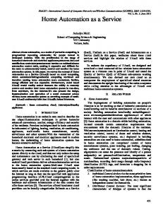
our test site. As presented in Fig.1, the system is composed of a microphone array, a front-end signal pre-processing block, which includes acquisition, filtering, and beamforming components, and speech processing modules such as the keyword spotter, speech and speaker recognition modules. The outputs of the recognition components feed the information extraction and concept retrieval modules, namely the user modeling and speech understanding modules, which were not integrated into the present set-up.
Fig.1. General architecture of the deployed system
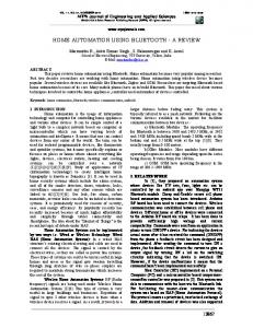
The functions of the system individual components and modules are briefly outlined in the following paragraphs: The acoustic signals that the microphone array acquires are processed in the front-end for localization and separation of the different sound sources that are active at a specific time segment. The front-end block serves the purpose of locating and delivering the target speech to the speech processing modules that follow by focusing on the speaker and, therefore, attenuating any other possible interference. The acquisition component receives the multi-channel signal from the microphone array through a sound card and captures the digital audio samples to form multi-channel audio streams. The filtering component consists of several pre-designed selectable filters, which when activated restrict the spectral contents of the input signal to a restricted bandwidth. Thus, most of the information required for correct speech and speaker recognition is retained. Significant parts of the low and high frequency components from the potential sources of interference are simultaneously excluded, such as music, noises from funs, refrigerators etc. The beamforming component is an essential element of the front-end. It has the task to locate the active speaker which is interacting with the system through a dialogue, while it attenuates the interference originating from other speakers and/or home appliances. The beamformer consists of two submodules: (a) DOA estimation and (b) signal separation. A simplified structure of a beamformer is illustrated in Fig. 2:
Fig. 2. Architecture of the beamforming process
As shown in Fig. 2, the direction of arrival of the source is estimated using the 8-channel audio data. This result is used as input by the signal separation algorithm, which produces an enhanced single-channel output audio signal, representing the speech coming from the source of interest. The word spotter excludes accidental commanding of the appliances by constantly seeking a specific word, the one that activates the agent. As long as the keyword is not detected the propagation of the signal to the speech and speaker recognition modules is obstructed. Characteristic examples of the permissible commands of the appliances are the following: “Agent could turn on the light, please!” “Agent, turn on the TV to channel four, please!” “Agent is the ventilator working?” One should have in mind that commands which are not preceded by the name of the agent (Agent in this example) are ignored. This rule was introduced as a safety measure. An appliance should not receive commands just because someone is talking about it. When the keyword is spotted, the speech that follows propagates to the speaker identification module. The speaker identification and user modeling modules are constituents of a composite personalization module, which plays an important role in the dialog generation process. The speaker identification module ensures that only authorized users have access to the system. In detail, every portion of the input speech is examined and accordingly labeled as speech originating from specific authorized user, or otherwise, as signal that does not belong to any of the authorized users. Speech from unauthorized people and signals which correspond to interference (which might have been missed out from previous stages of gating, e.g. music in the speech pauses) are discarded. In case of successful identification of any of the authorized users, the speech utterance that belongs to him/her is forwarded to the speech recognition module. The user modeling component is responsible for modeling the users’ preferences and keeping track of user-specific sequences of actions. When an authorized user is interacting with the system, specific settings for his profile are activated (e.g. adjust the volume of the speaker output according to the personal preferences, or ask a refining question in a specific way depending on the idiosyncrasy of the user). The speech recognition module consists of a continuous speech recognition component, which performs the main recognition process using a language modeling sub-module and the appropriate dynamically-built lexicons. In the present study, strict replication of the user’s speech word for word was
not required; instead the “task completion” criterion was accepted. A task is considered completed when the recognition engine provides a correct transcription of the speaker’s intention. The speech understanding component parses every phrase or sentence and generates the corresponding concepts, which feed the dialog generation module. Thus, the dialog generation flow operates on a conceptual level, which facilitates the handling of the variety of home appliances. In a larger scale implementation the intelligent home devices and the speech enabled interface will be integrated in a network, which controls the home appliances through hardware (see e.g., [8]). Although the hardware and software components of the system are tightly connected, the next Section III puts the accent on the software tools that were developed for the frontend block. Section IV describes the hardware that was deployed at our test site together with the specifics of the system integration. Details about the implementation of the speech processing modules are also provided. III. IMPLEMENTATION OF THE FRONT-END The front-end provides pre-processing and separation of the speech signal from interference. The essential components of the front-end are acquisition, filtering, and beamforming submodules, which process the signal in subsequent steps. Finally, the enhanced speech signal is delivered to the speech processing modules that follow the front-end. A. Acquisition component The acquisition component consists of multi-channel acquisition hardware and the corresponding software tool. This tool is responsible for capturing digital audio samples from the acquisition hardware, and thus, for producing synchronous multi-channel audio streams. Through a GUI, the tool facilitates selection of individual channels among installed audio devices when more than one pieces of acquisition equipment are accessible. Various user-definable audio formats (different sampling frequencies and audio sample resolutions) are available. The acquisition tool has been implemented as a dynamic link library (DLL) using low-level application programming interfaces (APIs) for creating multimedia applications. B. Filtering component The filtering component is a software tool that implements several band-pass, low-pass, and high-pass filtering algorithms. Although this tool appears less complex among other components in the front-end, its proper configuration and operation is crucial for the robust operation of the entire system. As illustrated in Fig. 3, every channel of the input audio stream is band-limited by a band-pass filter [300 Hz, 3400 Hz]. Thus, a significant part of the low and high frequency energy of any potential interference (e.g. refrigerator, ventilator, computer fans, etc.) is discarded. Every channel of the already band-limited audio stream is then pre-
emphasized through the pre-emphasis filter H(z)=1-0.97z
-1
(1)
This significantly improves the accuracy of the DOA estimation in reverberant environments. After the beamforming process is completed, the output signal is deemphasized by the filter H-1(z)=1/(1-0.97z-1)
Next, the beamformer’s output (single-channel audio signal) is de-emphasized. A finite number of filter coefficients is used for approximating the IIR de-emphasis filter (see equation (2)). The number of coefficients that was found to provide a sufficient approximation of the transfer response of the original IIR de-emphasis filter is equal to 200.
(2)
to restore the formant structure of the speech signal for the proper operation of the speech processing modules that follow. In fact, in a more compact integration of the entire system it is natural for the de-emphasis step to be omitted. However, the requirement that the audio stream is audible after each module was imposed for diagnostic purposes. The filtering tool is controlled through GUI application referenced to as filter selection tool. The filtering tool was developed in ANSI C programming language, while the filter selection tool was implemented in C++. C. Beamforming component The beamformer is an entirely software component that runs on a typical workstation. Fig. 3 provides a detailed flowchart for the filtering and beamforming tools. The band-limited and pre-emphasized multi-channel audio stream is firstly used for DOA estimation. Wideband DOA estimation is based on the fact that each frequency bin of the FFT of a block of a speech signal is considered a narrowband signal. By following the incoherent approach on per block basis we derive the histogram of all angles of arrival. By forming the distribution of the angles corresponding to all spectral coefficients the DOA of each speech frame can be calculated. In order to increase the robustness of the estimation procedure while decreasing the computational load we enforce the calculation of DOAs to be derived only from the frequencies possessing the highest power on per block basis. Spectral bins with low power are mainly due to noise or they are frequently corrupted by noise and thus tend to return fairly non-robust DOA estimates. DOA estimation schemes based on MUSIC and ESPRIT have a high computational cost due to the eigenvalue decomposition of the spatial correlation matrix. In our framework, the delay-and-sum [1] and minimum variance algorithms [2] have been implemented and tested. The minimum variance beamformer leads to more accurate results, whereas the delay-and-sum is less computational demanding. Following the DOA estimation process, the input signals are separated using the computed beamformer weights. The method for separating the signals, given the computed weights, is the same for both implementations of the beamformer (delay-and-sum and minimum variance) [1]. In order to compensate for distortions introduced to the first and last samples of each block at the previous stages of the beamforming process an auxiliary step, referred to as “fix the block borders” is performed. These distortions are corrected by applying an FIR filtering.
2 -
/ +
-
.
2 3 2 . 2 4 2 &, 4 ., , 0
! ""#$ % &
'$
! 01 () * +
,
"' -
2 -
/ +
-
.
!
-
.
2 3 2 . 2 4 2 4 ., % +
)
(
( /
Fig. 3. General flowchart of the real-time beamformer application
Finally, the output data are sent to a network adapter through a memory buffer, which is initialized during the start of the beamformer application. The beamforming tool was implemented mostly in ANSI C language. However, the communication sub-module which provides connection to the GUI through a TCP/IP link has been developed in C++. D. The Graphic User Interface A GUI which activates, initializes, and manages the connections among the separate components of the front-end has been developed. The GUI controls all the three applications of the front-end: acquisition tool, filter selection tool and beamforming tool. Screenshots of the GUI are shown in Figures 4 and 5.
Time display: total run time of the program
DOA text: the DOA values of the current block (divided into 4 sub-blocks).
DOA visual display: this is the mean value of the DOA of the 4 sub-blocks. Energy visual display: this is the mean value of the energy of the 4 subblocks. Fig. 4. GUI and Acquisition tool application while running
Fig. 5. Beamforming and filtering application while running
is smartly placed inside the room in a way that the loudspeakers of the TV set or audio equipment are placed outside its scan range. This practical procedure though simple in concept, greatly reduces the misclassifications of the recognition engine since the interference originating in TV or radio does not reach the recognizer as long as there is no speaker active inside the scan range. The word spotter can be assumed as a third stage of gating. Only after the name of the agent is detected the next modules of the system are activated to listen to the input speech. The forth stage of gating is the speaker identification process, which retains only that speech originating from anyone of the authorized users. Concurrent speech from nonauthorized people, a TV or radio broadcasts is discarded. Thus, the speech recognition module operates only with enhanced speech, which follows the agent’s name, and that is labeled as pronounced by an authorized user. A. Overall dimension of the set-up Since only general-purpose personal computers (PC) available at our test site were used in the proposed set-up, the workload of the system was distributed among several of these machines. We refer to these computers as workstations. As Fig. 6 illustrates, the acquisition, filtering, and beamforming components are installed on two different workstations and communicate through a TCP/IP link, either wired or wireless. The acquisition workstation is a PC with a typical 32-bit CPU operating at 1.6 GHz, while the beamforming workstation is a PC with a 32-bit CPU operating at 2.4 GHz. All speech processing modules are installed on a third workstation, a PC with 32-bit CPU operating at 1.6 GHz, which receives the audio stream from the beamformer workstation through another TCP/IP link.
After the input parameters in the acquisition, beamforming, and filter selection tools are selected, the GUI activates the connection between them. Then, the beamforming process is launched. A number of intermediate outcomes from the beamforming process are provided as a feedback to the GUI for visualization purposes (see Fig. 4 and Fig. 5 for details). IV. SYSTEM INTEGRATION The nature of the application entails that the recognition engine is active continuously. To prevent accidental activation/de-activation of appliances and a robust operation of the home automation system, a multiple-stage ‘gating’ of incoming signals (each stage functioning as a switch) is included in the design of the system. The first stage is a band-pass filter applied to each microphone channel. The second stage is composed of an adaptive spatial filtering array with a prefixed scan range (i.e. ±60o). If the source is detected outside the scan range of the array, the software switch turns off the input from the microphones and thus blocks the path to the recognizer. At this phase a general constraint is imposed on the array positioning so that the array
Fig. 6. Architecture of the deployed system
Rendering an account that 16 bits per sample are used, and that the sampling rate is 8 kHz, the amount of data which the 8-channel audio stream (transferred across the TCP/IP link between the acquisition and beamforming workstations) comprises is toting up to approximately 1 Mb/s. The speech processing workstation receives 128 kb/s, since during the beamforming process a single-channel audio stream is formed. Data rates of that range are available in the typical wired and wireless networks (e.g., 10/100BASE-T or 802.11b/g).
B. Front-End As Fig.6 illustrates, the microphone array is connected to the acquisition hardware accommodated on the first workstation. The multi-channel sound card that was employed in our set-up provides a minimum sampling frequency of 32 kHz at a resolution of 16 bit. Down-sampling to 8 kHz is employed for compatibility to the components and modules that follow. The 8-channel audio stream is delivered to the beamforming workstation through a TCP/IP link. The beamforming component is capable to run in offline or online mode: • Offline Mode: The audio data are obtained from 8 different files (one for each channel of the microphone array). • Online Mode: The audio data are captured directly through communication with the acquisition tool. While the offline mode was used solely for diagnostics purposes, the online mode is the typical operational mode of this tool. In our implementation the size of the input data blocks was determined as a trade-off conformable to the specific workstations used. Having in mind that the beamforming algorithm works with 512 sample FFT blocks, we found out that the minimum achievable input block size is 16 times the size of the FFT block. For that reason, the size of the input data block was set equal to 8192 samples. A reduction of the input block size reduces the acquisition time, but it also increases the computational demands. C. Word Spotting and Speech Recognition For the development of the word spotter and the recognition module that performs the main recognition task we used the HTK Hidden Markov Models toolkit [9] running simultaneously in different modes of operation. The basic recognition units are tied-state, context-dependent tri-phones of five states each. In order to train the acoustic models we used the Greek SpeechDat-II database of utterances and their associated transcriptions [10]. This database is a collection of Greek annotated speech data from 5000 speakers (each individual having a 12-minute session). We made use of utterances taken from 3000 speakers in order to train our system. Thirteen-dimension feature vectors are formed after applying DCT to log-filter-bank output which reduces the 20 output channels into 12-dimension Mel Frequency Cepstral Coefficients plus a log-energy value. Cepstral mean normalization is applied to deal with the linear channel assumption. The 13 aforementioned coefficients and their temporal regression coefficients of first and second order form the final 39-dimension observation vector. As regards the operation of the word spotter, the language modeling is based on word networks defined using the HTK Standard Lattice Format (SLF). An SLF word network is a text file, which contains a list of nodes representing words and a list of arcs representing the transitions between words. Thus the SLF file describes the network depicted in Fig. 7.
Fig. 7. The lattice of the word spotter
The words ‘!ENTER’ and ‘!EXIT’ constitute the start and end nodes of the network. The node ‘garbage model’ is a phoneme pool that points to a sub-lattice, which allows every combination of the language phonemes. Every possible transition among the agent’s name, silence (‘sil’) and the phoneme sub-lattice is permitted. Given the set of HMMs and the SLF file along with the corresponding dictionary, the HTK produces the best path of the word network using the Frame Synchronous Viterbi Beam Search algorithm. That is, the output of the HTK recognition unit will be any combination of phonemes and/or silence and/or the agent’s name. The word spotter will propagate the signal to the speaker verification and speech recognition modules only if the agent’s name is included in the output of the recognition unit. Regarding the recognition module the language models are also SLF word networks, the paths of which cover the most probable speaker utterances for the specific task. This was due to the lack of training data in the initial phases of development in order to create robust statistical models. However, in the following stages of system’s development it is anticipated that user utterances will be recorded and transcribed to be used for extending and improving the current language models. D. Speaker Identification The Speaker Identification (SID) component of the Personalization Module has as a main task to infer the identity of the speaker out of a small number of pre-registered voices. We have employed a Probabilistic Neural Network (PNN)based identification technique [11], [12]. The text-independent SID component has a modular structure with an individual PNN (see [14] for details about the PNN) for each authorized user. A common reference model, representing the non-users, is employed for counterbalancing the scores produced by the individual user models. For both the user and reference models, the available training data are compressed by using the k-means clustering technique [13], and the codebooks produced are further used for training the PNNs. In this way, the complexity of individual neural networks is greatly reduced and faster operation times are achieved. A codebook of 128-vectors for the enrolled users, and a codebook of 256vectors for the reference model were used. The size of the codebooks was chosen as a trade-off between computational
demands and performance. During each test, the probability that the input speech belongs to a particular authorized user is estimated. The Bayesian decision rule is applied to distinguish the user with the highest likelihood score. Finally, if this score is above a predefined speaker-independent threshold the speaker is accepted as an authorized user and his identity is announced, otherwise he is rejected as an impostor not belonging to the set of authorized users. E. Response time of the system In the present set-up, the total response time of the system is calculated as a sum of the delays of all components and modules. As Table 1 presents, the most significant delay is introduced by the front-end block. Since the beamforming tool was set to work with an input buffer of one second, a delay of 1 s is introduced in order the acquisition component to collect these data. TABLE 1: DELAYS INTRODUCED BY THE INDIVIDUAL COMPONENTS AND MODULES. TOTAL RESPONSE TIME OF THE SYSTEM
Module/Component name Front-End: Acquisition Filtering Beamforming Keyword Spotting Speaker Identification Speech Recognition Total response time
Delay [s] 1 >0.05 0.6 >0.1 0.3 0.3 2.3
The beamforming component has the highest computational workload and by that reason it is accommodated on a separate workstation. The beamforming process requires 0.6 s of computational time for a block of data of 1 s. The total delay of the speech processing modules is less than 0.6 s. Since in the present study the main focus is at the evaluation and development of the front-end pre-processing, the speech processing modules we used were taken ready “from the shelf”. Thus, their integration was not optimized for speed of operation. In a more integrated set-up the feature extraction steps of each speech processing module would be replaced by a single feature extraction step, which computes the speech features for all the modules. The total response time of the system was approximately 2.3 s, and was perceived by users as slightly annoying. Besides optimizing the module integration, a considerable decrease of the system delay is attainable when more powerful workstations are employed. While in the present section we successfully address the problem with tracking the position of moving users, a more advanced scheme which integrates feedback from the Speaker Identification module is required for scenarios where the interference has higher energy than the target speech.
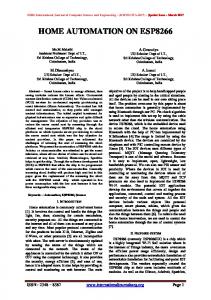
V. EXPERIMENTAL RESULTS Experiments in a real room have the advantage of testing a system in a situation close to the final operational conditions. However, the unconstrained number of speakers, their movement and the variability of the environment make quantitative analysis problematic in terms of recognition accuracy. Having this in mind, in the present section we try evaluating different aspects of the implemented algorithms, providing experimental results that supplement each other. A. Experimental setup The experiments took place in a 6.75 m × 4.9 m × 3 m room with reverberation time of approximately 0.3 s. Our passive acoustic array consisted of 8 omni electret condenser capsules Ø 9.7 mm and an multi-channel soundcard with internal preamplifiers, 8-channel A/D converter for the signal acquisition, and 0.10 m spacing between microphones. The signals were sampled at 32 kHz with 16 bits per sample and later down sampled to 8 kHz. All results reported in the present section were obtained by employing the minimum variance beamforming algorithm. B. DOA estimation results The performance of the entire system depends in significant degree on the efficiency of the front-end block, and more precisely, on the accuracy of the DOA estimation sub-module. To assess the DOA accuracy and robustness an experiment was performed in conditions close to a typical real-world situation. In this experiment a continuous speech (without large pauses) of a moving person recorded in a real room environment was utilized. As shown in Fig. 8, the speaker starts moving from the 180 degrees position and maintains a circular path to the 0 degree position.
Fig. 8. Experimental topology for real DOA estimation experiments
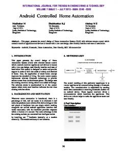
11, since the actual DOA is known it is straightforward to compute the signal attenuation in dB as a function of the actual DOA. 0
Power gain (dB)
The distance between the speaker and the microphone array was kept approximately equal to 2.5 meters. Furthermore, the speaker stops twice during the experiment: once at position 135 degrees (for 2 seconds) and once at position 90 degrees (for 3 seconds). Fig. 9 presents the actual DOA for the speaker and that estimated by the proposed implementation as a function of time. In Fig. 10, the absolute error of the estimated DOA when compared to the actual position is shown. The average absolute error for the specific experimental results is 3.66 degrees and the maximum value of the absolute error is 11.88 degrees. Furthermore, when the speaker’s position does not change for a short period of time, the error of the DOA estimation process is almost equal to zero – in our experimental set-up this occurs at positions 90o and 135o.
-5
-10
180 -15 0
Actual DOA Estimated DOA
160
DOA (degrees)
60
80
100
120
140
160
180
Fig. 11. Power gain as a function of DOA
120
The signal attenuation obtained in this experiment conforms to theoretical results, showing an increasing attenuation trend, approximately 3 dB and at least 12 dB for positions that are respectively 15 and 45 degrees away from the 90o direction. These results show that the beamforming process is quite efficient at attenuating signals coming from different directions than that of interest in a real home environment, deeming this component suitable for the proposed application.
100 80 60 40 20 0
5
10
15 20 Time (seconds)
25
30
Fig. 9. Actual and estimated DOA 12
10
Absolute error (degrees)
40
Angle (degrees)
140
0
20
8
6
4
2
0 0
20
40
60
80
100
120
140
160
180
Actual DOA (degrees)
Fig. 10. An absolute error between the actual and estimated DOA
C. Signal separation efficiency estimation Although the experimental topology for evaluating the signal separation is the same as in the DOA estimation step, DOA estimation does not take place in this experiment: In order to verify the system’s ability to attenuate signals coming from different directions than the DOA of the strongest signal, a constant 90 degrees DOA is assumed. As presented in Fig.
D. The Speaker Identification Task In our setting only ten persons – five male and five female speakers were authorized to access the system. Therefore, due to the nature of the application the workload of the SID is rather light compared to the number of speakers contemporary speaker recognition systems can identify. A common protocol was followed in all SID experiments. The training data consist of six dialogues that provided approximately 30 seconds of voiced speech per authorized user. The test data comprise 15 utterances per user, obtained in three separate dialogues. In total, the ten users performed 150 test trials. In the first experiment, we evaluated the speaker identification accuracy for two specific static positions of the user: 90o and 135o with respect to the position of the microphone array. Fig. 12 presents the identification accuracy in percentages depending on the SNR conditions. Modern Greek music waveforms were played as interference in these experiments. The experimental results imply that in all SNR conditions position 90 degrees is more favorable than position 135 degrees. Regardless of the performance deterioration for the lower SNR scenarios, the beamforming algorithm was able to reduce the interference even for the most adverse conditions: 0 dB SNR and –6 dB SNR.
Accuracy [%]
100 90 80 70 60 50 40 30 20 10 0
90 degrees 135 degrees
20 dB
10 dB
0 dB
-6 dB
SNR conditions [dB]
Fig. 12. Speaker Identification performance for two positions of the target speaker in various SNR conditions
Three scenarios were investigated. Firstly, four people discussing while seated in the room (quiet conditions). Secondly, three people walking engaged in conversation (quiet conditions) and, finally, three people walking engaged in conversation while music was on. One person had access to the system and commanded the appliances using phrases on the basis of twenty commands of the form: . The users were informed if the task completed by success or failure by projecting the computer screen on the wall. Each user performed 3 sessions. Table 2 summarizes the results from the speech recognition experiments TABLE 2: MEAN TASK COMPLETION RATE (IN PERCENTAGE) WITH RESPECT TO NUMBER OF TRIALS. EACH TRIAL IS COMPOSED OF A FULL SET OF 20 COMMANDS.
To evaluate the ability of the beamformer to follow moving targets, two experiments assessing the SID performance for moving speakers were performed. In the first one, the SID models were trained with clean speech recorded from stationary speakers and then tested with utterances from moving speakers. An identification rate of 92.0 % was obtained. In the second experiment, the SID models were trained with the same utterances as in the previous experiment but pronounced when the talkers are moving around the room. As expected, a higher identification rate of 96.7 % was observed due to the matching test and training conditions. For the sake of completeness, we carried out a reference experiment with a high quality close-talk microphone carrying a built-in adaptive noise cancellation instead of our microphone array, and we obtained an identification accuracy of 99.3 %. After analyzing the results from the two experiments that involved moving speakers with respect to the result from the reference experiment, we concluded that: (a) the drop of 2.6 % in the SID accuracy for the models trained with speech from moving speakers, when compared to the reference one, is mainly due to some ambient noise introduced by the equipment deployed in the room and the users themselves. (b) the additional drop of 4.7 % that was observed when user models were trained with clean speech from stationary speakers and then tested with speech from moving talker, is due mainly to change in the actual SNR of the input speech signal, caused by the constant variation of the position of the speaker, and also to reverberations of the speech from the walls of the room. In both experiments involving moving speakers, the beamforming algorithm performance was found to be satisfactory: compared to the close-talking microphone scenario, only a minor reduction of the identification accuracy by 2.6 % was observed for the matched test and train conditions.
As Table 2 presents, very high task completion rates were achieved in all test scenarios. In the first scenario, in 96 % of the cases the task was accomplished successfully on the first trial and only in 4 % of the cases the user had to repeat his/her request. In the second scenario, a noticeable reduction of the task success rate was observed. This reduction is due to two factors: firstly, to the decreased SNR conditions – due to the wooden floor, the users were introducing creaking noises while walking; secondly but more importantly, most of the users were not facing the microphone array while walking – thus, actual path of the speech signal was varying constantly due to reverberations. In addition, it was observed that compared to the steady position some of the users changed their speaking style while walking. The introduction of interference (music) in the third scenario, although slightly reduced the task completion rate, did not affect the performance of the system badly. Comparing the reduction of performance between scenarios two and three to the one observed between scenarios one and two, we can conclude that the users’ behavior affected the performance more strongly than the introduction of interference. In conclusion, we would like to emphasize that the effective functioning of the front-end determined the robust operation of all speech processing modules that were tested. In case that the beamforming component is excluded from the front-end block, and a single microphone is used for audio acquisition, the word spotter activated sporadically, and the speech and speaker recognition modules fail to provide a useful performance.
E. The Speech Recognition task In the evaluation of the system’s performance we relied on the task completion criteria. A group of ten potential users was used in the experiments.
We presented a robust combination of a number of diverse technologies, to construct a speech activated portal to complex devices to assist users who are disabled or not technically-
SCENARIOS 1st 2nd 3rd
Task Completion Rate (%) 1st Trial 2nd Trial 3rd Trial 96 100 85 92 96 79 84 90
VI. CONCLUSION
inclined at home or in their workplace. We sought to frame the problem in a manner that departed from the highly constrained laboratory settings towards real-life operational conditions. The system integrated a linear microphone array to supply spatial sound selectivity, a word spotter that provides a robust gate to the far-end speaker recognition system, a speaker recognition module that allows interaction of only registered users and finally a speech recognition system. Future work on the problem will focus on robust stochastic models based on back-off n-grams. Moreover, all appliances will be connected in a network and the line-out of TV and audio equipment will serve as an accurate noise reference to the ANC. The possibility of wireless arrays is also to be investigated.
Theodore Giannakopoulos was born in Athens, Greece in 1980. He received an Informatics and Telecommunications degree from the University of Athens in 2002 and an M.Sc. Diploma in Signal and Image Processing in 2004 from the University of Patras. He is currently working on his Ph.D. thesis at the Dept. of Informatics and Telecommunications, University of Athens. His research interests are stochastic signal processing, pattern recognition and content-based multimedia indexing Nicolas Alexander Tatlas was born in Athens, Greece in 1978. He received an Electrical Engineering and Computer Technology degree from the University of Patras in 2001. He is currently working on his Ph.D thesis. His main research interest is in the area of digital audio distribution networks and in room acoustics simulation and analysis.
REFERENCES [1] Brandstein, M. and Ward, D., (Eds.), “Microphone Arrays Signal Processing Techniques and Applications”, Springer-Verlag, 2001. [2] Krim, H. and Vibeg, M., “Two Decades of Array Signal Processing Research”, IEEE Signal Processing Mag., 1996. [3] Johnson, D. and Dudgeon, D., “Array Signal Processing: Concepts and Techniques”, Prentice Hall, 1993. [4] Brandstein, M., “A Framework for Speech Source Localization Using Sensor Arrays”, PhD thesis, Brown University, Providence, RI, 1995. [5] Brady, P., “A technique for investigating on-off patterns of speech”, Bell Syst., Technical Journal, 44:1-22, 1965. [6] Griffiths, L. and Jim, C., “An alternative approach to linearly constrained adaptive beamforming”, IEEE Trans. Antennas and Propagation, 30(1):24-27, 1982. [7] Hoffman, M., Pinkelman, C., Lu, X., and Li, Z., “Real-time and off-line comparisons of standard array configurations containing three and four microphones”, Journal of the Acoustical Society of America, 2000. [8] http://home-automation.org/Home_Networking/ [9] Young, S., et al., “The HTK Book”, Entropic Cambridge Research Laboratory, Cambridge, 1997. [10] Van den Heuvel H., Moreno, A., Omologo, M., Richard, G., Sanders, E., “Annotation in the SpeechDat projects”, International Journal of Speech Technology, 4(2):127-143, 2001. [11] Ganchev, T., Fakotakis, N., Kokkinakis, G., “Text-independent speaker verification based on Probabilistic Neural Networks,” in Proc. of the Acoustics, Patras, Greece, pp. 159-166, 2002. [12] Ganchev, T., Fakotakis, N., Kokkinakis, G., “One-Speaker Detection – Limited Data: The WCL-1 System,” presented at the 2003 NIST Speaker Recognition Workshop, College Park, MD, USA, June 24-25, 2003. [13] J.A. Hartigan, M.A. Wong, “A k-means clustering algorithm”, Applied Statistics, 28(1), pp. 100-108, 1979. [14] Specht, D.F., “Probabilistic Neural Networks”, Neural Networks, 3(1), pp. 109-118, 1990.
Todor Ganchev (S’96-A’99-M’02) received Diploma Engineer degree in Electrical Engineering from the Technical University of Varna, Bulgaria, in 1993. From February 1994 to August 2000, he consequently held engineering, research, and teaching staff positions at the same University. Since September 2000, he is with the Wire Communications Laboratory, University of Patras, Greece, where in February 2001 he started his Ph.D. study in the Speaker Recognition area. Ilyas Potamitis received the B. Eng. and Dr. Eng. degrees in Electrical Engineering from the Department of Electrical and Computer Engineering, University of Patras, Greece in 1995 and 2002, respectively. During 1998-2002, he joined Wire Communications Laboratory (WCL), Department of Electrical and Computer Engineering, University of Patras, Greece pursuing his doctoral degree study. His research area is speech enhancement and speech feature extraction for robust speech recognition. He has more than 20 publications in refereed journals and conferences.