Network Protocols and Algorithms ISSN 1943-3581 2013, Vol. 5, No. 2
A Precise Indoor Localization Approach based on Particle Filter and Dynamic Exclusion Techniques Mohammed Elbes Dept. of Computer Science, Alzaytoonah University of Jordan Amman, Jordan Tel: +962-798314584
E-mail:
[email protected]
Ala Al-Fuqaha Computer Science Department, Western Michigan University Kalamazoo, MI Tel: +(269) 276-3868
Email:
[email protected]
Muhammad Anan Electrical and Computer Engineering, Purdue University-Calumet Tel: +1(219) 989-2483
Received: May 17, 2013 DOI: 10.5296/npa.v5i2.3717
Email:
[email protected]
Accepted: June 18, 2013
Published: June 30, 2013
URL: http://dx.doi.org/10.5296/npa.v5i2.3717
Abstract Indoor localization with a significant degree of precision is extremely challenging. In this paper, we present a precise indoor localization approach based on novel particle filter and dynamic exclusion techniques. The approach is compared with the Euclidean Distance probabilistic methods used for localization. The novelty of the proposed approach stems from its ability to fuse data collected from different sensor technologies to converge to more accurate distance estimation. Furthermore, the proposed approach is a pattern-based one that relies on empirical training data as opposed to closed-form mathematical models. Keywords: Indoor Localization, Particle Filter, Location Fingerprinting, Data Fusion, RSSI. 50
www.macrothink.org/npa
Network Protocols and Algorithms ISSN 1943-3581 2013, Vol. 5, No. 2
1. Introduction and Related Work The main goal of localization is to track moving objects. Localization can be performed in buildings and closed environments (indoor localization) or outside buildings (outdoor localization). Many surveillance and tracking applications rely completely on the knowledge of the position of objects in the environment. These applications provide a new layer of automation called automatic object location detection [1]. Real world applications depending on this automation process are numerous. Location detection of personnel or medical equipment inside a hospital, moving assets inside a store, location detection of firemen inside a building on fire, intelligent guidance, location-aware multimedia services are examples of these applications [2-4] . The majority of tracking applications is based on triangulation and lateration techniques using light [5, 6], ultrasound [7, 8], or radio signals [9-12]. Other techniques use inertial navigation to provide relative object location detection [13, 14]. Unfortunately, these techniques suffer from drifting and error accumulation resulting from noisy data integration over time, which requires continuous and periodic system calibration to reset the system state. Available systems with different configurations and accuracies are currently being used worldwide. AT&T Cambridge Ultrasonic Bats [5], Microsoft Research’s WaveLAN system [15], Active Badges [16], Radio tags, Computer vision systems [17], are examples of such systems. The complexity of indoor environments resulting from multipath propagation and frequent environment changes requires using more than one technique to improve localization accuracy. Data from wireless LANs, Ultra Wide Band (UWB), Infrared (IR), Ultrasound, camera images and Inertial Measurement Units (IMUs) were fused by multiple data fusion techniques to provide more precise and robust localization systems [18-22]. These systems are evaluated based on location accuracy, cost, range, and the data rate. Tradeoffs between these evaluation parameters exist in each of these systems. Kalman filter is used in most of the data fusion techniques. Its main assumption, i.e. the linear model, can be hardly fulfilled in real life. Extended Kalman Filter (EKF) [19, 20] and Unscented Kalman Filter (UKF) [18] have been proposed to solve the non-linear estimation problem by linearizing all the non-linear models. These filters are only reliable for almost-linear systems. Distributed information like the map information is impossible to be integrated for tracking by EKF or UKF. As an alternative to Kalman filter and its derivatives, Particle Filter (PF) is getting more attention recently [19]. The authors in [20] proposed a Location Constrained Particle Filter (LC-PF) based approach to perform indoor localization using RSSI measurements. The proposed techniques include Location-Constrained Weight Updating (LC-WU) and propagation model (LC-model). This model eliminates particles in prohibited regions based on the geolocation of the map. The proposed methods can be applied separately or jointly. The experimental results in [20] shown that the two models are effective and provide a location error of less 51
www.macrothink.org/npa
Network Protocols and Algorithms ISSN 1943-3581 2013, Vol. 5, No. 2
than 2.5m. In this paper, we present a novel approach for performing data fusion between multiple sensor technologies including accelerometers, gyroscopes, Wi-Fi, and Time Difference of Arrival (TDoA) sensors to achieve precise localization in indoor environments. The proposed Inertial Navigation System (INS) is comprised of tri-axial accelerometer, gyroscope and an MIT Cricket system for gyroscope drift correction. The INS system provides the distance that the moving object travelled and the direction of that distance. Section 2 of this paper provided a brief introduction about indoor localization and the related work. The rest of the paper is organized as follows; section 2 presents the probabilistic methods used in indoor localization. Our proposed approach to indoor localization is provided in section 3. The simulation setup and a discussion of our simulation results are presented in section 4 and the paper concludes in section5.
2.
Background
Location fingerprints is an offline collection of features collected from the localization network. Location fingerprinting refers to the process of matching the fingerprint of some characteristic of the signal that is location dependent. This can be done in two stages [21]: Offline: in this stage, a site survey is performed to collect a known location coordinates/tags with their respective signal strengths from nearby transmission towers. These measurements are stored in a location fingerprint database to be used in the online stage. Online: during this stage, the localization technique uses the offline data stored in the location fingerprint database along with the online Received Signal Strength Indicator (RSSI) measurements to estimate the object position. The main challenge for this technique is that the signal strength is affected by diffraction, reflection and scattering in indoor environments [1]. The location fingerprints database contains N fingerprints with each location fingerprint representing the RSSI measurements observed from M nearby access points. The database structure is shown in “Table 1”. The table has two columns, the RSSI measurements vector and the corresponding location ID at which these RSSI measurements are observed. A location fingerprint FPi at location i can be represented by: FPi= { , , ,…, }.
52
www.macrothink.org/npa
Network Protocols and Algorithms ISSN 1943-3581 2013, Vol. 5, No. 2 Table. 1: The fingerprint database structure
Fingerprint FP1= {
,
,
,…,
}
FP2= {
,
,
,…,
}
Location = (X1,Y1) = (X2,Y2)
…
…
FPN= {
,
,
,…,
= (XN,YN)
}
By using the Euclidean Distance (EUC) technique, the object localization is treated as a classification problem. Given N location fingerprints and an online RSSI vector (S) for the moving target T, where S = {
,
,
, … ,
}, the Euclidean distance
between S and FPi is given by [21]: =
(1)
Where M is the number of access points. The probability that the object is near fingerprint FPi given the measured RSSI vector S is given by: P(FPi|S) =
(2)
Then the location decision rule becomes [1]: Choose if P(FPi |S) > P(FPj |S), where is the location of FPi, for ∀ i, j = 1, 2, 3, . . . , N, j i. Assuming that the probability that the tracked object is at location is given by P( ) and assuming that P( ) = P( ) for i, j = 1, 2, 3, . . . , N, j i. Using Bayes’ theorem we have the following decision formula based on the likelihood that P(S|FP i) is the probability that the signal strength is S provided that the tracked object is at location : Choose
if P(S|FPi) > P(S|FPj), for ∀ i, j = 1, 2, 3, . . . , N; j
i.
Based on the fact that the measuring units in the localization area are independent, the overall likelihood of the target location can be calculated from the observed signal strengths during the online stage. Hence, the tracked object location can be estimated using the previous decision rule. However, this can be applied only for discrete location candidates. In reality, the tracked object can be at any position in the network and not only at discrete locations. Thus, the location LT of the tracked object can be interpolated by a weighted average of the locations of all location fingerprints in the database using the equation: 53
www.macrothink.org/npa
Network Protocols and Algorithms ISSN 1943-3581 2013, Vol. 5, No. 2
LT(x,y) =
(3)
where x,y are the coordinates of FPi . “Fig.1” provides the Pseudo code for the EUC approach for indoor localization: N : Number of location fingerprints M : Number of access points D: distance between a location fingerprint and the tracked object. FPw : Weight assigned to a given fingerprint W : Summation of all location fingerprint weights F = Multiplication factor S : The current RSSI vector for the tracked object LT: Estimated location of the tracked object expressed by LTx, LTy : Location of fingerprint i expressed by LTx=0
LTy=0
and
W=0
For i = 1 To N Compute Di using “(1)” FPwi =
W=W+FPwi End For F = 1/ W
Figure1. Pseudo code for the EUC approach.
For i = 1 To N
A static location fingerprint exclusion technique was demonstrated in RADAR [9] using = F * FPwi the K-Nearest Neighbors (KNN) algorithm. The idea behind this approach is that only a specific set of location fingerprints are used in the location estimation. Only K nearby LTx= LTx + * fingerprints contribute to location estimation based on their RSSI distance from the tracked object. The results in [9] shown that a small value of K induces higher location error. The LTy= LTy + * error becomes smaller as more nearby location fingerprints are added to the set of the End For Adding further location fingerprints increases the location contributing location fingerprints. error again. The drawback of this approach lies in the difficulty to determine the value of K that offers minimum location error for a certain localization environment. In this paper, the performance of the proposed localization technique using Budgeted Dynamic Exclusion (BDE) is compared with existing approaches using the Euclidean Distance methods. Further localization accuracy is achieved by fusing INS data with RSSI measurements using the particle filter.
54
www.macrothink.org/npa
Network Protocols and Algorithms ISSN 1943-3581 2013, Vol. 5, No. 2
3. Proposed Approach In the EUC approach, the weight of a given location fingerprint in estimating the tracked object location completely depends on the RSSI differences between the location fingerprint and the tracked object. All access points are involved in computing the RSSI distance between a specific location fingerprint and the RSSI vector of the tracked object according to “(1)”. The proposed approach aims to identify the outlier access points and exclude them from the position estimation process to gain more localization accuracy. Further localization accuracy is gained by fusing the RSSI data with data from the INS using the Particle Filter. The following sections discuss the proposed indoor localization in detail. 3.1 Budgeted Dynamic Exclusion (BDE) Heuristic in Support of Indoor Localization In the BDE heuristic, we aim to exclude the RSSI values from the outlier access points while computing the distance between an RSSI vector retrieved from the location fingerprint database and the RSSI vector measured by the tracked object. This is done by comparing the RSSI value from the jth access point in the ith location fingerprint with the corresponding RSSI value ) from the jth access point in the RSSI vector of the tracked object. If the difference between these two RSSI values is less than certain budget, the corresponding access point (the jth access point) will be excluded from the RSSI distance measurement process “(1)”. If the tracked object is close to a certain location fingerprint, the corresponding RSSI values on both of them are most likely less than the budget. Hence, more access points will not be involved in “(1)” and consequently that location fingerprint will have more weight in the location estimation process according to “(1)” and “(2)”. This means that only RSSI values from non-outlier access points which conform to the budget constraints are involved in the location estimation process. BDE starts with small value for the budget, (i.e. 5%) and computes the Euclidean Distance from all access points in a location fingerprint. A new distance is calculated based on the criteria described above. If the change in the new calculated distance compared with the previously computed Euclidean Distance is also greater than the budget, we increase the budget to achieve more access point exclusion. Otherwise, the system returns the last distance as the distance between the current fingerprint’s RSSI vector and the tracked object’s RSSI vector. This process is further described in the following steps: “Fig. 2” provides the Pseudo code for the BDE approach for indoor localization:
55
www.macrothink.org/npa
Network Protocols and Algorithms ISSN 1943-3581 2013, Vol. 5, No. 2
N : Number of fingerprints M : Number of access points D: distance between a fingerprint and the tracked object. FPw : Weight assigned to a given fingerprint W : Summation of all fingerprint weights F = Multiplication factor S : The current RSSI vector for the tracked object LT: Estimated location of the tracked object expressed by LTx, LTy : Location of fingerprint i expressed by LTx=0
LTy=0
and
W=0
For i = 1 To N Compute Di from “(1)” For budget = 5% To 25% StepBy 5% For j=1 To M If (
-
)/
D=D+(
-
> budget
)2
End if End For If (D-Di)/Di > budget Budget = budget+5% Else Di = D D=0 Break End if End For FPwi = Figure 2. Pseudo code for the EUC approach. W=W+FPwi End application For 3.2 Particle Filter (PF) in Support of Indoor Localization F = 1/ W
In addition to the Sequential Monte Carlo (SMC) nature of estimation, the PF allows for For i = 1 To N flexible design and parallel implementation. The main advantage of the PF is its ability to F * FPwiconsidering their probabilistic behavior. The key combine measures from multiple=sensors idea behind the PF is that the posterior Probability Density Function (PDF) of state x(k) is LTx= LTx + * measurements Z(k) according to the equations directly estimated conditioned on the set of [22]: LTy= LTy + End For
* 56
www.macrothink.org/npa
Network Protocols and Algorithms ISSN 1943-3581 2013, Vol. 5, No. 2
P[x(k)|Z(k)] ≈
(4) (5) is the weight of the ith particle
Where N is the number of particles is the Dirac distribution.
and
The biggest advantage of using the PF instead of the EKF is its ability to solve non-linear and non-Gaussian estimation problems. Many versions of the PF are available in the literature; in the proposed approach we use the SIRPF. This algorithm comprises the following steps [22] : 1- Particle Generation: generate N { , , , …, according to the initial PDF p(x(0)). 2- Prediction Sampling : for each particle , propagate the to the transition PDF p[x(k+1)|x(k)] 3- Importance Sampling : for each particle
} initial particles particle according ,
generate
the
4- Normalization and Rejection Sampling: The weights of the particles are normalized. Particles with low weight are deleted and particles with high weight are duplicated such that each particle has the same weight. In our work, the dynamics of the particle filter are controlled by the data from the INS and the RSSI location fingerprints. If the tracked object’s position was estimated at time k, the position estimation at time k+1 is guided by the INS to generate particles in the direction given by the INS. For each particle = [ xi(k) yi(k) ], the next particle can be obtained by: xi(k+1) = xi(k) + d cos (ϴ) + N(µ,σ)
(6)
yi(k+1) = yi(k) + d sin (ϴ) + N(µ,σ)
(7)
Where d is the absolute distance traveled by the tracked object during the time interval [k, k+1] and ϴ is the direction of d. For each particle = [xi(k), yi(k)], the RSSI distance between the closest location fingerprint to and the tracked object is calculated. The smaller this distance, the higher weight will have. =
Where
(8)
is the closest location fingerprint to particle
57
. Hence, the weight
www.macrothink.org/npa
Network Protocols and Algorithms ISSN 1943-3581 2013, Vol. 5, No. 2
of
is given by:
=
(9)
“Fig. 3” shows our overall localization system architecture which has three main components, the Inertial Navigation System (INS), the location fingerprints database and the particle filter for data fusion.
Figure3. The overall localization system architecture.
3.3. Mathematical Error Analysis for Indoor Localization In this section, the error analysis for indoor localization is addressed. Mathematical bound analysis on the position error in the proposed localization approach is also described in this section. The analysis is based on RSSI measurements observed at the tracked object’s location, the RSSI measurements on the Location Fingerprints (LF) around the localization estimate (PE), and the INS data obtained from the proposed INS subsystem. The localization accuracy is defined as the probability that the tracked object is within a certain distance (D) from its real location. Obviously, the closer the physical distance between the LF and the tracked object, the more weight that LF will have. The weight assigned to a given LF is composed of two parts:
58
www.macrothink.org/npa
Network Protocols and Algorithms ISSN 1943-3581 2013, Vol. 5, No. 2
Weight based on INS data. Weight based on RSSI measurements.
The region of confidence around the location estimate is described as a circle. The probability that the tracked object is within this circle is calculated based on the weights of the LFs around the location estimate (PE). For example, if the required localization accuracy equals 90%, we find the area of the circle such that the percentage of the LF weights that lies within this circle equals to 90% of the total weights of all LFs in the localization area. “Fig. 4” shows a snapshot of the localization area at a given time. The localization area shown in “Fig. 4” has M Transmission Towers (T), N circles around the localization Position Estimate (PE) and K location fingerprints on each circle. LFn denotes the LF on the nth circle. denotes the distance between the LF on the nth circle and the mth transmission tower. m denotes the angle between the mth transmission tower and the positive x-axis. The radius of the inner circle is denoted by R which is also equal to the distance between any consecutive circles. 3.3.1 RSSI-based Weight Analysis The signal strength estimation between the tracked object and any access point is expressed in terms of the mean path loss and a log-normally distributed noise. The mean path loss at a given distance is given by: (d)[dBm] = PL(d0)[dBm] + 10 * v * log10( )
(10)
Figure. 4. A snapshot of the localization area with the previous location estimate included.
59
www.macrothink.org/npa
Network Protocols and Algorithms ISSN 1943-3581 2013, Vol. 5, No. 2
Where PL(d0)[dBm] is the path loss at a 1 meter distance in free space which is about -20 dBm [23], d0=1 m, and v is the mean path loss exponent and indicates how fast path loss increases with distance. The RSSI at a given distance is then given by: (d)[dBm] + Xσ [dBm]
RSSI =
(11)
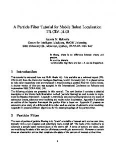
Where Xσ is a zero mean log-normally distributed random variable with standard deviation σ in decibels. The values of v and σ are suggested in [24] based on empirical experiments for various environments. In the proposed path loss model, we chose v=4.04 and σ = 4.3 for an office building. “Fig. 5” shows the RSSI values against distance in meters.
Figure 5. The RSSI values at various distances.
Given N LFs and an online RSSI vector (S) for tracked object T, where S = { , , ,…, }, the Euclidean distance between S and LFn RSSI vector is given by: =
(12)
Where M is the number of access points. To show how the weight based on the RSSI of the nth LF changes with the distance from the position estimate PE, we represent this weight in terms of the radius of the n th circle and the distance between PE and the M access points in the localization area. A single RSSI measurement from access point i at the tracked object location is denoted by [24]:
= PL(d0)[dBm] + 10 * v * log10( Where
) + Xσ
(13)
is the distance between the position estimate (PE) and the ith access point. 60
www.macrothink.org/npa
Network Protocols and Algorithms ISSN 1943-3581 2013, Vol. 5, No. 2
As we showed in the previous section, the distance between the nth location fingerprint and the ith access point is denoted by: =
(14)
Hence, the RSSI value on the nth location fingerprint from measured from the ith access point is denoted by: =PL(d0)[dBm]+10·v·
+Xσ
(15)
The Euclidean distance between the online RSSI vector of the tracked object and the RSSI vector of the nth location fingerprint is given by: =
(16)
The non-normalized weight based on the RSSI measurements of the nth LF is then given by: w=
=
(17)
The normalized weight based on the RSSI measurements of the nth LF is then given by: =
(18)
3.3.2 INS- based weight analysis Instead of finding the position estimate based on RSSI values only, the INS subsystem guides the future position estimate with certain distance and direction. We define the LF’s normalized INS weight ) based on how close it is from the position estimate: =
(19)
3.3.3 Combined-Weight Error Analysis As a result of data fusion, the generic total weight of a given location fingerprint is calculated by combining the weights from the two approaches explained in the previous sections ( ). The best combination approach is to multiply these normalized weights to get the total weight of LF: wn =
(20) 61
www.macrothink.org/npa
Network Protocols and Algorithms ISSN 1943-3581 2013, Vol. 5, No. 2
Let W be the summation of the location fingerprints weights along the positive x-axis: W=
(21)
Where N is the number of LFs on the positive x-axis. Our goal is to find the value of n such that a certain percentage (P) of W lies within the n circle. In other words we want to find n such that: th
= P*
(22)
Based on “(18)”, “(19)” and ”(20)”, it is difficult to find a deterministic solution for equation (22), we will use linear approximation to find a function En approximating wn such that En ≥ wn , n {0,1, …, N-1}. Theorem 1: The required localization accuracy defined as the probability (P) that the tracked object is within a certain distance D is guaranteed by the approximation function En. Proof: The value of wn expressed in “(20)” decreases as the value of n increases which means that farther LFs have less weight than those who are close to the position estimate. This means that the function wn is a decreasing function of n. The goal of linear approximation is to find a linear function that approximates the increasing function qn = 1/wn : qn=
(23)
The line (Ln) approximating qn is required to have values such that Ln ≤ qn ∀ n {0,1, …, N-1}. This guarantees that our approximation to wn (En), will always be greater than wn ∀ n {0,1, …, N-1}. “Fig. 6” shows an example of qn and Ln and “Fig. 7” shows the corresponding wn=1/qn and En=1/Ln. The goal now is to find the linear approximation function (Ln) with the properties mentioned above. Since Ln is a line, it can be written as: Ln = A.n+ B
(24)
Where A is the slope of Ln and B is the point where Ln intersects with the positive y-axis. Since Ln ≤ qn, this means that B can be equal to q0, which is the point at which qn intersects with the positive y-axis (see “Fig. 6”). After finding B, the objective becomes finding the slope of Ln that guarantees no intersection between Ln and qn ∀ n {1,2, …, N-1}. qn is an increasing discrete function with values in [w0 : wN-1].
62
www.macrothink.org/npa
Network Protocols and Algorithms ISSN 1943-3581 2013, Vol. 5, No. 2
Figure 6. An example of qn and Ln
“Fig. 8” shows the slopes of all lines connecting pairs (wn,wn+1) ∀ n {0,1, …, N-1}. Choosing the slope with minimum value guarantees that will not intersect with qn ∀ n {1,2, …, N-1}. After finding the line Ln=An+B, the function En (“Fig. 7”) that will approximate wn is of the form: E =1/L
=
(25)
The analysis of this function is much easier than wn in equation (20). To find the nth circle at which lies in a percentage (P) of the total weight (W) is at least equivalent to finding P of the area under the curve En. Since En≥wn ∀ n {0,1, …, N-1}, finding P of the area under the curve En implies finding P or more of the area under wn. This guarantees that the localization accuracy will be more than P that the tracked object is within a certain distance.
63
www.macrothink.org/npa
Network Protocols and Algorithms ISSN 1943-3581 2013, Vol. 5, No. 2
Figure 7. The required approximation function and the real wn.
Figure8. The slopes between all values of qn
3.3.4 Distance Estimation To find the value of n at which lies P percentage of the area under En, compute the total area under En and then find the P percentage of that area. The area under En can be found by: AEn =
AEn =
-
AEn=
(26) 64
www.macrothink.org/npa
Network Protocols and Algorithms ISSN 1943-3581 2013, Vol. 5, No. 2
Where N is the total number of LFs on the positive x-axis. The value of n at which Pth percentage of the area under En is: = P* AEn
=P*
=
=
n=
(27)
After finding the value of n, the distance (D) at which exists P percentage of the total weight W is equal to: D=n*R
(28)
Where R is the radius of the inner circle around P E. Our approximation algorithm can be summarized in the following steps: 1- Find the values of wn ∀ n {0,1, …, N-1} using equation (20). 2- Set B = w0. 3- SetA=
4- Find n =
.
5 - Find D = n*R.
4. Simulation Setup and Results Although a conclusion may review the main points of the paper, do not replicate the 65
www.macrothink.org/npa
Network Protocols and Algorithms ISSN 1943-3581 2013, Vol. 5, No. 2
abstract as the conclusion. A conclusion might elaborate on the importance of the work, suggest applications and indicates advantages, limitations, and possible applications. The simulation was performed in a 10x10 m room. The simulation starts by setting up the access points uniformly in the simulation area. The training data (location fingerprints) are then spread uniformly across the area. “Fig. 9” shows the distribution of 2 access points and 35 location fingerprints in the simulation area. The particles in the PF are divided into two groups: explorers and exploiters. About 20% of the particles are generated with high value for µ= 10 m to allow the particle filter converge quickly and prevent it from moving away from the optimal solution. The other 80% of particles are exploiters for the best possible solution.
Figure 9. Distribution of access points and fingerprints in the simulation area.
As the tracked object moves in the simulation area, the position is calculated using the EUC, BDE and PF techniques. The position estimated by these techniques is then compared with the simulation position of the tracked object. The simulation was executed for three hours and then replicated for 10 times. The accuracy of the INS subsystem is assumed to have an average error of 5 cm. In our work, we used IMUSim [25] as our simulation environment. IMUSim simulates sensor readings based on continuous trajectory models, and shows how suitable models can be generated from existing motion captures or other sampled data [26]. The input to IMUSim is a motion capture file [26] that describes the motion trajectories of a moving subject. The output can be chosen to be the accelerometer, gyroscope or magnetometer signals from the IMUs attached to the body parts of the moving subject. In our work, we utilized signals from an IMU attached to the right foot of the pedestrian. IMUSim has several types of IMUs. We used an ideal IMU and added white noise and constant gyroscope drift during each walking step of the moving pedestrian. We used MIT Cricket to correct this drift. The accuracy of the MIT Cricket is assumed to be 1 cm [27].
66
www.macrothink.org/npa
Network Protocols and Algorithms ISSN 1943-3581 2013, Vol. 5, No. 2
The main goal of this work is to fuse data from multiple sources to achieve minimum localization error. We compare the performance of the proposed EUC, BDE and PF in terms of the mean location error. System accuracy is defined as the probability that the tracked object is within a certain distance. We also show the enhancement achieved by using the PF for data fusion by comparing the performance of the PF with RSSI only and the PF with RSSI and INS data. “Fig. 10” shows the relation between the number of access points and the mean location error. As the number of access points increases, the mean location error decreases. The EUC error remains almost the same for 4 or more access points and no further enhancement can be achieved. The PF performance also remains unaffected by adding more than 7 access points to the simulation area. The performance of the BDE approach becomes closer to that of the PF approach when increasing the number of access point to 20, which is impractical in real life.
Figure 10. The mean location error Vs. number of access points.
The location error Cumulative Density Function (CDF) shows that the PF outperforms both EUC and BDE in terms of location accuracy. For 3 access points, the probability that the tracked object is within 50 cm was about 50% and about 10% for both EUC and BDE. This probability increases rapidly to about 90% within the 80cm range for the PF and becomes about 15% for both BDE and EUC. “Fig. 11” shows that increasing the number of access points in the simulation area provide more accurate results. The figure shows the error CDF for 3 and 10 access points for the three localization techniques.
67
www.macrothink.org/npa
Network Protocols and Algorithms ISSN 1943-3581 2013, Vol. 5, No. 2
Figure 11. The CDF of the accuracy of the proposed localization system.
The data fusion between the RSSI and INS data provides better location accuracy than using the RSSI alone for location estimation. “Fig. 12” shows the mean location error attained from the PF with RSSI only and PF with INS data. The data fusion achieves almost double the accuracy compared to RSSI-only location estimation. This indicates that data fusion between RSSI values and INS data provides a solution that reduces the effects of multipath delay spread issues that are common in indoor environments. INS
INS
Figure12. PF performance with RSSI measurements only and with RSSI and INS data.
5. Conclusion and future work In this work, we proposed a novel dynamic access point exclusion technique for indoor localization. We also proposed a data fusion technique based on particle filter. The proposed approach fuses RSSI measurements received from nearby access points and data obtained 68
www.macrothink.org/npa
Network Protocols and Algorithms ISSN 1943-3581 2013, Vol. 5, No. 2
from the INS subsystem. The proposed approach takes advantage from the high distance accuracy provided by the MIT Cricket and avoids its LoS problems by proper installation of the beacon and listener. Significant location accuracy was achieved using PF which can be further enhanced if data from other sources like camera images or UWB were fused by the PF. This multiple source data fusion will be the target for future indoor localization.
References [1] Hui Liu, H. Darabi, P. Banerjee and Jing Liu, "Survey of Wireless Indoor Positioning Techniques and Systems," Systems, Man, and Cybernetics, Part C: Applications and Reviews, IEEE Transactions on, vol. 37, pp. 1067-1080, 2007. http://dx.doi.org/10.1109/TSMCC.2007.905750 [2] J. Hightower and G. Borriello, "Location systems for ubiquitous computing," Computer, vol. 34, pp. 57-66, 2001. http://dx.doi.org/10.1109/2.940014 [3] C. A. Patterson, R. R. Muntz and C. M. Pancake, "Challenges in location-aware computing," Pervasive Computing, IEEE, vol. 2, pp. 80-89, 2003. http://dx.doi.org/10.1109/MPRV.2003.1203757 [4] M. Weiser, "Hot topics-ubiquitous computing," Computer, vol. 26, pp. 71-72, 1993. [5] R. Want, A. Hopper, V. Falcao and J. Gibbons, "The active badge location system," ACM Transactions on Information Systems, vol. 10, pp. 91-102, January, 1992. http://dx.doi.org/10.1145/128756.128759 [6] R.Want, B.Schilit, N. Adams, R. Gold, D. Gold- berg, K.Petersen ,J.Ellis, M Weiser, "The parctab ubiquitous computing experiment," in Mobile Computing, Tomasz Imielinski, Ed. Kluwer Publishing, 1997, pp. pp 45-101. [7] A. Ward, A. Jones and A. Hopper, "A new location technique for the active office," Personal Communications, IEEE, vol. 4, pp. 42-47, 1997. http://dx.doi.org/10.1109/98.626982 [8] A. Harter, A. Hopper, P. Steggles, A. Ward and P. Webster, "The anatomy of a context-aware application," in Proceedings of the 5th Annual ACM/IEEE International Conference on Mobile Computing and Networking, Seattle, Washington, United States, 1999, pp. 59-68. [9] P. Bahl and V. N. Padmanabhan, "RADAR: An in-building RF-based user location and tracking system," in Proceedings. IEEE Nineteenth Annual Joint Conference of the IEEE Computer and Communications Societies (INFOCOM 2000), Tel-Aviv, Israel. 26-30 March 2000. pp. 775-784 vol.2. http://dx.doi.org/10.1109/INFCOM.2000.832252 [10] J. Hightower, G. Borriello and R. Want, "SpotON: An indoor 3D location sensing technology based on RF signal strength," Tech. Rep. 2000-02-02, February 18, 2000. [11] RFID, "RadioFrequencyIdentification (RFID) home page," Available: www.rfid.org.
69
www.macrothink.org/npa
Network Protocols and Algorithms ISSN 1943-3581 2013, Vol. 5, No. 2
[12] K. Lorincz and M. Welsh, "MoteTrack: A robust, decentralized approach to RF-based location tracking." in Lecture Notes on Computer Science, Vol. 3479, 2005, pp. 63-82. http://dx.doi.org/10.1007/11426646_7 [13] S. Kennedy, J. Hamilton and H. Martell, "Architecture and system performance of SPAN -NovAtel's GPS/INS solution," in Position, Location, and Navigation Symposium, (IEEE/ION 2006). San Diego, California. April 25-27, 2006. http://dx.doi.org/10.1109/PLANS.2006.1650612 [14] J. Collin, O. Mezentsev, G. Lachapelle, "Indoor Positioning System Using Accelerometry and High Accuracy Heading Sensors," Proceedings of the 16th International Technical Meeting of the Satellite Division of the Institute of Navigation (ION GPS/GNSS 2003), pp. 1164 - 1170, September 2003. Portland, OR, USA. [15] P. Bahl and V. N. Padmanabhan, "User location and tracking in an in-building radio network," Microsoft Research Technical Report: MSR-TR-99-12, 1999. [16] A. Harter and A. Hopper, "A distributed location system for the active office," Network, IEEE, vol. 8, pp. 62-70, 1994. http://dx.doi.org/10.1109/65.260080 [17] J. Krumm, S. Harris, B. Meyers, B. Brumitt, M. Hale and S. Shafer, "Multi-camera multi-person tracking for EasyLiving," Proceedings. Third IEEE International Workshop on in Visual Surveillance, 1 July 2000, Dublin (Germany) pp. 3-10. http://dx.doi.org/10.1109/VS.2000.856852 [18] J. J. LaViola and Jr., "A Comparison of Unscented and Extended Kalman Filtering for Estimating Quaternion Motion," Proceedings of the American Control Conference 2003. Denver, Colorado, USA. 4-6 June 2003. Pp. 2435 – 2440, vol.3. http://dx.doi.org/10.1109/ACC.2003.1243440 [19] R. C. Luo and O. Chen, "Indoor human dynamic localization and tracking based on sensory data fusion techniques," IEEE/RSJ International Conference on Intelligent Robots and Systems, (IROS 2009), St. Louis, MO, USA, 10-15 Oct. 2009. pp. 860-865. http://dx.doi.org/10.1109/IROS.2009.5354468 [20] Chih-Hao Chao, Chun-Yuan Chu and An-Yeu Wu, "Location-constrained particle filter human positioning and tracking system," in IEEE Workshop on Signal Processing Systems (SiPS 2008), Washington, DC, USA, 8-10 Oct. 2008. pp. 73-76. http://dx.doi.org/10.1109/SIPS.2008.4671740 [21] R. Priwgharm and P. Chemtanomwong, "A comparative study on indoor localization based on RSSI measurement in wireless sensor network," in 2011 Eighth International Joint Conference on Computer Science and Software Engineering (JCSSE 2011), Nakhon Pathom, USA, 11-13 May 2011. Pp. 1-6. http://dx.doi.org/10.1109/JCSSE.2011.5930074 [22] B. Ristic, S. Arulampalam and N. Gordon, Beyond the Kalman Filter: Particle Filters for Tracking Applications. Artech House, 2004. [23]D. Faria, "Modeling signal attenuation in IEEE 802.11 wireless LANs," Stanford University, Tech. Rep. TR-KP06-0118, July 2005. 70
www.macrothink.org/npa
Network Protocols and Algorithms ISSN 1943-3581 2013, Vol. 5, No. 2
[24] S. Y. Seidel and T. S. Rappaport, "914 MHz path loss prediction models for indoor wireless communications in multifloored buildings," IEEE Transactions on Antennas and Propagation, vol. 40, Issue 2, pp. 207-217, February 1992. http://dx.doi.org/10.1109/8.127405 [25] A. D. Young, M. J. Ling and D. K. Arvind, "IMUSim: A simulation environment for inertial sensing algorithm design and evaluation," 10th International Conference on Information Processing in Sensor Networks (IPSN 2011), 12-14 April 2011, Chicago, IL, USA. pp. 199. [26] CMU Graphics Lab, "CMU Graphics Lab motion capture database," Available Online: Http://mocap.Cs.Cmu.Edu/ (accessed: May 25, 2013). [27] N. B. Priyantha, "The cricket indoor location system," PhD Thesis MIT, 2005.
Copyright Disclaimer Copyright reserved by the author(s). This article is an open-access article distributed under the terms and conditions of the Creative Commons Attribution license (http://creativecommons.org/licenses/by/3.0/).
71
www.macrothink.org/npa