A Precise Scenario-Based Method for DSL Definition Tony Clark Thames Valley University, St Mary’s Road, Ealing, UK,
[email protected]
Abstract. The gap between domain concepts and a brand new language can be daunting. There are techniques and guidelines for the early stages of the DSL development process, particularly domain analysis, and guidelines regarding the implementation and architecture of a DSL. However there is little work that describes how to fill the gap. This paper describes an approach for designing a DSL that guides the user from concrete examples (or execution scenarios), of the kind extracted from a domain expert, to a technology independent language definition. The process is semantics driven and can be performed using any notation that is well understood.
1
Introduction
In his 1994 paper on Language Oriented Programming (LOP) [War94], Martin Ward proposes that the problems of complexity, conformity, change and invisibility that occur with large software systems can be addressed by designing a formally specified, domain-oriented, very high level programming language as the basis for system design. Guy Steele[Ste98] has emphasised this point: a good programmer does language design, though not from scratch, but building on the frame of a base language. There are many technologies that can be used to implement DSLs, including: basic compiler generators; macro systems [BS02]; pre-processors; extensible languages [ACH+ 08]. However there are few guidelines for DSL design. Most approaches jump directly from expert knowledge to the design of a new language in terms of its syntax. Where research addresses the design of a DSL it tends to focus on architectural issues such as in [Spi01] or domain analysis techniques as in [vDK01] and [LMM04]. Surveys of the area such as [Wil01] tend to focus on technologies for DSL and LOP and do not mention DSL development methods at all. The survey [MHS05] provides an extensive overview of the field, but does not offer any advice regarding the jump between domain analysis and the DSL implementation. Often, DSL definition is performed in terms of a translation to a target language [vdB08], which means that the semantics of the DSL is tied to that of the target language. The gap between domain concepts and a brand new language can be daunting. There are techniques and guidelines regarding the early stages of the DSL
development process, particularly domain analysis [Vis07]. There are also guidelines regarding the implementation and architecture of a DSL. However there is no work describing how to fill the gap in a way that achieves an implementation independent definitions for a DSL. This paper addresses the problem of how to develop a DSL. We take the view that, in general, a DSL should be defined so that it is independent of a target implementation language (in the sense of code transformations). Our hypothesis is that a DSL can be defined using a step-wise process that starts with concrete descriptions of the required calculations and ends with an implementation independent language definition. The calculations are constructed as a dialogue between a domain expert and a language engineer. Once the pool of calculations is considered to be complete, a series of abstractions, consolidations, separations and transformations are applied in order to produce an interpreter for the DSL. When the interpreter is fed AST-representations of the DSL programs (plus some appropriate context), the resulting executions are consistent with each of the original calculations. The final step is to remove dependencies between the DSL and the language acting as an interpretive host by producing a state transition machine (functional) and subsequently a natural semantics (relational). The contribution of the paper is to provide a framework within which DSLs can be constructed. The framework takes a particular view of languages: semantics based; precisely defined; implementation technology independent. The framework uses a bottom-up approach and deliberately promotes abstract syntax as the key element when designing a DSL. Finally, the framework can be viewed as a family of related approaches since, although this paper uses a particular technology to express the various framework features (a simple and idealised functional language), any language can be used and the approach can be followed rigorously or applied with a light-touch. The paper is structured as follows: section 2 describes a case study that is used in the rest of the paper to provide examples of the proposed approach; section 3 describes the proposed approach to DSL definition in more detail; section 4 describes the first step in the process which is to capture concrete example system executions; section 5 generalizes the examples in a series of steps to produce an interpreter for the language; section 6 abstracts further to produce a technology independent language definition; finally, section 7 reviews the approach.
2
A Case Study
[Vol08] describes a language driven approach to designing architecture. The approach uses language as a way of expressing the requirements for a system. The requirements are captured in a domain specific language that is designed as a result of a dialogue between the developer and the domain expert. The paper claims that, because the approach results in a formal language for a conceptual architecture that captures the requirements in a precise way. The language can
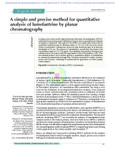
Fig. 1. Components
then be used to analyse a system, implement the system and as a basis for system change and maintenance. The paper provides a convincing argument that taking a language driven approach to software architecture (or software systems engineering in general) provides significant benefits in terms of clarity and in producing a shared development resource. This section provides a brief overview of the application described in [Vol08]. Figure 1 shows an overview of the airport application described in [Vol08]. The required system consists of three main components: an aircraft component produces real-time information about the status of flights as they proceed; a calculator component contains information about expected flight schedules and can compare flight updates with expectations to produce flight bulletins; a screen component manages a number of screens in order to display flight information to passengers. The model shown in figure 1 describes a basic architecture for the system in terms of components, their interfaces and the communication requirements between components. For example the flights component will inform the delay calculator using messages defined in the aircraft status interface. However, the model does not show how the architecture is intended to behave. For example, what style of messaging is to be used? Is time an issue? What patterns of behaviour (broadcast, point-to-point; shared-data etc) are to be used? In order to design the precise architecture required for the system it is necessary to express more detail than is usually found on a component architecture model. [Vol08] proposes that an effective way to achieve this description is to design a textual language for expressing architecture in order to precisely capture the required structure and behaviour. The paper describes a real-world occur-
component System { interface ScreenUpdate
{ expected(id:Id,time:Time); cancelled(id:Id); } interface AircraftStatus { position(id:Id,pos:Position); problem(id:Id,p:Problem); } struct Flight { id:Id; from:Airport; to:Airport; scheduled:Time; expected:Time; } component Calculator { provides aircraft:AircraftStatus; requires screen:ScreenUpdate; value flights:Flight[]; handler cHandler; } component Aircraft { requires calculator:AircraftStatus; handler aHandler; } component Screen { provides info:ScreenUpdate; handler sHandler; } instance screen:Screen instance aircraft:Aircraft instance calculator:Calculator connect calculator.screen to screen.info connect aircraft.calculator to calculator.aircraft
}
Fig. 2. An Architecture Description Language
rence of such a language design including the blind alleys and backtracking that occurs in practice. The resulting language consists of components, interfaces, ports, connections and data types. The definition in figure 2 shows how the system defined in figure 1 could be expressed using an architecture description language. The key features of the language are that components can be nested, each component defines ports via provides and requires declarations. A port is typed using an interface. Internal component state may be values (value) or instances of components (instance). Ports are connected using a connects declaration. The behaviour of a component is specified by a handler introduced by the keyword handler.
3
An Approach
The previous section described an architecture description language (ADL). This is an example of a DSL, but how was the DSL designed? Starting just from knowledge about the properties of components, how they are structured and how they behave, are there guidelines and steps that can be used to help develop the new language? This section proposes a framework for DSL design that can be used as a guide. The framework identifies key steps in the design life-cycle that are used to develop a DSL starting with a representation in a known language technology. It should be stressed that the framework and associated process is a method that can be applied rigorously or with a light-touch.
This section is structured as follows: section 3.1 describes how a language definition can be unrolled to produce scenarios; section 3.2 describes the framework and process that consists of performing unrolling in reverse.
3.1
Unrolling a Language
A technology independent language definition is often expressed as a relation using natural semantics that defines the relation using rules and axioms. This is an attractive way to define a DSL; however, initial discussions with a domain expert are likely to produce snippets of concrete examples rather than general computational rules. How can the gap between concrete examples (or scenarios) and general computational rules be bridged? The first step is to understand the relationship between the general and the particular and then to design a process that can move from the particular to the general. This section describes the relationship between DSL-specific computational rules, expressed as a natural semantics, and scenarios, expressed as ground programs. The relationship is defined by systematically unrolling the semantics through a number of stages, each stage adds more concrete implementation detail to the description until the language used to express the scenarios (in this case a simple functional language) is fixed (and known a priori by the language engineer). The next section then argues that an effective process for developing a DSL in terms of expert knowledge is to perform this unrolling process in reverse. Consider a simple language for performing expressions in terms of integers and strings. The language allows operators to be applied to values; there are a collection of builtin operators (such as integer addition) and a collection of composite operators, built from existing operators. A composite operator may be overloaded and will dispatch on the types of the arguments at run-time. The language has a simple type system that is statically applied before run-time. The first definition, shown below, defines a type checking relation. If Γ maps variables to types, Σx and x ˜ both denote indexed collections, [c]j indexes the element j from indexed collection c, e ranges over program expressions, s over strings, n over integers, v, w over variables. Γ ` e : Σ(˜ τ → τ) Γ ` e˜ : τ˜j [Σ(˜ τ → τ )]j = τ˜j → τj Γ ` e(˜ e) : τj
Γ ` s : str Γ ` n : int Γ ` v : Γ (v)
The operational semantics of the language is shown below. An overloaded operator is an indexed set of argument/expression pairs (w, ˜ e) where the indices are vectors of types. The meta-variable b ranges over builtin operators, x ranges over values (strings or integers), and Φ is an environment mapping variables to
values. Φ ` e ⇒ Σi∈T (w, ˜ e0 ) Φ ` e˜ ⇒ x ˜ Φ[w ˜j 7→ x ˜] ` e0j ⇒ x [Σi∈T (w, ˜ e0 )]j = (w ˜j , e0j ) type(˜ x) = w ˜j Φ ` e(˜ e) ⇒ x
Φ`e⇒b Φ ` e˜ ⇒ x ˜ Φ ` e(˜ e) ⇒ b(˜ x)
Φ`s⇒s Φ`n⇒n Φ ` v ⇒ Φ(v)
Unrolling a language definition will increase the coupling between the DSL and some implementation technology. The definition given above, has very little implementation coupling; the first step towards scenarios is to introduce some implementation in the form of an abstract machine for the language. There are some choices to be made here; for example, do we merge the type checking, and, what order do we impose on the evaluation of sub-expressions? The machine defined below introduces explicit ordering for evaluation (type checking produces a similar machine which is elided): (s, Φ, e(˜ e) : c, d) −→ (s, Φ, e : e˜ : @ : c, d) (˜ x : Σi∈T (w, ˜ e) : s, Φ, @ : c, d) −→ ([], Φ[w ˜j 7→ x ˜], [ej ], (s, Φ, c, d)) . . . as above (˜ x : b : c, Φ, @ : c, d) 7−→ (b(˜ x) : s, Φ, c, d) (s, Φ, x : c, d) 7−→ (x : s, Φ, c, d) (s, Φ, v : c, d) 7−→ (Φ(v) : s, Φ, c, d) A machine is functional and, although less abstract than a relational definition, is abstract with respect to the evaluation features of a particular implementation language. After all, that’s the point: a machine or relation uses a simple meta-language that involves pattern matching and a few auxiliary functions. Scenarios are written in a particular programming language and rely on the facilities provided by that language. The next unrolling step is to turn the machine into an interpreter in a chosen target language. A machine represents the complete execution state as data, including program, data values and interpretive machinery (such as stacks, tags, resumptions, environments). A machine can be implemented directly in any general purpose language, however some of the interpretive machinery of the machine can be absorbed into the execution features of the host language where appropriate. The following interpreter is written in a simple functional language (similar to Haskell). The abstract syntax of the language is represented using data constructors. Note that various features of the machine have been ’implemented’ using host language features. For example, recursion is used to implement the stack-based push and pop of the machine, and the environment of variable bindings has been implemented via a function called env. Various auxiliary functions are used in the interpreter, their definitions are intended to be obvious. Note also that type checking is merged into the interpreter via the isTypeOk operator, thereby merging in the type-checking machine (not defined above) with the execution machine. The rationale for this merge is that if all type-checking is performed as a pre-step, then all type-checking steps can be merged with all evaluation steps providing the original ordering is preserved.
eval env Apply(e,es) = let op = eval env e args = map (eval env) es in if typeOk op args then if isOverloadedFor op args then let f = indexFun op args in eval (extend env (names f) args) (body f) else if isBuiltin op then applyBuiltin op args else typeError eval env Str(s) = s eval env Int(n) = n eval env Var(s) = env s
The interpreter defined above is more concrete than the original relational language definition, however, it still represents general execution rules that are unlikely to be extracted via acquisition sessions with domain experts. Consider, running the interpreter, from some pre-defined point, by providing a program, or set of programs, together with some or all of the context(s). Instead of running the interpreter to conclusion, thereby producing a value, the interpreter can be executed to produce a new program S that is specialized to execute just the supplied program(s) in the supplied context(s). The result S has important axes of variability: generality S will be less general than the interpreter, but not necessarily specialized to a single program and context. For example, eval can be specialized with respect to all the type correct applications of built-in operators, or, with respect to 3-argument operators. In each case, knowledge of the structure and properties of the inputs will allow specialization of the interpreter and its auxiliary operators. evaluation S may delay evaluation of closed program expressions or may choose to evaluate them to produce a value. For example, if eval is supplied with an expression that adds two integer constants, then the evaluation of the recursive calls to eval can be unwound and left as sub-expressions. semantic S may be all program code, all run-time value (essentially the result), or a mixture of the two. For example, a program that works outside-in may perform definitions that are added to the run-time context, therefore S consists of the as-yet-unperformed program code and the context necessary to perform it. A collection of programs S that can be produced from the interpreter are called scenarios. Scenarios are programs that cover the spectrum from general evaluation rules (such as eval) to constant values. An interpreter, is classified by the set of all scenarios it denotes. The following is an example of several scenarios generated from a partial evaluation of eval. To set up the definition, we must supply eval with arguments, including values from the run-time context. To do this we will assume the existence of some run-time value constructors: overload that combines two
run-time occurrences of partial functions; guard that defines a partial function using a sequence of argument types and a closure; clo that builds a run-time occurrence of a function. To be clear about the context supplied to the call of eval it is written out below as a program where the context is the run-time occurrence produced at point ...: let mkGuard types op vals = if agree types vals then op vals else bot mkOverload f g vals = if f vals = bot then g vals else f vals in let addInts = mkGuard [int,int] fun(x,y) addInts(x,y) end addStrs = mkGuard [str,str] fun(x,y) addStrs(x,y) end in let add = mkOverload addInts addStrs in ...
Therefore the environment e passed to eval is a function that maps add to a run-time value o (for some basic environment e’): overload addi adds where addi = guard [str,str] (clo [x,y] e’ (mkBody addStrs)) adds = guard [int,int] (clo [x,y] e’ (mkBody addInts)) where mkBody name = Apply(Var(name),Var(x),Var(y))
Therefore eval e Apply(Var(add),(Int(1),Int(2)) produces the following scenario (after a few unrollings using knowledge of the supplied context): let op = o args = [1,2] in if typeOk op args then ...
Which is equivalent to: let x = 1 y = 2 in if typeOk o [x,y] then ...
Of course we now know that the overloaded operator o is type-correct. Therefore we can either unroll the definition of typeOk or elide it altogether. Since we know that the environment is extended with the values of x and y we can use knowledge of the structure of the environment supplied in the recursive call to eval to produce: let x = 1 y = 2 in addInts(x,y)
which is clearly 3. Although we arrived at the obvious answer, there were very many possible staging posts along the way. Each of these contained various ’memories’ of the execution machinery that was used to process the original general program structure and context. This section has shown how an implementation independent language definition can be unrolled to produce a characteristic set of scenarios with respect to a particular implementation language. A simple functional language has been used where program features include data constructors and functions, and run-time
features include closures. Any general purpose language is suitable, for example Java would include language features such as classes and methods and run-time features such as objects and exceptions. It has been noted that there are important unrolling stages: relational; functional (machine); interpreter; and, scenarios. It has also been noted that there are three main axes of variability when describing scenarios: generality; evaluation; semantic. The hypothesis of this paper is that scenarios are a natural by-product of a dialogue between a domain expert and a language engineer, and, they are a suitable point of departure for DSL definition; the next section describes such a process. 3.2
Abstracting a Language
The previous section has described a process of unrolling a language definition to produce scenarios. A DSL in development does not have a language definition; initial discussions between a domain expert and a language engineer produce scenarios expressed in a technology of the language engineer’s choice. Our hypothesis is that this is a suitable starting point for the definition of the DSL by rolling-up or abstracting the language definition – essentially reversing the process described in the previous section. Part of the abstracting can be supported by tools, although that is outside the scope of this paper. The process is shown in figure 3. It consists of a scenario gathering phase where typical system executions are described using a well understood language. Once the scenarios are believed to be complete then an interpreter is written that would give rise, via partial execution, to all the individual scenarios. Once the interpreter is complete, it may be necessary to transform it in order to identify different phases; for example, static phases that perform checking and dynamic phases that expect correct programs. An interpreter uses a mixture of explicit evaluation mechanisms and mechanisms ’inherited’ from Fig. 3. Language Definithe underlying implementation language. It has tion Process been observed many times before where, in defining the semantics of Pascal using a Pascal interpreter, for example, the semantics of parameter passing is defined using Pascal parameter passing. The only way out of this dependency, is to ’lift’ the interpreter (forcing out the hidden interpretive dependencies in the process) into an abstract machine.
Finally, the machine, although abstract, includes execution machinery that can often usefully be elided (stacks, resumptions etc). Therefore, the machine can be abstracted to a relational definition (in the style of [Plo04]) that ’forgets’ certain execution irrelevancies.
4
Developing Scenarios
The first phase in the proposed language definition process is to construct sets of scenarios. Each scenario should be expressed using a notation that is suitable for analysis and transformation. This paper uses a simple functional notation. Scenario construction is a dialogue between the developer and the domain expert. Particular execution cases are examined and gradually expressed as an executable program. Scenario construction can stop when sufficient cases have been developed in order to be complete with respect to the required system. Each scenario can be developed incrementally by analysing different phases of execution within the scenario. Often, a program will have several execution phases that are naturally sequential and this can help when defining scenarios, particularly if the phases coincide with the structure of the information. For example, many programs will have at least a definition and an execution phase, where the definition occurs before the execution. This paper uses the proposed approach to develop a language semantics for the ADL described in section 2. It is not possible, given space restrictions, to be complete with respect to the scenarios; to do so would involve constructing programs where the number of components vary, where the number of ports and connections vary, and where the depth of component nesting varies. We consider a single scenario consisting of four components as shown in figure 1 (the fourth component is the containing system). Imagine that, through discussions with the domain expert, the following lifecycle phases are identified for the scenarios: Definition the components are defined. Checking may occur at this stage. Instantiation component definitions are used to create component instances each of which has a unique identity and state. Messaging the system processes information by sending messages between components. The rest of this section develops a single scenario, step-by-step, by analysing each of these phases in turn. The presentation aims to represent the steps performed by a language engineer, the questions that arise and the discoveries that are made. 4.1
Definition Phase
Components are the main structural feature of the language and follow a principle of recursive decomposition. Evaluation of a component definition produces a component that can then be instantiated many times. Components view each
other as black-boxes; this will affect how component definitions are scoped over each other. Interfaces are used to construct messages and to type ports (and therefore to check whether a connection is legal). Interfaces are defined in a component and are available to all sub-components. Structures are used to type component states and message components; they are also available to all sub-components. Components can be represented as functions of 0 arguments; instantiation occurs when the function is applied. A structure definition, such as Flight is a bundle of constructor and accessor functions. Interfaces are records associating message names with type signatures (also records). The entire system is a function that, when instantiated, defines the sub-components and instantiates them: let System() = ... let Flight = (mkFlight,flightId,...) ScreenUpdate = [ expected->[ id->Id, time->Time], ...] AicraftStatus = ... in let Calc() = ... Aircraft() = ... Screen() = ... in let screen = Screen() calc = Calc() aircraft = Aircraft() in ... return system ...
The structure of a component definition has started to take shape. Notice how the structure can be recursively applied to the sub-components. 4.2
Instantiation Phase
Each component definition may give rise to more than one instance with its own unique identity. In this case, identity arises because each component instance may have a different state that changes over time. How should the identity of a component be represented? A system will process messages that are sent from and to ports that are connected between components. In order for ports to be associated with appropriate messages, they will have a unique id. Component instantiation must achieve the following: create a new component instance; create new ports with unique identifiers usingmkPort to allocate a unique id for each port; instantiate any sub-components; create any state owned by the component instance. Component definitions specify port connectivity. Does this occur at component instantiation time? This depends on how the message delivery service is to be represented. If messages contain port identifiers then connectivity between output and input ports can be achieved by replacing an output port identifier with the corresponding input port identifiers. Therefore connectivity can be processed at execution time rather than instantiation time. Since we are not interested in efficiency, type checking the connections can also be deferred to execution time. Component instances need to process messages that are appropriate to them or their sub-components. A suitable representation for a component instance is
a function of two arguments: the messages and the current time. The parent component is responsible for supplying child components with appropriate messages. This can only happen if the parent is aware of the ports owned by the child. Therefore, the ports owned by a component must be available as part of its representation. The following shows how the calculator component is defined: let Calc() = let screen = mkPort(ScreenUpdate) aircraft = mkPort(AircraftStatus) flights = [] in let execCalc(M,time) = ... in (execCalc,screen,aircraft)
The calculator instance consists of a message handler and a pair of ports. This allows the parent to apply the appropriate messages (elt t i indexes the ith element of tuple t: let System() = let ... c = Calc() then execSystem(M,time) = let ... = (elt c 0)(calcFilter(c,M),time) in ... in execSystem
Notice that the parent knows the structure of the sub-components, by indexing the 0th element of component instance c, and in the definition of the message filter (the backslash operator restricts a set of messages to those with the supplied id): calcFilter((_,_,i),M) = M\portId(i)
In the case of the system component, there are no ports so the instance is just a message processing function execSystem; this is an example where a scenario is specific to the example, when we abstract an interpreter we will need to find a general representation whose unrolling is consistent with the different representations shown here. 4.3
Messaging Phase
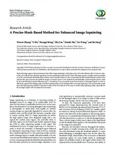
Handlers are arbitrary functions that process messages and may change the state of a component instance. A standard way to model such a state change is for the handler to take the current state of the instance as input and produce a new state as output. Therefore, language execution is a sequence of state transitions that deconstructs the component tree, supplies messages to the components, produces output messages and reconstructs the component tree ready for the next iteration. Messages produced as output from the previous iteration are supplied as input to the next. The following shows the execution machinery for the calculator component; note the use of cHandler: let Calc() = let screen = mkPort(ScreenUpdate) aircraft = mkPort(AircraftStatus)
Fig. 4. execCalc
flights = [] in letrec execCalc(flights)(M,time) = let (flights’,O) = cHandler(M,time,flights) in ((execCalc(flights’),screen,aircraft),O) in (execCalc(flights),screen,aircraft)
The delay calculator behaviour is handled by a function execCalc. Figure 4 shows the behaviour of execCalc where unfilled boxes are functions and the filled boxes are value locations. The current value of flights is supplied to execCalc which returns a function that contains the current value of flights. The returned function processes messages M and the current time by supplying them to the handler which in turn returns a new value of flights and some output messages. The new value of flights is the new component state and is fed back to the execCalc function. The separation between supplying the state (flights) and the messages (M) allows the system to implement components with state change. Ports are connected in order to route messages through a component architecture. Messages are produced by handlers and contain the identifier of the port that is to bear the message. Connection can be implemented by replacing the identifier of an output port with the id of a connected input port. Suppose that the delay calculator is the only component with state (others would follow the same pattern): let System() = ... letrec execSystem(calc)(M,time) = let O = (elt screen 0)(screenFilter(screen,M),time) (calc’,O’) = (1st calc)(calcFilter(calc,M),time) O’’ = aircraft(time) Out = connectCtoS(calc,screen,O+O’+O’’) in (execSystem(calc’),connectAtoC(aircraft,calc,Out)) in execSystem(calc)
System() = let Flight = (mkFlight,flightId,...) ScreenUpdate = [expected->[id->Id,time->Time],...] AircraftStatus = [position->...,problem->...] then Calc() = letrec aircraft = mkPort(aircraftStatus) screen = mkPort(screenUpdate) flights = [] execCalc(flights)(M,time) = let (flights’,O) = cHandler(M,time,self) in (execCalc(flights’),aircraft,screen,O) in (execCalc(flights),aircraft,screen) Aircraft() = let calc = mkPort(AicraftStatus) execAircraft(M,time) = aHandler(M,time) in (execAir,calc) Screen() = let info = mkport(ScreenUpdate) execScreen(M,time) = sHandler(M,time) in (execScreen,info) screen = Screen() aircraft = Aircraft() calc = Calc() in letrec execSystem(calc)(M,time) = let O1 = (elt screen 0)(screenFilter(screen,M),time) (calc’,O2) = (1st calc)(calcFilter(calc,M),time) O3 = aircraft(time) then Out = connectCtoS(calc,screen,O1+O2+O3) in (execSystem(calc’),connectAtoC(aircraft,calc,Out)) in execSystem(calc)
Fig. 5. Ground Scenario Program
The connection operations are specific to each connection and replace the port identifiers in the output messages (the [ / ] operator substitutes identifiers in sets of ports): connectCtoS((_,i),(_,o,_),M) = M[portId(i)/portId(o)] connectAtoC((_,_,i),(,o),M) = M[portId(i)/portsId(o)]
4.4
Complete Scenario
The complete system definition is shown in figure 5 and is executed by run: letrec run(system,M,time) = let (system’,O) = system(M,time) in run(system’,O,time+1)
As it stands, the program is too specific and relies on knowledge of the application. For example there are different representations for components depending on whether the component has state and/or ports. In addition, the program relies on knowledge of the names used in the example scenario and references in them in concrete ways (i.e. in let-binding).
5
Abstracting an Interpreter
Interpreter abstraction starts with the scenario program shown in figure 5 and transforms it, step-by-step, into a program that takes a data representation of the program. The interpreter for component definitions will be called cmp and the first step is to abstract over names by introducing types and interface tables t and i containing definitions. Wherever the original program referenced a particular type or interface name, this is replaced with a reference using the appropriate table: let cmp(name,t,i)() = let Calc = ... Aircraft = ... Screen = ... ... cHandler(M,...,i,t)
Sub-components are performed next. Ideally, the interpretive mechanism that gives rise to the parent component should apply to the child components. Recall that the local type and interface definitions of the parent are scoped over the child. The parent type and interface definitions can be passed down to the child using interpreter arguments t’ and i’ as follows (where / is the fold operator and + concatenates records): letrec cmp(n,t,i,ds) t’ i’ = n->component where component() = let cs = /(+)[](\c. cmp c(t+t’)(i+i’))ds ... in ...
Components are represented as functions that are awaiting 0 arguments. When the arguments are supplied, a new instance is returned. A component is therefore represented as a closure. The values required when the component is instantiated are closed into the function. The component definition interpreter is completed by lifting all the values out of the closures and finding a common representation (this is like the defunctionalization of Reynolds [Dan06]): letrec cmp(n,t,i,ds,is,ps,vs,xs,h) t’ i’ = n -> component where component = (t+t’,i+i’,c,ps,is,vs,xs,h) where c = /(+)[](\c. cmp c(t+t’)(i+i’))ds
The representation and definition of cmp is correct providing that there is a definition that instantiates components and subsequently processes messages correctly. This is designed by analysing the requirements of the components from the scenario program and abstracting an interpreter new. The argument to new is a package of information including port definitions, instance definitions, value definitions, connections and a handler. Consider the following port definitions for the delay calculator (s and t are tags for supplied and required ports): psCalc = [ "aircraft"->s("aircraftStatus"), "screen"->r("screenUpdate") ] vsCalc = [ "flights"->["flight"] ]
This gives rise to the following requirement for the instantiator: new(t,i,c,psCalc,[],vsCalc,[],cHandler) = letrec aircraft = mkPort(s,i("aircraftStatus")) screen = mkPort(r,i("screenUpdate")) flights = [] ... in ...
Removing the names from the interpreter forces a representation for ports and state: new(t,i,c,ps,[],vs,[],cHandler) = letrec ports = /(+)[](\n->(pt,in).n->mkPort(pt,i(in)))ps state = /(+)[](\n->tn.n->mkStruct(t(tn))vs ... in ...
Having reified the names of the ports and the state, this leads us to a fairly straightforward representation for component instances: new(t,i,c,ps,is,vs,xs,h) = letrec ports = ... state = ... then execObj(M,time,self) = let (state’,O) = h(M,time,self) in ((execObj,state’,ports),O) in (execObj,state,ports)
This takes care of all the aircraft components. However, the System component contains two extra features: instantiated sub-components and port connections. The sub-components must be sent the appropriate messages; in response they produce output messages and possibly change state: new(t,i,c,ps,is,vs,xs,h) = letrec ports = ... state = ... objs = /(+)[](\n->cn.n->new(c(cn)))is then execObj(M,time,self) = let (state’,O) = h(M,time,self) (objs’,O’) = /(+)[](\n->o.n->(send o M))objs in ((execObj,state’,objs’,ports),O+O’) in (execObj,state,objs,ports)
Finally, the output messages must accommodate the connections. This is achieved by renaming the port identifiers involved in the connection: new(t,i,c,ps,is,vs,xs,h) = letrec ... then newObj(M,time,self) = let ... (objs’,O’) = ... then O’’ = connect xs objs’ O’ in ((newObj,state’,objs’,ports),O+O’’) in (newObj,state,objs,ports)
Def Cmp BodyDef StateDef PortDef ValueDef Type Interface PortType ValType Connect Handler Objects Port State Value Message
Cd =S × T S × I S × [Cd ] × Bd C =T S × I S × [C] × Bd Bd =Zd × Pd × Vd × [X] × H Zd =S s Pd =(Pt × S)S Vd =TvS T =T S | S I =(T S )S Pt =• |⊂ Tv =S | [S] X =S × S × S × S H =[M ] × T ime × O → Z × [M ] O =T × I × P S × S × OS × [X] × H P =Pt × N × I Z =V S V =N × S × B × V S M =Int × S × [V ]
Fig. 6. Component Interpreter Types
The instantiation is now completely abstract in terms of the input program. However, a component instance is represented in terms of a closure. The representation can be abstracted into the interpretive mechanism producing the three phase interpreter shown in figure 7 with associated type definitions as defined in figure 6 that use the following conventions: [X] denotes lists of elements of type X ; X S denotes environments which are sequences of maplets from elements of type S to elements to type X; N, S and B denote integers, strings and booleans respectively.
6
Language Specification
The next step in the abstraction process is to translate the interpreter into a machine and then into a natural semantics. Given the space limitations we jump straight to the natural semantics; a machine can be recovered by imposing an order on evaluation of sub-expressions via stacks and resumptions. The relation i, ι ` d ⇒p p, ι0 processes port definitions d to produce ports p; it is defined in figure 8(a). The integer ι is used to allocate unique identifiers to ports and the environment i provides interface information for the port definition. The interpreter defined in figure 7 uses separate phases for definition and instantiation. This choice arose from an early assumption about the program life-cycle. However, analysis of the interpreter shows that the processing of the two phases is isomorphic and could be coalesced without undue complication. The relation t, i, ι ` d ⇒n c, ι0 defines instantiation of a component definition d to produce a component c; it is defined in figure 8(b) and uses a function
cmp : Def -> Env(Str,Type) -> Env(Str,Interface) -> Env(Str,Cmp) letrec cmp(n,t,i,ds,is,ps,vs,xs,h) t’ i’ = n -> component where component = (t+t’,i+i’,c,ps,is,vs,xs,h) where c = /(+)[](\d.cmp d(t+t’)(i+i’))ds new:Cmp -> Object letrec new(t,i,c,ps,is,vs,xs,h) = let ports = /(+)[](n->mapsto(pt,in).n->mkport(pt,i(in)))ps state = /(+)[](n->tn.n->mkStruct(t(tn))vs objs = /(+)[](n->cs.n->new(c(cn)))is then in (t,i,ports,state,objs,xs,h) send:([Message],Time,Object) -> (Object,[Message]) letrec send(M,time,(t,i,p,s,o,xs,h)) = let M’ = filter M (t,i,p,s,o,cs,h) then (s’,O1) = h(M’,time,(t,i,p,s,o,xs,h)) (o’,O2) = /(+)[](\n->o.n->send(M’,time,o))o then O3 = connect xs o’ (O1 + O2) in ((t,i,p,s’,o’,xs,h),O3) connect:([X],Env(Str,Object),[Message])->[Message] let connect [] o O = O let connect (n1,n2,n3,n4):xs o O = let (_,_,pins,_,_,_,_) = lookup(o,n1) (_,_,pouts,_,_,_,_) = lookup(o,n3) then pin = lookup(pins,n2) pout = lookup(pouts,n4) in connect xs o O[portId(pin)/portId(pout)] filter:([Message],Object)->[Message] letrec filter M (_,_,p,_,o,_,_) = (M\(/(+)[](\n->p.portid(p))p)) + (/(+)[](\n->o.filter M o)o)
Fig. 7. Interpreter
new (not shown) that creates local state from value declarations by creating an environment mapping state names to initial values. Message passing is defined by the relation M, τ ` C ⇒s C 0 , O where M is a collection of (input) messages, τ is the current time, C is a collection of objects (in a pre-state), C 0 is a collection of objects (in a post-state) after the messages have been processed, and O is a set of (output) messages. The relation is defined in figure 8(c). The function filter extracts messages from a supplied set M that target an object and any of its sub-objects. The handler is supplied with a set of messages and an object-state; the handler returns a new object state and a set of output messages. The function connect translates any port ids in output messages to the appropriate input port ids so that they target the correct objects in the next evaluation cycle.
⇒ p : I S × N × Pd × P × N i, ι ` [] ⇒p [], ι i, ι ` x ⇒p y, ι0 i, ι ` n 7→ x ⇒p n 7→ y, ι0 i, ι ` e1 ⇒p e3 , ι1 i, ι1 ` e2 ⇒p e4 , ι0 i, ι ` e1 + e2 ⇒p e3 + e4 , ι0
⇒n : T S × I S × N × Def × O × N t + t0 , i + i0 , ι ` p ⇒p φ, ι0 t + t0 , i + i0 , ι0 ` z ⇒n κ, ι00 σ = new(x, t + t0 ) 0 0 t , i , ι ` (t, i, c, p, z, v, x, h) ⇒n (φ, κ, σ, x, h), ι00
i, ι ` (•, n) ⇒p (•, ι, i(n)), ι + 1
(b) Instantiation
i, ι ` (⊂, n) ⇒p (⊂, ι, i(n)), ι + 1 (a) Port Definition ⇒s : [M ] × T ime × O × O × [M ] M, τ ` [] ⇒s [], [] M, τ ` e1 ⇒s e3 , O1 M, τ ` e2 ⇒s e4 , O2 M, τ ` e1 + e2 ⇒s e3 + e4 , O1 ∪ O2 M, τ ` x ⇒s y, O M, τ ` n 7→ x ⇒s n 7→ y, O f ilter(M, (φ, κ, σ, x, h)), τ ` κ ⇒s κ0 , O1 (σ 0 , O2 ) = h(M, τ, (φ, κ, σ, x, h)) O0 = connect(x, κ, O1 ∪ O2 ) N, τ ` (φ, κ, σ, x, h) ⇒s (φ, κ0 , σ 0 , x, h), O0 (c) Message Massing Fig. 8. Language Definition
7
Review and Related Work
Domain specific languages have been proposed as being a useful tool in the development of a system both at the design and implementation stages. The literature provides guidance on how to implement and architect a DSL, however although it is pointed out in the keynote [vdB08] that there is a requirement for DSL methods there is little reported work on a method for the development of a DSL. This paper has proposed a method for the precise definition of a DSL and provided an example taken from a reported industry case study. Visser proposes a similar approach in [Vis07] which consists of DSL design patterns: finding programming patterns, designing a core language, and building
syntactic abstractions. This is essentially the same approach that is proposed in this paper except that Visser proposes to detect syntactic programming patterns in an existing language like Java; this leads to templates with holes. This paper has proposed an approach where patterns are not based on the target language and may consist of both syntax and semantic data items, i.e. partially evaluated (idealised) programs. Scenarios allow different aspects of a language to be represented and analysed, see [Cle03] for a different approach with similar aims. The relationship between executable meta-models and requirements engineering is described in [BNT07], and the relationship between grammars and meta-models is described in [JBK06]. Model based technologies such as these are suitable as a basis for the approach described in this paper. Cook [CDF+ 08] describes an approach where DSLs are defined in terms of language interpreters rather than in terms of language translations. This is related to the approach described here in the sense that the semantics of the DSL is essentially given in terms of an interpreter. However, this work is addresses a systematic approach to defining the interpreter whereas Cook at al. are interested in making interpreters efficient through the use of partial evaluation. A process for engineering languages based on grammars is described in [AV08], and a product-line DSL is developed using technologies provided by OpenArchitectureWare [SLFG08]. The approach described in this paper is different in that it uses abstract syntax to describe and analyse execution descriptions. A complete DSL will include a concrete syntax description, where syntax directed approaches would complement the approach described here. The analysis of many instance models in order to infer a meta-model via a grammar is described in [JMGB08]; the scenario-based approach described in this paper is related in the sense that both approaches work from the particular to the general, although [JMGB08] focuses on static data structure rather than whole programs.
References [ACH+ 08] Eric Allen, David Chase, Joe Hallett, Victor Luchangco, JanWillem Maessen, Sukyoung Ryu, Guy L. Steele Jr., and Sam TobinHochstadt. The fortress language specication. 2008. Available at http://projectfortress.sun.com. [AV08] Tiago L. Alves and Joost Visser. A case study in grammar engineering. In SLE, pages 285–304, 2008. [BNT07] Benoit Baudry, Clementine Nebut, and Yves Le Traon. Model-driven engineering for requirements analysis. In EDOC ’07: Proceedings of the 11th IEEE International Enterprise Distributed Object Computing Conference, page 459, Washington, DC, USA, 2007. IEEE Computer Society. [BS02] Claus Brabrand and Michael I. Schwartzbach. Growing languages with metamorphic syntax macros. In PEPM ’02: Proceedings of the 2002 ACM SIGPLAN workshop on Partial evaluation and semantics-based program manipulation, pages 31–40, New York, NY, USA, 2002. ACM. [CDF+ 08] W. Cook, B. Delaware, T. Finsterbusch, A. Ibrahim, and B. Wiedermann. Strategic programming by model interpretation and par-
tial evaluation. 2008. http://www.cs.utexas.edu/~wcook/Drafts/ 2008/StrategicProg08cook.pdf. [Cle03] Thomas Cleenewerck. Component-based dsl development. In GPCE ’03: Proceedings of the 2nd international conference on Generative programming and component engineering, pages 245–264, New York, NY, USA, 2003. Springer-Verlag New York, Inc. [Dan06] Olivier Danvy. Refunctionalization at work. In Mathematics of Program Construction, 8th International Conference, MPC 2006, Kuressaare, Estonia, July 3-5, 2006, page 4, 2006. [JBK06] Fr´ed´eric Jouault, Jean B´ezivin, and Ivan Kurtev. Tcs:: a dsl for the specification of textual concrete syntaxes in model engineering. In GPCE ’06: Proceedings of the 5th international conference on Generative programming and component engineering, pages 249–254, New York, NY, USA, 2006. ACM. [JMGB08] Faizan Javed, Marjan Mernik, Jeff Gray, and Barrett R. Bryant. Mars: A metamodel recovery system using grammar inference. Inf. Softw. Technol., 50(9-10):948–968, 2008. [LMM04] Julia L. Lawall, Anne-Fran¸coise Le Meur, and Gilles Muller. On designing a target-independent dsl for safe os process-scheduling components. In GPCE, pages 436–455, 2004. [MHS05] Marjan Mernik, Jan Heering, and Anthony M. Sloane. When and how to develop domain-specific languages. ACM Comput. Surv., 37(4):316–344, 2005. [Plo04] Gordon D. Plotkin. A structural approach to operational semantics. J. Log. Algebr. Program., 60-61:17–139, 2004. [SLFG08] Pablo S´ anchez, Neil Loughran, Lidia Fuentes, and Alessandro Garcia. Engineering languages for specifying product-derivation processes in software product lines. In SLE, pages 188–207, 2008. [Spi01] Diomidis Spinellis. Notable design patterns for domain-specific languages. Journal of Systems and Software, 56(1):91–99, 2001. [Ste98] Guy L. Steele, Jr. Growing a language. In OOPSLA ’98 Addendum: Addendum to the 1998 proceedings of the conference on Object-oriented programming, systems, languages, and applications (Addendum), New York, NY, USA, 1998. ACM. [vdB08] M. G. J. van den Brand. Model-driven engineering meets generic language technology. In SLE, pages 8–15, 2008. [vDK01] Arie van Deursen and Paul Klint. Domain-specific language design requires feature descriptions. Journal of Computing and Information Technology, 10:2002, 2001. [Vis07] Eelco Visser. Webdsl: A case study in domain-specific language engineering. In GTTSE, pages 291–373, 2007. [Vol08] Markus Volter. Architecture as language: A story. InfoQ, 2008. http://www.infoq.com/articles/architecture-as-language-a-story. [War94] Martin P. Ward. Language-oriented programming. Software - Concepts and Tools, 15(4):147–161, 1994. [Wil01] David S. Wile. Supporting the dsl spectrum. Journal of Computing and Information Technology, 4:263–287, 2001.