Abstract: This paper presents the pre-processing scheme used for a vision system for a self-navigating mobile robot which relies on straight line detection using ...
IOSR Journal of Computer Engineering (IOSR-JCE) e-ISSN: 2278-0661,p-ISSN: 2278-8727, Volume 18, Issue 1, Ver. I (Jan – Feb. 2016), PP 09-15 www.iosrjournals.org
A Preprocessing Scheme for Line Detection with the Hough Transform for Mobile Robot Self-Navigation Gideon Kanji Damaryam1, Haruna Abdu2 1 2
(Department of Computer Science, Federal University, Lokoja, Nigeria) (Department of Computer Science, Federal University, Lokoja, Nigeria)
Abstract: This paper presents the pre-processing scheme used for a vision system for a self-navigating mobile robot which relies on straight line detection using the Straight Line Hough transform. The straight line Hough transform is an Image Processing technique for detection of straight lines in an image by transforming points in the image to another image in a way that accumulates evidence that the points from the original image are constituents of a straight line type feature from the original image. The pre-processing presented includes image re-sizing, conversion to gray scale, edge detection using the Sobel edge-detection filters, and edge thinning with a newly developed method that is a slight modification of an existing method. The newly developed method has been found to yield thinned images more suitable for later stages of this work than other thinning methods. Output from the pre-processing scheme presented is used as input for the remainder of the vision-based selfnavigation system. Keywords: Edge-detection, Hough transform, Image Processing, Machine vision, Pre-processing
I.
Introduction
This paper describes an image pre-processing scheme, which t ransforms an image captured by a camera mounted on a mobile robot, into a representative binary image optimized for straight-line detection using the Hough transform. Straight lines are detected as part of a vision system for a mob ile robot, wh ich works by detecting and interpreting lines and end-point of lines to find navigationally important features .Detection of lines is detailed in [1] and determination of end-points of lines is detailed in [2]. The vision system is part of a self-navigation system intended for use by a small mobile robot within a rectilinear indoor environment such as a University facu lty building. The full system is described in [3]. Hough transforms are used for detection of features such as lines, curves and simple shapes within images. They work by transforming potential parts of a target feature in a given image topoints in a new image while accu mulat ing measures of the likelihood that points in the new image aredue to features of the required type from the orig inal image. When the transformat ion is complete, points in the new image can then be subjected to a predefined threshold so that points that are very likely to be due to the required kind of feature can be selected and the original features identified by reversing the transformat ion process. The Hough transform used depends on the feature to be detected. As the work that is the basis of this paper is concerned with the detection of straight lines, it prepares images for the transform called the straight line Hough transform, wh ich transforms points, being potential co mponents of lines, in the orig inal image to curves in a new image. The number of curves that intersect at a particular point in the new image is a measure o f the likelihood that the points from the original image whose transform curves intersect at the intersecting points in the new image, were points forming a straight line in the original image. The line is defined by values of the transform parameters which can be read off the axes of the new image. Th is way, lines in the orig inal image can be detected. For brevity, in this work, the straight line Hough transform is simply referred to as the Hough transform, as is common ly done. Further information about the Hough transform is available in several publications including [4] and[3]. In the context of the Hough transform, the processing required to transform an image captured by a camera (a raw image), to an image optimized for application of the Hough transform is referred to as preprocessing. The pre-processing tasks presented in this paper include resizing of the captured image, edgedetection and edge-thinning.Image capture is first discussed also, although it is not part of pre-processing in a very strict sense.
II.
Capture, Resizing and Conversion to Gray Scale
2.1 Capture-Process-Navigate Cycle To achieve vision-based navigation, it is necessary to capture, and process an image, and then effect navigation on the basis of the result of the processing. This cycle is repeated until a predefined navigation programme is completely executed, or the entire navigation process is otherwise terminated. DOI: 10.9790/0661-18110915
www.iosrjournals.org
9 | Page
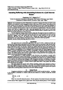
A Preprocessing Scheme for Line Detection with the Hough Transform for Mobile Robot… 2.2 Capture In this work, images were captured using a single forward-facing camera. It was ensured that there was sufficient light to clearly identify separate features in the images such as walls, floors a nd doors. The base of the camera was set up parallel to the floor. 2.3 Resizing A standard image size was chosen to give a good compromise between usefulness of output and processing time. The reduced image size chosen was 128 x 96 pixels. When this size of image is fully processed, fairly fine details such as the two edges of a door on the side of a corridor can be extracted, yet the time fo r processing the image is not prohibitive. Other image sizes were tried. These included 32x32 pixels and 64x48 pixels. In both cases, the level of detail availab le when the image is fully processed is limited and means that higher level post-processes to interpret the results do not have adequate input. A feature such as a door that is noticeable to a human observer in an image can be reduced to a single line if the image is reduced to a 32 x 32 size, and so the door cannot be picked up as a door by the post-processing for detecting doors, for examp le. Fig. 1 shows the various types of results for a typical image. Fig. 1a is the original image magnified by 2.67, figure 1b is the 32 x 32 thinned version magnified by 8, figure 1c is the 64 x 64 version magnified by 4 and figure 1d is the 128 x 96 version again magnified by 2.67. The door circled in figure 1a has no chance of being picked up as a door in the 32 x 32 thinned image because it almost doesn’t appear, and in the 64 x 64 thinned image because it appears as a single line. Also, although a square aspect ratio was considered, a 4:3 aspect ratio was selected as the ca meras used all captured in 4:3 ratio and changing the ratio led to unnecessary loss of information fro m the sides as shownin Fig. 1 below.
Figure 1 Effects of various image sizes (Top left) Orig inal image magnified by 2.67(Top right) 32 x 32 thinned image magn ified 8 times(Bottom left)64 x 64 thinned image magnified 4 times(Bottom right)128 x 96 thinned image magnified by 2.67 Depending on the target features, the algorithms used for detecting them, and the importance of timeliness for specific applications, other image resolutions can be used. [5] Used a 30 x 32 sized grey-scale DOI: 10.9790/0661-18110915
www.iosrjournals.org
10 | Page
A Preprocessing Scheme for Line Detection with the Hough Transform for Mobile Robot… image as input to a neural network fo r the purpose of navigating a robot to avoid moving obstacles and turning into junctions. [6]Reduced512 x 480 sized images to 64 x 60 sized images in their Corridor Follower module and then usedthoseas input for the Hough transform. They then used the resulting Hough space as input to a neural network.They report that the reduction in size has no noticeable effects on the performance of the module. [7]resizedcaptured images of size512 x 512 to a 256 x 256 size – a higher resolution than the images in the current work - and usedthem to locate a docking station using an algorithm that requires up to 5 runs of the Hough transform. They report very h igh processing times (up to 10 minutes) however.
2.4 Intensity Determination The camera used for this work captures coloured images. These are stored as image objects that have informat ion about the levels of primary colors (red, blue and green) at every point of the image. For edgedetection to commence, it is necessary to determine the intensity at each point. This is done by extracting the level of each of the three colours and determin ing the average at each point.
2.5 Image Point Indexing Points in images are labeled with identificat ion codes as illustrated in Fig. 2. The point at the top-left position is labeled 0. Subsequent points going right are labeled with consecutive numbers until the end of the row. The labeling is continued on the next row fro m the left.
Figure 2: Image points indexing
III.
Edge Detection
Edge-detection is the first pre-processing step implemented after an image of the right size has been obtained. It yields an edge-image by plotting lines connecting points where there are significant changes in pixel intensity, and which can therefore be taken as indications of edges of features in the image[8]. An edge image, ideally, contains lines that outline features in the original image. With the intensities in the grey-scale image determined as discussed in 2.4 Intensity Determination, a filter is applied across the image, wh ich works out for each point in the image, the possibility that the point is an edge. A threshold, selection of which is a task in itself, is then applied to select points with high possibilities of being edge points. The Sobel edge-detection filters were chosen for this work. Other edge-detection filters and techniques exist. One examp le is using the Laplacian edge-detection filters which havealsobeen reported to be accurate for detecting edges which are very gradual [8]. The Sobel filters were chosen for this work because not only do they provide a measure of magnitude for gradients of edges which were found to be good enough for images of the type used in this work, they also provide angles for the gradients that are used in some thinning algorith ms, including the one used in this work. Thinn ing in this work is discussed shortly in IV. Edge Thinning. A fuller discussion on the Sobel filters is available in [8], as well as several other resources. The Sobel filters are two 3 x 3 matrices, M ver and M hor . These are applied across images. Mveris designed to find vertical edges and Mhor is designed to find horizontal edges. M ver is defined as:
DOI: 10.9790/0661-18110915
www.iosrjournals.org
11 | Page
A Preprocessing Scheme for Line Detection with the Hough Transform for Mobile Robot…
M
and M
hor
ver
1 2 1
0
1 0 1
2
0 0
1 2 1
.
.
.
.
.
(1)
.
.
.
.
.
(2)
defined as:
M
hor
1 0 1
0 2
The filters yield a measure of the possibility that there is a vertical and a horizontal edge, respectively, at a given point. These measures are called grad ient magnitudes. The two gradient magnitudes, gm ver and gm
hor
, are obtained by convolution of the respective filters with the image I : gm
ver
M
gm
hor
M
ver
*I
hor
*I
.
.
.
.
.
(3)
.
.
.
.
.
(4)
.
(5)
The two are then summed to give an overall grad ient magnitude, 𝑔𝑚 for the point: gm gm
ver
gm
hor
.
.
.
.
The Sobel filters also provide an estimate of the angle, of the gradient. This is simp ly the arc tangent of the horizontal g radient magnitude divided by the vertical gradient magnitude:
tan
1
gm gm
hor ver
.
.
.
.
.
(6)
3.1 Edge Threshol d determination Once gradient magnitudes have been determined, the next stage in edge -detection is deciding from the gradient magnitudes, which points are edge points and which ones are not. This involves application of a threshold. This work has developed a scheme where, rather than assign a fixed threshold for determining edges, a target is provided of the number of edge points required. The following algorithmis then used to work out what threshold will result in getting a number of edges equal to, or a little more than that specified: 1.
Determine maximu m gradient magnitude, M , fro m the array of gradient magnitudes GM
2. 3. 4.
Determine minimu m gradient magnitude, m , fro m the array of gradient magnitudes GM Determine range of gradient magnitudes, R , using R M m 1 Determine target number of non-edge points, N ' , as the difference between total number of points, N ,
5.
and target number of peaks, T ' , i.e. N ' N T ' Determine the number of elements of GM having value a for each a where m
≤ a M
and store
each as G a 6.
Initialize a counting variable i to M , and set S i , the𝑀𝑡ℎ cu mulative su m, to G m
7. 8.
Reduce i by 1 Add previous cumulative g roup count to current group count to get current cumu lative group count, i.e.,𝑆𝑖 = 𝑆𝑖+1 + 𝐺𝑖 If current cumu lative group sum, S i , is equal to or greater than target number of peaks,𝑁, do 10, else go
9.
back to 7 Set threshold to the current count and stop The gradient magnitudes determined by application of the Sobel edge -detection filters, provides input for this algorithm. 10.
DOI: 10.9790/0661-18110915
www.iosrjournals.org
12 | Page
A Preprocessing Scheme for Line Detection with the Hough Transform for Mobile Robot… 3.2 Sample Edge Detection Result Sample results are shown in Fig. 3. Fig. 3a is a typical image, and Fig. 3b is the same image after it has been converted to grey-scale and Sobel edge detection has been applied to it.
Figure 3a: Samp le Image
Figure 3 b: Sample Image after Sobel Edge Detection
Figure 3: Sample Sobel edge detection results IV.
Edge Thinning
Edge-detection often yields edges several pixels thick. This can make further processing of the image unnecessarily processing time and memory consuming, and “distracts” feature detection processes from important but salient features of the image. The objective of edge thinning is t o reduce edges to unit thickness without losing any information about the connectedness of edges or introducing any form of distortion to the image. Several thinning algorith ms exist. The most popular method is the non -maximu m suppression method. This method works by removing edge responses that are not maximal across each section of the edge direction in their local neighbourhood. However, the result of this method is still under-thinned in some places and removes real edges in other places [9]. [9]have proposed another method based on comparing gradient magnitudes within 3 x 3 neighbourhoods. It produces more accurate results than the non -maximu m suppression method, and also has the added advantage of minimizing the use of the edge direction, which introduces a lot of arc tangent calculations. This work found that the method of [9]produces very good thin edges except that sometimes it loses informat ion about edges that are significant in the context of the original image, and that would also be helpful for robot navigation. A slight modification has been proposed to step 1 of their method that has solved this problem. Steps 0 and 1 of their method follows: Step 0: Select an unprocessed edge point Step 1: Determine nu mber o f edge points, n , in the immediate neighbourhood of the current point. If n 2 , set current point to a non-edge point, i.e., consider as noise else, go to step 2. The modification to step 1 is: Step 1: Determine nu mber o f edge points, n , in the immediate neighbourhood of the current point. If n 0 , set current point to a non-edge point. If n 1 , then find out the number of neighbouring edge points, nn , of the 1 neighbour. If nn 1 , the current edge point is maintained otherwise it is made a non -edge point. If n 2 , maintain as edge point If n 2 , go to step 2. Further processing is done exactly accord ing to step 2 and further steps described in [9]. 4.1 Sample Edge Thinning Result Fig. 4 shows theComparison of the results of the thinning method of[9]and the modified version of it used in this work. Fig. 4a is a sample image. Its edge image is shown in Fig. 4b after the application of the Sobel operators. The results of the algorith m of [9]are shown in Fig.4c and the results of the modification by the DOI: 10.9790/0661-18110915
www.iosrjournals.org
13 | Page
A Preprocessing Scheme for Line Detection with the Hough Transform for Mobile Robot… current work is shown in Fig. 4d. A lthough the method of[9]results in a cleaner result, it loses important lines such as the door border highlighted in Fig. 4b.
Figure 4a: Sample Image Figure 4 b: Sample image after application of the Sobel Operator
Figure 4c: Samp le image thinned with Figure 4 d: Sample image thinned with modificat ion the method of [9] to the method of [9] by this work Figure 4 Co mparison of the results of the thinning method of [9]and the modified version of it used in this work
V.
Conclusion
In conclusion, this paper presented the pre-processing scheme used for a vision system for a selfnavigating mobile robot which relies on straight line detection using th e straight line Hough transform, as part of a bigger process of mobile robot self-navigation based on visual data. The scheme starts with image capture by a camera mounted on a mobile robot andends with a representative binary image optimized for straight-line detection using the Hough transform.It includes image re -sizing, conversion to gray scale, edge detection using the Sobel edge-detection filters, and edge thinning with a newly developed method that is a slight mo dification of the method of [9]. The newly developed thinning method has been found to yield thinned images more s uitable for later stages of the capture-process-navigate cycle of this work. It enabled detection of more navigationally important features at later stages of the overall vision system, and is more accurate than other thinning methods such as non-maximal suppression commonly used, while minimizing the use of processor intensive functions such as arctangent calculations. It relies on the gradient magnitudes and angles provided by edge-detection using the Sobel filters. Other edge-detection methods, for examp le using the Laplacian edge-detection filters, do not provide both of these. Threshold for determination of edges after application of the Sobel filters, was chosen automatically by targeting a fixed number of edges. This works for this application as images are generally similar. This would not work for applications where images varied a lot. The size chosen for images in the schema presented is also a direct result of the nature of the specific application in question. Other applications would most likely do better with other image sizes. Output from the pre-processing scheme presented provides input for the remainder of the vision-based self-navigation system for a mobile robot, which works by detecting and interpreting lines to find navigationally important features. DOI: 10.9790/0661-18110915
www.iosrjournals.org
14 | Page
A Preprocessing Scheme for Line Detection with the Hough Transform for Mobile Robot… Acknowledgement This paper discusses work that was funded by the School of Engineering of the Robe rt Gordon University, Aberdeen in the Un ited Kingdo m, and was done in their lab using their robot.
References [1]. [2]. [3] [4] [5] [6] [7] [8] [9]
G. K. Damaryam,A Hough Transform Implementation for Line Detection for a Mobile Robot Self-Navigation System, International Organisation for Scientific Research – Journal of Computer Engineering, 17(6), 2015 G. K. Damaryam, A Method to Determine End-Points of Straight Lines Detected using the Hough Transform, International Journal of Engineering Research and Applications, 6(1), 2016 G. K. Damaryam, Visions Systems for A Mobile Robot based on Line Detection using the Hough Transform and Artificial Neural Networks, doctoral diss., Robert Gordon University, Aberdeen, United Kingdom, 2008. P. Hough, Method and Means for Recognising Complex Patterns, United State of America Patent 3069654, 1962. R. M.Inigoand R. E. T orres, Mobile Robot Navigation with Vision Based Neural Networks, Proc. SPIE 2352, Mobile Robots IX, 2353, 68-79, 1995. X. Yun, K Latt and G. J. Scott, Mobile Robot Localization using the Hough Transform and Neural Networks. Proc.,IEEE International Symposium on Intelligent Control, Gaithersburg, MD, 1998, 393 – 400. D. L. Vaughn and R. C. Arkin,Workstation Recognition using a Constrained Edge-based Hough Transform for Mobile Robot Navigation, 1990. V. F. Leavers,Shape Detection in Computer Vision Using the Hough Transform(London: Springer-Verlag, 1992). J. Park and H. Chen and S. T . Huang, A new gray level edge thinning method. Proc., ISCA 13th International Conference, Computer Applications in Industry and Engineering, Honolulu, HI, USA, 2000.
DOI: 10.9790/0661-18110915
www.iosrjournals.org
15 | Page