A Process for Combining Object Oriented and Structured Analysis and Design Dale M. Rickman Raytheon Systems Company 1768 Business Center Drive Reston, VA 20190 (703) 759-1216
[email protected]
Abstract. While Object Oriented (OO) methodologies have some advantages over structured methods, OO is not as mature as structured analysis and design and does not contain all of the tools/ techniques needed to support a large system design. By using both OO models and Structured models (e.g., data flow diagrams, control flow diagrams, state transition tables) during systems analysis, a more complete understanding of the system requirements can be developed. During the design process, the software architecture components can be designed and built either as OO modules or structured modules depending upon the requirements of the module. Since both views of the system (OO and structured) have been built during the analysis phase, there is no “translation/conversion” from one methodology to the other. By combining models and approaches from both OO and structured methods in one process we can take advantage of the strengths of both methodologies. Advantages and Disadvantages of Object Oriented Methods. Object Oriented (OO) methodologies have two main strengths. First, they do an excellent job of supporting COTS and reuse. OO is basically a bottom up approach which supports viewing the system as a set of components (objects) that can be pieced together to form the system. The OO approach inherently makes each software object a stand alone component that can be reused not only within this problem domain, but also in completely different problem domains. The other main advantage of OO is the focus on data relationships. To develop a large system, the data relationships must be well understood. Traditionally, Entity-Relationship (ER) diagrams have been used to model data relationships. An OO model provides all of the insight of an ER diagram and contains additional information related to the methods to be performed on the data.
A weakness of OO is that OO methods only build functional models within the objects. There is no place in the methodology to build a complete functional model. While this is not a problem for some applications (e.g., building a software toolset), for large systems, it can lead to missed requirements. “Use cases” address this problem, but since all use cases cannot be developed, it is still possible to miss requirements until late in the development cycle. Another weakness of the OO methodology is in system modeling for performance and sizing. The OO models do not easily describe the communications between objects. Indeed, a basic concept of OO is that the object need not know who is invoking it. While this leads to a flexible design, performance modeling cannot be handled readily. While there have been a few cases of successful large systems designed using OO, success is the exception rather than the rule. The successful projects are due to having OO experts who, through past experience often painfully gained, can intuitively identify the right OO components in the system. The methodology itself does not provide support for identifying which objects will generate an optimal system design. Specifically, there is no single diagram that shows all of the interfaces between objects. Since coupling is a major factor in system complexity, not having this information makes architecture component selection a hit or miss proposition. Advantages and Disadvantages of Structured Methods. Structured methods have been around longer than OO methods and in general they are more mature for large systems design. Also, most customers understand structured methods better than OO methods. Since one of the main reasons of modeling a system is for communication with customers and users, there is an advantage in providing structured models for information exchange.
Hatley-Pirbhai (Hatley 1988), A S y s t e m s Engineering Methodology. Hatley-Pirbhai (HP) is an extension of structured methods that address the short falls of the standard structured methodologies. HP includes architecture models, information (data) models, control flow models and supports bottoms up as well as top down design. H-P by itself is an excellent systems engineering methodology for designing large systems. H-P includes three requirements models and two architecture models. All models are tied together via a data dictionary. These models can be thought of as a tool kit. Not all models must be built for all systems. Models serve two purposes: 1) to help the designers understand a complex system so that it can be designed and built; and 2) to be used as a communications tool to help explain the system to others including the customer and users. Via these models the stakeholders1 can come to agreement on exactly what the system will do and how it will do it. 1
Stakeholders include all people who have a vested interest in the system (e.g., customer, users and developers).
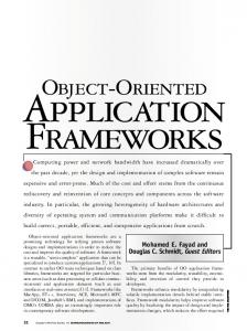
The requirements models, see Figure 1, includes: a process model which captures the functions the system must perform, a control model which describes the control of the system, and an information model which describes the data relationships within the system.
PROCESS MODEL
PROCESS SPECIFICATIONS
ND Y A HIP TIT NS S EN ATIO TION L A RE IFIC C E SP
DICTIONARY
SP CO EC NT IFIC RO AT L ION S
In fact, specifications are typically in the form of a Statement of Work and Requirement Specification. Therefore, the system to be built must be understood in terms of requirements (functions the system must perform). This naturally leads to a structured analysis, at least at the top level. Specifically structured methods (functional decomposition) provide a natural vehicle for discussing, modeling and deriving the requirements of the system. The main advantage of structured analysis is in the development of a complete system requirements model. Having a complete requirements model on one diagram helps ensure that all requirements are allocated to architecture components. The primary (fatal) flaw with structured methods is that they do not readily support the use of COTS or reusable modules. The top down process works well for new development, but does not provide the mechanisms for “designing in” the use of COTS or existing components. The top down process of functional decomposition does not lead to a set of requirements which map well to existing components. When the requirements don’t map cleanly, there are two choices: either don’t use the existing components or force fit the requirements to the existing components and “somehow” deal with the requirements which are only partially covered by the existing components. Neither of these approaches lead to a good systems design.
INFORMATION MODEL
CONTROL MODEL
Figure 1, Hatley-Pirbhai Requirements Models The architecture models, see Figure 2, include a Architecture Flow Model which shows data flows between architecture components, and an Architecture Interconnect Model which shows how the architecture components are physically connected. The two architecture models support sizing and performance modeling. In fact, CACI provides a tool (VeriSpec/RA) which interprets the Hatley-Pirbhai models directly and generates a performance model semi-automatically. Since all interfaces between components are shown on the Architecture Flow Model, system coupling is easily seen. With this approach both module coupling and functional cohesion are shown on one diagram greatly aiding in the determination of “goodness” of the design.
IF4
AM2
IF1
AM2
IF6 IF5
AM1
AM3 IF3
IF2 AM4
IF7
AM1 IF8
AM3
AC1 AC2 AC3
AM5
AM4
AM5
ARCHITECTURE INTERCONNECT DIAGRAM
ARCHITECTURE FLOW DIAGRAM
ARCHITECTURE DICTIONARY ARCHITECTURE MODULE SPECIFICATION
ARCHITECTURE INTERCONNECT SPECIFICATION
Figure 2, Hatley-Pirbhai Architecture Models Another key concept and real strength of H-P is the concept of an enhanced requirements model, see Figure 3. The basic concept is that every time you make a design decision you potentially add new derived requirements. For example, if it is decided to put components that interface to each other in different computers, you have now added derived requirements for network communications. The other type of requirements which show up on the enhancement requirements model are related to building a system in a non-perfect world. Examples of requirements of this type are security, availability and maintenance. For example, in a perfect world, components would never fail. In the real world, components do fail and if the system requirements call for high availability of a function, redundancy must be provided in case of failure. These types of requirements are identified and modeled in the H-P methodology in the enhanced requirements model. ENCODE/DECODE TRANSFORMATIONS USER INTERFACE PROCESSING INPUT PROCESSING
REQUIREMENTS MODEL
OUTPUT PROCESSING
DECODE TRANSFORMATIONS
LOGICAL (TECHNOLOGY INDEPENDENT) TRANSFORMATIONS
ENCODE TRANSFORMATIONS
ENCODE/DECODE TRANSFORMATIONS MAINTENANCE & SELFTEST
Figure 3, Enhanced Requirements Model
The Enhancements are important in reuse designs because this is where the derived requirements for the “glue” code needed to link existing components together are identified, modeled and understood. The Enhanced Data Flow Diagram (DFD) contains all high level requirements and all high level interfaces. A traceability matrix from the Requirements Specification is made to this model. The enhanced requirements model is used to allocate requirements, interfaces, data stores and control to the architecture components. Combining Object-Oriented Methodology into Hatley-Pirbhai. Combining H-P with OO provides all of the tools needed to design any system. While H-P as originally developed does not discuss OO, the H-P methodology inherently supports OO design and analysis. The OO models are combined with H-P in several places. First, the OO Class Model replaces the H-P Information Model. Second, Use Cases and Collaboration Diagrams are used to show how the system will operate. Finally, the OO Class model is used as an architecture model for software modules during software design. Other OO diagrams are used, as needed, to design the OO software. The Process for combining OO and Structured Methods. The recommended starting point is the development of the system context diagram. This step is important for two reasons. First, it’s impossible to design a system without understanding its’ inputs and outputs. Second, by identifying the external interfaces up front, the process of coordinating and working out the details of the external interfaces, often a time consuming and difficult task, can start immediately. The second step depends on the system to be designed, the constraints of the system and the background of the designers. Below is a list of the steps for this process. The order of the steps shown below is typical, but not mandatory. Analysis and Design Steps2 • Build context diagram • Use functional decomposition to partition requirements • Build an OO model to understand data relationships 2
Trades, studies, building prototypes and technology research are a key part of systems design, but they are not described here.
• •
•
• • • •
Build a control model to specify control Enhance the requirements and control models to address a non-perfect world and design decisions Group requirements and allocate all requirements, data stores and control to architecture components Build the architecture flow diagram Build the architecture interconnect diagram Model the system performance3 Iterate the above steps until a good design has been created for this level of the architecture and the models are all consistent with each other.
Note: It makes no difference where y o u start, the key is to make sure that a l l models integrate at some point in time. In this approach, the first appearance of an OO model is as a replacement for the information model (ER diagrams) in the H-P requirements model set. The OO model here does not imply (as it does in a strictly OO methodology) that the objects are architecture components. At this time, the OO model is used only as an information model. The OO model is used to populate the data dictionary and to provide insight into the data relationships of the system. The first level architecture for a large system is typically subsystems (for example, an archive management subsystem; containing one or more computers, a robot and multiple readers/writers). The architecture can be developed using either a bottom up or top down approach. If there are components which already exist (COTS, GOTS or reuse items) and the components are clearly going to be part of the system design, these should be “taken as a given” and included in the architecture right away. The requirements partitioning needs to reflect that architecture decision. In other words, if only part of a function (a bubble on a DFD) can be satisfied by an existing component, the function must be split in the requirements model so that the requirements not met by the existing component are clearly identified. For requirements that cannot be allocated to existing components, these modules can follow directly from the requirements model and good engineering practices (e.g., minimize coupling and maximize functional cohesion). Typically both top down and bottom up approaches are needed in any large system. 3
The Data Dictionary is populated as each of the models are being developed.
This approach handles cases where some requirements cannot be met by existing components via two separate processes. First, since all requirements appear on the enhanced DFD, it becomes clear which requirements are handled by existing components and which need to be addressed elsewhere. The second step is to re-look at the enhanced model when architecture decisions are made. Specifically, when an existing component is selected as an architecture component, you reevaluate the requirements to see if there are any new derived requirements caused by that architecture decision. Very often, code must be developed to interface existing components/COTS to each other. This process, requirements analysis though architecture design, is then repeated for each component of the highest level architecture (i.e., the subsystems). Each subsystem is treated as a new system to be designed and the 10 step process repeats. Note that not all steps have to be performed at all levels (this is a tool box approach). If the subsystem is not data driven (e.g., a communications subsystem), then the OO model may not be needed for that subsystem. When the architecture is defined down to the level of designing software Configuration Items (CIs), a choice can be made to use OO for that CI or a structured design. Reasons for choosing one over the other might be performance, requirements volatility, or reuse potential. Modules which do not have clearly defined requirements or are subject to change (e.g., user interfaces) are good candidates for OO. Other modules which require high performance and have clearly defined requirements (e.g., drivers) may be better served by a more traditional design. When it has been determined that a particular software module is going to be designed using OO, the OO model is used as the architecture model for that software component. OO Designs and Structured Designs are fundamentally Different. The fundamental difference between an OO design and a structured design is how control is handled. In a structured approach, control is modeled separately from functions. A good structured design has a single “smart” controller that performs only control functions and many worker components that do the work. This is analogous to military model, where a commander makes decisions and soldiers follow orders and perform the work. In an OO design, control is partitioned into each object (i.e., each component is designed to stand-
alone). This is a service-oriented approach. To accomplish a given task, you have to go and get the services you need from different service suppliers (i.e., objects). The structured approach is very efficient. Things get done quickly and efficiently. The problem with this approach is that the components are tightly integrated in this design. While typically, the design is flexible enough to handle requirement changes within a given system, the design is not well suited for reuse in a different domain. On the other hand, the OO design is very flexible and can be easily reused – but it is not as efficient. Therefore, trades need to be performed to determine which approach to use on each part of the system. Note that within one system, both approaches can be used. Performing both structured and objectoriented analysis provides a better design. One major advantage of following this approach is that regardless of which design (OO or structured) you end up implementing, you can come up with a much better solution by looking at the problem from both a structured approach and an object oriented approach. For example, by doing structured analysis and design, you can find ways make an object oriented design more efficient – without sacrificing flexibility or reuse. It’s also typically that you can develop a more flexible/reusable-structured design by seeing how the system would be implemented using an objectoriented approach. Conclusion. Systems engineering has changed significantly over the last 10 years. In the past we typically designed and developed large systems from scratch. Those days are gone. Today systems have to be built faster, cheaper, and they have to be more flexible than the systems in the past. To build today’s systems, we have to rely on COTS and reuse. This new focus requires us to use new methods and techniques. Methodologies like object oriented analysis and design can help with some of the problems, but also bring new challenges. We need to be able to blend proven systems design techniques, like Hatley-Pirbhai, with new reuse based methodologies. We have to expand our “toolbox” to include a wide variety of techniques to design these systems. The process described in this paper provides a complete set of systems engineering techniques that can be used to address the challenges of designing systems today.
References Hatley, Derek J. and Pirbhai, Imtiaz A., Strategies for Real-Time System Specification, Dorset House Publishing, 1988. Biography. Mr. Rickman has over 20 years of systems engineering experience related to the design and development of large information systems. At present, Mr. Rickman is the Systems Engineering Process Owner for Raytheon Systems Company in Reston, VA.