BIOMICROFLUIDICS 3, 044114 共2009兲
A programmable microvalve-based microfluidic array for characterization of neurotoxin-induced responses of individual C. elegans Hui Ma, Lei Jiang, Weiwei Shi, Jianhua Qin,a兲 and Bingcheng Lina兲 Dalian Institute of Chemical Physics, Chinese Academy of Science, Dalian, Liaoning 116023, People’s Republic of China 共Received 6 November 2009; accepted 18 November 2009; published online 23 December 2009兲
The soil dwelling nematode Caenorhabditis elegans 共C. elegans兲 is an excellent model organism for the study of numerous disease including neurodegenerative disease. In this study, a programmable microvalve-based microfluidic array for real-time and long-term monitoring of the neurotoxin-induced responses of the individual C. elegans was developed. The device consisted of a flow layer and a control layer, which were used for worm manipulation. By activating the programmable microvalves in the control layer, mutiple worms could be individually captured and intermittently immobilized in parallel channels. Thus the mobility behavior, together with the corresponding dopaminergic neuron features of the worms in response to neurotoxin, could be investigated simultaneously. It was found that the neurotoxin MPP+ enabled to induce mobility defects and dopaminergic neurons loss in worms. The established system is easy and fast to operate, which offers not only the controllable microenvironment for analyzing the individual worms in parallel, monitoring the same worm over time, but also the capability to characterize the mobility behavior and neuron features in response to stimuli simultaneously. In addition, the device enabled to sustain the worm culture over most of their adult lifespan without any harm to worm, providing a potential platform for lifespan and aging research. © 2009 American Institute of Physics. 关doi:10.1063/1.3274313兴
I. INTRODUCTION
The soil dwelling nematode Caenorhabditis elegans 共C. elegans兲 is an excellent model organism for a variety of biological studies due to the unique characteristics of its development, genetics, and neurology. In particular, the basic composition of neurotransmitters, synaptic proteins, and ion channels are highly conserved between C. elegans and human beings, which makes it an effective tool for investigating the multicellular processes, numerous diseases 共e.g., neurodegenerative disease兲, and drug discovery.1,2 Because of the high mobility of the worms, effective immobilization is often required for the better observation and imaging of specific neurons during the studies of neurobiology. Traditionally, glue and anesthetics are used for immobilizing the C. elegans;3–5 however, these methods are time consuming, which often require manual operations. They also lead to potential toxicity and irreversibility, limiting the use for the real-time and long-term monitoring of the responses of worms to stimulus. Therefore, a new approach that enables to manipulate the individual worms conveniently, harmlessly, as well as reversibly is highly desirable. Microfluidics has recently aroused increasing interests in C. elegans study attributed to its benefits including miniaturizing and integrating various operations by flexible, and especially the perfect match with the size of worms at microscale dimension. Microfluidics-based C. elegans
a兲
Authors to whom correspondence should be addressed. Electronic addresses:
[email protected] and
[email protected].
1932-1058/2009/3共4兲/044114/8/$25.00
3, 044114-1
© 2009 American Institute of Physics
044114-2
Ma et al.
Biomicrofluidics 3, 044114 共2009兲
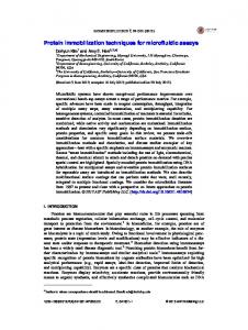
FIG. 1. Schematic of the microvalve-based microfluidic device for monitoring C. elegans. 共a兲 Layout of the microfluidic device, which is composed of upper flow layer and lower control layer. 共b兲 Schematic of the overall structure. 共c兲 A magnified view of two imaging channels in the microfluidic device.
studies have been carried out for maze exploration,6 oxygen sensation,7 phenotype and genetic screenings,8,9 automatic cultivation,10 and individual movement assay.11 In addition, some microfluidic systems, which utilized the microfabricated tapered channels12,13 or microvalves14–17 for imaging analysis, have been reported as well. However, real-time and long-term monitoring of the individual worms in response to stimulus in terms of mobility and neuron features still imposes a challenge. In this study, we demonstrated a programmable microvalve-based microfluidic array for realtime and long-term monitoring of the neurotoxin-induced responses of the individual C. elegans. The mobility behavior and the corresponding dopaminergic neuron features of the worms were investigated simultaneously. The programmable microvalves were incorporated to manipulate individual worms, and each microvalve could be adjusted according to the specific requirement of its closed state and speed. Multiple worms were individually captured, immobilized, and released under flexible control by using the design, which enabled to realize the real-time monitoring of the worms for a long term. The established system could immobilize and release the same worm repeatedly, facilitating the continuous monitoring and tracking the responses of worms to chemical stimulation at single-animal resolution, thus, providing a potential platform for screening of chemical compounds. II. EXPERIMENTAL A. Microfluidic device fabrication
The microfluidic device 共shown in Fig. 1兲 was fabricated in polydimethylsiloxane 共PDMS兲 共Sylgard Silicone elastomer 184, Dow Corning Corp. Midland, MI兲 by a rapid prototyping method18 and utilized the well-established “PDMS flow-control layer” technique.19 The flow layer master was prepared on a glass wafer by spinning SU-8 3035 negative photoresist 共Microchem Corp, Newton, MA兲 at a thickness of 80 m in distribution channels and 45 m in imaging channels, respectively, and patterned by photolithography. The control layer master was patterned in a same way and the thickness was 35 m. PDMS base and curing agent with two different mixing ratios 共5:1 and 10:1 by mass兲 were mixed thoroughly and degassed under vacuum. The PDMS with 5:1 ratio was used to create the flow layer, and the PDMS with 20:1 ratio was to create the control layer. The flow layer was peeled off from the SU-8 master and subsequently bonded to the control layer at 80 ° C for at least 2 h. Then, the two-layer PDMS replica was peeled off from the glass wafer and trimmed to size. Finally, the PDMS slab was bonded irreversibly to a glass cover slip using air plasma.
044114-3
Individual C. elegans assay
Biomicrofluidics 3, 044114 共2009兲
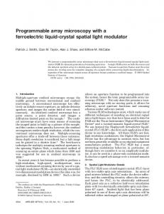
FIG. 2. The operation processes of the microvalves for immobilizing and releasing of worms on chip. 共a兲 The worm was loaded into the imaging channels 共valves A and B were switched on兲; 共b兲 the worm was trapped into the imaging channel 共valve A was switched off兲; 共c兲 the worm was immobilized for imaging 共valve B was switched off兲; 共d兲 the worm was released after imaging 共valve B was switched on兲.
B. Worm culture and treatment
Wild-type N2 and transgenetic strain UA57 共genotype was baIn4兲 C. elegans were obtained from the Caenorhabditis Genetics Center at the University of Minnesota 共St. Paul兲 and was cultivated as described by Brenner.20 Briefly, worms were cultivated at 20 ° C on nematode growth medium 共NGM兲 agar seeded with Escherichia coli OP50 共food兲. Prior to seeding, bacteria were incubated overnight at 37 ° C. For the neurotoxin-induced response assays, a suspension of L1 UA57 worms with bacteria in NGM was distributed into 96-well microtiter plates containing 1-methyl-4-phenylpyridinium 共MPP+兲 共Sigma, St. Louis, MO兲 at various concentrations 共0, 0.5, and 1.0 mM兲, the plates were incubated at 20 ° C until the worms reached adulthood stage, and then analyzed. For the postimmobilized survival test, the adult N2 worms captured in the imaging channels were flushed out and collected by applying positive pressure to the syringe connected to the outlet, the postimmobilized worms were then transferred to a fresh Petri dish, and the day of transferring was defined as 0 day. We monitored the survival of the worms for the subsequent up to 4 days. The test population consisted of 22 worms that were immobilized and released five times 共the immobilizing time is about 5 min for each time兲, and the control population consisted of 24 worms that were not run through the device. Both populations were monitored once a day for dead animals. An animal was scored as dead if it did not respond to prodding with a platinum worm pick. C. Worm loading and manipulation
Adult worms were collected and added to the inlet. By applying negative pressure to the syringe connected to the outlet, the worms were loaded into the imaging channels. The immobilizing and releasing individual worms were achieved by activating the two programmable microvalves 共valves A and B in Figs. 1 and 2兲 in the control layer. The programmable microvalves were controlled using the stepping motor. D. Worm mobility behavior analysis
The mobility behavior of individual worms in response to the neurotoxin was recorded using an inverted fluorescent microscope 共Olympus IX 71, Japan兲. After being captured into the imaging channels, the worms were allowed to acclimate for 30 s, and then the number of their body bends in 20 s intervals was recorded for each worm. Three independent experiments were performed at each condition. E. Fluorescence imaging
The green fluorescent protein 共GFP兲 expression in transgenetic strains UA57 in response to the neurotoxin was examined using the same inverse fluorescence microscope with excitation wavelengths at 470–495 nm and detection wavelengths at 510–550 nm. The fluorescence images were analyzed using image processing and analysis software 共IMAGE-PRO, Media Cybernetics, USA兲.
044114-4
Ma et al.
Biomicrofluidics 3, 044114 共2009兲
III. RESULTS AND DISCUSSION A. Microfluidic device design and operation for worm manipulation
In this work, a programmable microvalve-based microfluidic array was designed to manipulate the individual worms, and the schematic of the device was shown in Fig. 1. It consisted of a flow layer and a deformable PDMS membrane, which served as a control layer. In the flow layer, there were two functional units, including the distribution channels and the imaging channels. The worms were loaded from a tapered distributing channel 共from 100 to 70 m in width兲 to a wider 共250 m in width兲 channel for immobilizing and imaging, and a parallel channel design was implemented to benefit for the analysis of multiple worms at same time. In most cases, the tapered end of the distributing channel was sufficient to limit a single worm within one of the imaging channels. The two narrow grooves 共30 m interval distance兲 at the end of the imaging channel were designed to prevent the captured worm from escaping from the imaging channel. In the control layer, two programmable microvalves were activated to manipulate the worms, and valve A was designed for trapping the worms, while valve B for immobilizing the worms. The operation processes for each step were illustrated in Fig. 2. 共a兲 Before the worms entered the imaging channel, both valves A and B were switched on in order to form the continuous worm flow. 共b兲 Once the worms were loaded into the imaging channels, valve A was switched off immediately to prevent the worms from escaping. At that time, valve B was still open, the total height of imaging area was 80 m 共the height of control channels was involved兲, which was sufficient for the free movement of the worms. 共c兲 For imaging, valve B was switched off gradually to immobilize individual worms in a linear position. 共d兲 After imaging, valve B was switch on. By repeatedly switching valve B, the real-time imaging and the long-term monitoring of the individual worms could be obtained. B. Microfluidic device performance validation
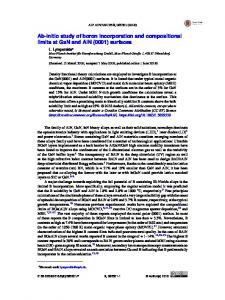
Prior to characterization of the neurotoxin-induced responses of individual worms, adult N2 worms were used to verify the performance of the proposed microfluidic device. Commonly, the captured worm retained high mobility until the pushed-up PDMS membrane restricted its movement space. By continuously pushing up the deformable PDMS membrane 共switching off valve B兲, the worm was squeezed to the side of the imaging channel and its movement could be fully restricted. The finely immobilized worm recovered its mobile activity quickly after the PDMS membrane was pushed down 共switching on valve B兲. A series of images for the immobilizing and releasing process were shown in Fig. 3共b兲共i兲 and Fig. 3共b兲共iii兲 共enhanced兲. By controlling the incorporated microvalves, the device was able to capture individual worms into parallel channels for immobilizing and imaging conveniently 关Fig. 3共c兲兴. The processes for loading and immobilizing multiple worms were accomplished within 30 and 20 s, respectively, which were much faster than conventional methods. As the cross sections of channels were rectangular, the formed gap between PDMS membrane and channel walls made the captured worms able to get the liquid medium 共nutrient and stimulus兲, thus, maintaining the nutrient conditions of worms during longterm monitoring. In this design, by maintaining the individual worms in separate imaging channels and supplying nutrient delivery, the device was enabled to perform long-term culture up to 7 days without harm to the worms. To further demonstrate the feasibility of the proposed device for long-term imaging, we performed a postimmobilized survival test. Both the test and control populations were monitored for 4 days. We did not observe any morphological and movement defects or premature death in test populations 共data are not shown兲. C. Characterizing the neurotoxin-induced responses of individual worms
Based on the above work, the responses of the individual worms to neurotoxin were further characterized by using the microfluidic device. MPP+ has been reported to cause Parkinson dis-
044114-5
Individual C. elegans assay
Biomicrofluidics 3, 044114 共2009兲
FIG. 3. 共a兲 Photograph of the microvalve-based microfluidic device used in this experiment. 共b兲 Photographs of a single worm 共i兲 before 共enhanced兲关URL: http://dx.doi.org/10.1063/1.3274313.1兴, 共ii兲 during, and 共iii兲 after 共enhanced兲关URL: http://dx.doi.org/10.1063/1.3274313.2兴 immobilization. 共c兲 Photograph of the adult worms immobilized within the microchannels. The immobilized worms were marked by arrows.
easelike symptoms in vertebrates by selectively destroying dopaminergic neurons.1 In this study, a transgenic strain UA57, which expressed strong and specific green fluorescence in all eight dopaminergic neurons, was used for the following work. 1. Mobility defects induced by MPP+
We first characterized the mobility behavior of individual worms in response to MPP+. After the worms were individually loaded into the imaging channels, we immediately switched off valve A, while maintaining valve B open, the mobility behavior of the individual worms were recorded and analyzed. Typically, the untreated worms exhibited free movements with more often sine wave-shape and C-shape movement states 关Fig. 4共a兲共i兲 共enhanced兲兴 in the imaging channels,
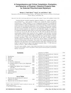
FIG. 4. Mobility defects induced by the MPP+. 共a兲 Representative images of mobility shapes of the worms treated with MPP+ at different concentrations, 共i兲 0 mM MPP+ 共enhanced兲关URL: http://dx.doi.org/10.1063/1.3274313.3兴, 共ii兲 0.5 mM MPP+ 共enhanced兲关URL: http://dx.doi.org/10.1063/1.3274313.4兴, and 共iii兲 1.0 mM MPP+ 共enhanced兲关URL: http:// dx.doi.org/10.1063/1.3274313.5兴. 共b兲 The histogram of the stroke frequency of the worms treated with MPP+ at different concentrations. Error bars represented standard deviation from three independent experiments.
044114-6
Ma et al.
Biomicrofluidics 3, 044114 共2009兲
FIG. 5. Dopaminergic neuron features induced by the MPP+. 共a兲 Fluorescence images of the worms treated with MPP+ at different concentrations, 共i兲 0 mM MPP+, 共ii兲 0.5 mM MPP+, and 共iii兲 1.0 mM MPP+. 共b兲 The histogram of the relative fluorescence intensity in dopaminergic neurons of the worms treated with MPP+ at different concentrations. Error bars represented standard deviation from three independent experiments.
whereas the worms after MPP+ treatment were subjected to mobility defects, such as slow, titanic, and coiled movements 关Fig. 4共a兲兴. The correlative analysis of the stroke frequency of individual worms associated with MPP+ concentration was shown in Fig. 4共b兲. As shown in Fig. 4共b兲, the stroke frequency of worms decreased with the increased concentration of MPP+. We also found that in most cases, the worms treated with 0.5 mM MPP+ only exhibited slow mobility without obvious change in their movement state 共sine wave-shape and C-shape兲 关Fig. 4共a兲共ii兲 共enhanced兲兴; but the situation was significantly changed in worms treated with 1.0 mM MPP+, not only the slow stroke frequency but also the coiled or titanic state 关Fig. 4共a兲共iii兲 共enhanced兲兴 were observed. From the results shown in Fig. 4, we could easily concluded the MPP+ induced different mobility defects of the worms and the phenotypes could be characterized at single-animal resolution. 2. Dopaminergic neurons features induced by MPP+
After the mobility behaviors were evaluated, the dopaminergic neuron features of the worms in response to MPP+ were subsequently characterized. By gradually switching off valve B, the captured worms were immobilized in a linear position for imaging, and their GFP expression in eight dopaminergic neurons were imaged and analyzed. As shown in Fig. 5共a兲, the untreated worms expressed intact and strong GFP expression in all eight dopaminergic neurons. As a comparison, the worms treated with 0.5 mM MPP+ showed significant reduction or complete loss of GFP expression in the dendrites of dopaminergic neurons with the retention of GFP expression in cell soma, and a more significant reduction in GFP expression in the dopaminegic cell bodies was observed in the worms treated with 1.0 mM MPP+. The relative fluorescence intensity of GFP expression in the individual worms treated with MPP+ at different concentrations was shown in Fig. 5共b兲, and the degree of GFP expression related to MPP+ was dose dependent. Coupled with the mobility analysis results, the worms with no mobility defects showed intact and strong GFP expression, and the worms with different mobility defects showed a reduction in GFP expression, suggesting that the mobility defects were closely related to a reduction in GFP expression in dopaminergic neurons. 3. Real-time monitoring of the dopaminergic neuron features in individual worms
The neurotoxic effect of MPP+ on dopaminergic neurons was further characterized by monitoring the GFP expression in dopaminergic neurons in real time. Based on the preliminary work, we chose 4 h as the monitoring time duration, which was sufficient for observing the continuous attenuation of GFP expression in the MPP+ treated worms. The captured worms were intermittently immobilized for imaging by repeatedly switching valve B, and the fluorescent photographs were taken at every 1 h interval for a continuous period of 4 h. The attenuated GFP expression
044114-7
Individual C. elegans assay
Biomicrofluidics 3, 044114 共2009兲
FIG. 6. Real-time monitoring of the dopaminergic neuron loss in the worms treated with MPP+ at different concentrations.
suggested the potential neurotoxicity of MPP+ on dopaminergic neurons 共Fig. 6兲. Furthermore, the attenuated GFP expression, expressed by the relative fluorescence intensity, was observed in timeand dose-response manners 共Fig. 7兲. As shown in Fig. 7共d兲, after treated with MPP+ at different concentrations 共0.5 and 1.0 mM兲, the relative fluorescence intensity in the worms decreased to 79.19% and 67.07%, respectively. Due to the individual difference, worms of same genotype might show different responses to stimulus. During the experiment, we noticed the obvious differences among the individual worms tested 关Figs. 7共a兲–7共c兲兴, indicating the special ability of this device for tracking the responses of individual worms to stimulation over time. In such a case, the unique characteristics from the individual worms can be obtained, which is not possible by using the traditional methods.
FIG. 7. The curves of the relative fluorescence intensity in dopaminergic neurons of individual worms and total worms. 共a兲–共c兲 represented the relative fluorescence intensity of the individual worms randomly selected from the total worms: 共a兲 0 mM MPP+, 共b兲 0.5 mM MPP+, and 共c兲 1.0 mM MPP+. 共d兲 represented the average relative fluorescence intensity from the total worms. Error bars represented standard deviation from three independent experiments.
044114-8
Ma et al.
Biomicrofluidics 3, 044114 共2009兲
IV. CONCLUSIONS
We have demonstrated a new programmable microvalve-based microfluidic device for the analysis of individual C. elegans with more flexibility. The established system is simple and fast to operate, which offers not only the controllable microenvironment for analyzing the individual worms in parallel, monitoring the same worm over time, but also the capability to characterize the mobility behavior and neuron features in response to stimuli simultaneously. This device could be potentially applied for whole animal assay and screening of antineurodegenerative drugs at singleanimal resolution. In addition, the capabilities of this device to maintain a long-term worm culture make it an attractive platform for lifespan and aging study.
ACKNOWLEDGMENTS
This work was supported by the National Nature Science Foundation of China 共Grant Nos. 90713014 and 20635030兲, the Ministry of Science and Technology of China 共Grant Nos. 2007CB714505 and 2007CB714507兲, and the Knowledge Innovation Program of the Chinese Academy of Sciences 共Grant No. KJCX2-YW-H18兲. E. Braungart, M. Gerlach, P. Riederer, R. Baumeister, and M. C. Hoener, Neurodegener. Dis. 1, 175 共2004兲. R. Nass, D. M. Miller, and R. D. Blakely, Parkinsonism Relat. Disord. 7, 185 共2001兲. 3 M. B. Goodman, D. H. Hall, L. Avery, and S. R. Lockery, Neuron 20, 763 共1998兲. 4 R. Kerr, V. Lev-Ram, G. Baird, P. Vincent, R. Y. Tsien, and W. R. Schafer, Neuron 26, 583 共2000兲. 5 J. A. Lewis, C. H. Wu, H. Berg, and J. H. Levine, Genetics 95, 905 共1980兲. 6 J. H. Qin and A. R. Wheeler, Lab Chip 7, 186 共2007兲. 7 J. M. Gray, D. S. Karow, H. Lu, A. J. Chang, J. S. Chang, R. E. Ellis, M. A. Marletta, and C. I. Bargmann, Nature 共London兲 430, 317 共2004兲. 8 K. H. Chung, M. M. Crane, and H. Lu, Nat. Methods 5, 637 共2008兲. 9 M. M. Crane, K. Chung, and H. Lu, Lab Chip 9, 38 共2009兲. 10 N. Kim, C. M. Dempsey, J. V. Zoval, J. Y. Sze, and M. J. Madou, Sens. Actuators B 122, 511 共2007兲. 11 W. W. Shi, J. H. Qin, N. N. Ye, and B. C. Lin, Lab Chip 8, 1432 共2008兲. 12 S. E. Hulme, S. S. Shevkoplyas, J. Apfeld, W. Fontana, and G. M. Whitesides, Lab Chip 7, 1515 共2007兲. 13 N. Chronis, M. Zimmer, and C. I. Bargmann, Nat. Methods 4, 727 共2007兲. 14 T. V. Chokshi, A. Ben-Yakar, and N. Chronis, Lab Chip 9, 151 共2009兲. 15 S. X. Guo, F. Bourgeois, T. Chokshi, N. J. Durr, M. A. Hilliard, N. Chronis, and A. Ben-Yakar, Nat. Methods 5, 531 共2008兲. 16 C. B. Rohde, F. Zeng, R. Gonzalez-Rubio, M. Angel, and M. F. Yanik, Proc. Natl. Acad. Sci. U.S.A. 104, 13891 共2007兲. 17 F. Zeng, C. B. Rohde, and M. F. Yanik, Lab Chip 8, 653 共2008兲. 18 J. C. McDonald, D. C. Duffy, J. R. Anderson, D. T. Chiu, H. K. Wu, O. J. A. Schueller, and G. M. Whitesides, Electrophoresis 21, 27 共2000兲. 19 M. A. Unger, H. P. Chou, T. Thorsen, A. Scherer, and S. R. Quake, Science 288, 113 共2000兲. 20 S. Brenner, Genetics 77, 71 共1974兲. 1 2