1B1.5
ICICS-PCM 2003 15-18 Decanber2003
-s
A Programming Framework for Service Association in Ubiquitous Computing Environments Enyi CHEN, Yuanchun SHI, Degan ZHANG and Guangyou XU The State Key Laboratoy of Intelligence System and Technology Department of Computer Science and Technology Tsinghna University, Beijing 100084 Email:
[email protected]&uaedum {shiyc, gandegangde, xgy-dcs}@mail.tsingh~.edu.~
Abstract In a ubiquitous computing environment, an application is a collection of services lied at runtime, which we call service association. To solve service-tc-service communication and interaction in service association, a novel programming framework is provided in this paper, which consists of two abstraction models Service Component Model (SCM) and Service Association Model ( S A M ) . According to S C N a service can be depicted as an XML document with semantic interface hy Service Description Language. Based on S A M , the relation of services can be dehed as a Service Dependency Graph, so that dynamic service association can be maintained at the runtime. To evaluate our programming 6’amework we are developing a prototype system called Intelligent Meeting Room.
-
1. Introduction Research in ubiquitous computing [l] is towards the development of an environment able to deal with the mobility and interactions of both usem and devices. For software running on ubiquitous computing enviroumen4 the abstraction requirements are twofold - intra-device absaaCtion and inter-device abstmction [2]. The first one is similar to today’s computers, solved by small operating system kernels. Additional constraints such as saeen size, memory size, CPU-performance, or power consumption may limit the application but basically intra-device absaacton has to deal with a static environment known at build time. The second one is a much bigger problem. Beside the decision of which services should be accessible fiom the outside, different hardware and software interfaces have to be considered. Additional difficultiesarise because the cooperating devices may be unknown, there are no standards to follow due to innovation, there is no global accessible state, and there is usually nothing l i e a “system administrator” keeping a birds eye view of the system. ubiquitous computing applications go beyond the services offered by a single device. An application running in such an environment is a collection of services linked at runtime, which we call service association. These associations may change during execution
0-7803-8185-8/03/$17.00 0 2003 IEEE
especially if the application is composed of services running on mobile devices, which may leave or join the application. Service association must solve the service-te service communication and interaction. One of the fundamental problems prohibiting service association is the lack of semantics in interfaces. By service component model and service description language, adding semantics to interfaces became thus one of goals of o w research. Additionally, we design service association model and service dependency graph to depict the relation of services and maintain the dynamic association at the runtime. Our research has dual purpose. For user, using an application and doing some useful works should not require to he an expert in the organization of the software infrastructure. For developers, hardware and protocol heterogeneity must be hidden fiom ubiquitous computing application as good as possible. The rest of this paper is organized as the following: section 2 gives a scenario about service association in a meeting room and explains its some design issues; section 3 describes service component model and service association model; section 4 introduces high-level service description based on XML language to add semantics to interface; section 5 discusses service association mechanism; section 6 gives the implementation of service association; and the final section ends with the conclusion.
2. Design Issues 2.1. Scenario In a meeting room, there are three persons, Xq Shi, and Chen, discussing “Research on Ubiquitous Compdng I! Each one takes a mobile device, which is IBM’s Thinkpad with Windows XP,Dell’s Latirwle with Linlrr, and HP’s iPAQ with Windows CE respectively. Each mobile device has a wireless communication module, such as PCMICA for 802.I1. Two display devices - two projectors attached with two PCs, and a wireless (AP) Access Point exist in the meeting room. Once they enter info i f , their mobile devices automatically connect with the AP. When one gives his presentation, he can easily use one projector to show his PPT Jilt?, rmd use another one to display complementary materials, for example, mapping his
202
desktop winabw, playing a video j l e or showing some image Jle. If the froor is swiiched f.om one person to another one, the corresponding presentation j l e and complementaiy moterials c m be easily switched to the two display screen. Tablel. DitTerent Services Service in Mobile Device I Service in Environment PPT control 1 PPT Display Desktop Send
Vid&S&d Image Send
I Desktop Show I Video Play I Image Show
In the above scenario, four services exist in each mobile device, and four corresponding services exist in the meeting room, as the table 1 shows. Not to break up meeting flow, service association between PFl-Display and PPT-Control should follow the floor. For example, when the floor is 6om Shi to Xu, Shi's PPT-Control becomes inactive but Xu's PFI-Control is activated, and not Shi's PPT file hut Xu's PFT file is projected by PPT-Display. To complement his presentation, sometimes Xu may play some video on the second screen, but sometimes Xu may show some image on the screen. It should be easy for Xu to realize these functions, as if to click a button on his laptop, or else his attention is attracted fiom the presentation task.
2.2. Different Communication Forms in Service Association
2.3. Device Heterogeneity One of the major challenges in building ubiquitous computing system is ensuring that it can scale to the large degree of heterogeneity present in ubiquitous computing environment. "he difficulty is that an application must explicitly how to intemperate with the massive variety of devices in real world ubiquitous environments. Even more challenging, new devices are being developed every day. To solve the device heterogeneity, adoption of standard protocol is helpful method for service association. For example, in the above scenario, each mobile device has its own OS. If we want to make an associatioo of user's desktop window with the second display device in the environment, we can use RFEi protocol. Consequently, the Destop-Show service presents uniform form though the corresponding desktop window has tbree types Windows XP, Lmux and Windows CE. Further, if the second display device changes from a projector to a TV, the service association of desktop window with the TV always works well as long as RFJ3 protocol is realized in the TV.Adoption of standard protocol can give another advantage - saving the development time and enhancing the application robustness. We enable utilization of the well-known communication protocols, such as H", RTP, RTSP or RFB, and easy deployment of new ones. This increased backward compatibility with the existing applications or middleware technologies, and forward compatibility with ones to be developed in the future.
2.4. Quality of Service (QoS)
To realize the above scenario, we need some communication mechanism to support service association. Service to service communication in the service association can be roughly classified into tbree forms: event communication, stream communication and bulk communication. Event communication occasionally happens and usually has high-level semantics, e.g. a command from PPT-Control asking PE-Display for page down or page up. The communication is sensitive to the loss of data, whereas the requirement 00 the delivery latency is . moderate, as long as it is within a reasonable boundary, say, 50 ms, according to the cognitive character of human. Stream communication constantly occurs. Their semantic level usually is relatively low and the drop of several data units is usually tolerable. However, they are sensitive to the variation of the delivery latency, while in most cases their requirement on the delivery latency is also moderate. An example is the delivery of video 60m Vido-Send to Video-Play in the above scenario. The requirement of data in bulk communication is between event communication and stream communication. An example is the delivery of image f i e fiom Image-Send to Image-Show in the above d o . To facilitate the developers to implement their ubiquitous application, our programming W e w o r k should include all tbree communication forms.
Uhiquitous computing promotes the proliferation of various statioxq, embedded and mobile devices interconnected by heterogeneous networks (e.g. wired, wireless, &ked). It leads to a more dynamic distributed computing environment than even before, where resource fluctuations, device changes are a common phenomenon rather than view as an extreme case. For example, in the future work, we will permit the participants join the Intelligent Meeting Room remotely in the above scenario. The remote participants may want to receive the live video of the meeting room. However, these remote participants have different client devices and Werent network connections. So the service association of Live-Video-Send with the remote participant's client device must be according to some QoS. Thus, a big challenge for the application developer is to build ubiquitous multimedia applications that are continuously and pervasively deliver multimedia contents with adequate quality to the user, in spite of resource fluctuations, device heterogeneity and user mobility.
3. Two Abstraction Models When we develop a ubiquitous application with a collection of services dynamically l i e d at the runtime. Two basic problems must to be solved. One is how to
203
define services, and the other is how to define their relation. Senice Component Model abstracts the service's ~ ~ d e l and service hsdation their relation. The data structure of the two models iS discussed in section 4 and section 5.
Produd the result COllsumed by task '. is a Source node that is not a consumer, but is a producer of some
3.1. Service Component Model
unit consisting of two vectors,
task. U is an end-user node that is not a producer of any task, but a consumer of some task. Each task is functional Qin
and
Qout,
and output quality vectors, respectively.
as its input and
is reward profile (see Fig 2(b)), representing a mapping from input quality and resource allocation to output
--
quality.
q ( ~ k )is
- -.
a single output qu&ty,
singe input quality. task.
-
'k
q(zk)
is a
is the resource allocation of the
Figl. Senice Component Model
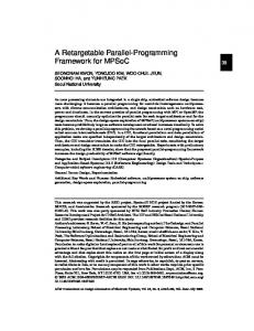
3.3. Two Examples We deploy layered model as our service component model. This model is corresponding to seven-layer Open Systems Interconnection (OSI) model, as the Figl shows. Several services can exist in a device, e.g. four services belong to a mobile device in the above scenario. Each service is called service widget (Serdget).The function of a service, such as how to play a video, is encapsulated in its inside, so the function is transparent for other service. But its event, stream or bulk communication is exposed to a network through a port which is a communication endpoint attached to the Serdget exploiting a well-know communication protocol. These pluggable protocol modules can be adopted through Port AFT by a service according to its requirement. In our prototype system, €I",RTP, RTSP and RFEl are implemented. A service is described as an XML document so that its semantics is understandable for other service. Section 4 will give the high-level service description in details. Service association, or service-to-service communication and interactioq comply with the Service Association Model in the next section.
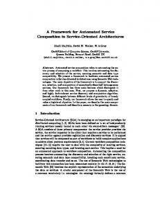
The above scenario is the overview of ongoing project Intelligent Meeting Room, which is next research plan about ubiquitous computing since our project Smart Classroom [SI is nearly finished To reduce the development difliculties, we don't take consideration of QoS and service arsociorion only includes an input service and an output service, but not any intermediate service. To explain the two models furtherer, we give two other examples of service association, as the Fig3 shows. One example is the service association about Video-onDemand POD) from video server to PDA (Fig3 (a)). Videosender in video server can deliver video data by RTP module on its portl. Videoplayer in PDA can receive video data by RTP module on its portl. Due to their different video data's QoS, they can not communication with each other directly. So VideoFiIter service is added in the association link to process video data Table 2 lists the different00s.
3.2. Service Association Model
11.
(bl
Fig3. Examples of Service Association Another example is the service association about VoiceEmail form Email server to user's mobile phone. Once the email server receives an email, it will send out its content (text) by Textsender's bulk module ("ITP or SMTP) on its portl. 'ITS service convert the content into speech audio and send the real time audio data by RTP module on its port2 to Soundplayer on mobile phone. Fig2 (b) shows the association link and Table 2 lists the different QoS.
(a) (b) Figt. Service Association Model We deploy the task-flow model as our Service Association Model. In the task-flow model (see Fig 2(a)), the relationship among tasks can be represented by a directed acyclic graph (DAG), called dependency graph. An edge Jiom task
Tk to
task
I ; mdmted . .
the
'k
204
1) For its good extensibility, developers can start with a
TableZ. QoS in Service Association Link VideoFilter Service
rough service structure and add detailed fields later without impacting prior works. 2) XML is user-iiiendly, for it is readable to human. Moreover, it is self-describing. 3) As an Internet standard, XML will facilitate to interopemte with other heterogeneous devices in future.
1 Table3. Port
Communication
Channels
mono
Eventh Stred BulkIn
Stream
4. High-level Service Description
Eventout
streamout
BllkOld
In a SDL document, the executed file name of the Serdget is specified in tag, and its ports and their aspects are defined give the attributes of the communication module on the port, which are nested in the tag. For the event communication, the tag.
So for the developer of ubiquitous application, he can construct a depederzq graph to depict the relation of services. Once the ubiquitous application run, the communication and interaction between services can look up the dependenq graph.
Fig4. An Example of Service Description Language High-level service description allows service developer to represent service in an XML document via Service Description Lmguuge (SDL). The adoption of XML has some significant advantages, such as:
m.
-
-.€ad
".-I
Fig5. Service Association Mechanism
205
JoinAsSource, LeaveAsSource, four interfaces: Subscribestream and UnsubscribeStream. In the above scenario, when Prof. Shi play a video on projector2's s a w , her Video-Send calls JoinAsSource interface and projector2's Video-Play calls SubscribeStream interface. For event communication, it has three interfaces: Publish, Subscribeand Unsubscribe. Service Repositoiy stores all possible services, which belong to an environment. Each service includes a higblevel service description and its executive code. For example, in the above scenario, four services PpT_Control, Desktop-Send, Video-Send and Image-Send - exist in the Service Repository. When the user enters into a environment, such as our Intelligent Meeting Room, the system will push all the possible services to usds mobile device or the user w illpull some service. When a service IUIIS,it will register its high-level service description in the Service Management. After parsing these semantic descriptions, Service Management will create a semantic graph to represent relations among all the services. In fact, service dependency graph in the previous section is maintained by Service Management. Acwrding to contextual information tiom Context Management, Association Management activates or disables some edges of semantic graph or some paths of service dependency graph. Context Mmagement contains tools to observe and use contextual information. Based on these contextual information, it attempt to discem what the user is currently engaged in and what she is trying to do. To accomplish this, we developed a formaliition called ContextLogic [9][10] for context representation and reasoning, built on the state of the art of the ht-order probabilistic logic and Bayesian Network. Its main ingredients includes: 1) A probabilisticrelation language to represent context data. 2) A ht-order probabilistic language, used to encode the knowledge base for context reasoning. 3) A context reasoning algorithm using Bayesian Network to the queried context data By careful design, ContextLogic has both sufficient expressive power and satisfying inference complexity. It has two interfaces - Context Query Interface and Context Event Subscription Interface. By the fyst interface, an application can query its wanted contextual information. An application can subscribe some events by the second interface. When these events happen, the application will fire some function. For example, in the above scenario, when the Sound Source Location (SSL) and vision-based person tracking module detect a participant is talking, an event pops up so that the participant's PE-Control is fired.
However, in ubiquitous computing system, the service association may be dynamic. We can list the all possible association path and add some wnstraints in the dependency g r q h . For instance, in the above scenario, Xu, Shi and Chen all can associate their PE-Control with PE-Display, but in a special moment only one person can associate his PPT-Control with the PE-Display, as the Fig5 shows. So we add a