ACKNOWLEDGMENTS
I would like to express my sincere gratitude and deep appreciation to my supervisor Asst. Prof. Dr. Arzu Gönenç Sorguç not only for her guidance, valuable suggestions, comments and continuous support throughout this research but also her encouragement and patience in developing my academic attitude. Thank you… Special thanks to Dr. Chris Williams for his guidance, support and hospitality during my research in the University of Bath, England and thanks to Prof. Dr. Julian Vincent who provide me giving a seminar to share my experiences and knowledge with the colleagues from Biomimetic Research Centre in the same University. I also express my thanks to my colleague Alex for his help in the program writing process of the study. For the technical part of the simulations I am thankful to Murat Sorguç and Ömer Öztan from TAI. Also, special thanks to Türkiye Çimento Müstahsilleri Birliği, who awarded my PhD research with “İz Bırakanlar” Scholarship for 2 years (2005-2007). I am forever indebted to my lovely mother Emine Arslan, my beloved father Osman Arslan, my darling sister Sema Akdemir and my dearest brother Ömer Arslan for their encouragement, trust and self-sacrifice throughout all my life and I am sincerely thankful to them for always believing in me. My gratitude can never be enough. Thank you… I would like to express my deepest appreciation to my husband Mustafa, for being always with me, his unshakeable faith in me and his endless support, patience, love and friendship. He always shared my excitements and enthusiasm. Thank you…and finally… to Zeynep Nur… my lovely baby deserves more than gratefulness with her existence in my life. Without her inspiration and love I could not have finished this study. Thank you my sweetheart...
TABLE OF CONTENTS
CHAPTER 1. INTRODUCTION ............................................................................................................. 1 1.1 Argument .................................................................................................................... 1 1.2 Objectives and Scope ................................................................................................ 3 1.3 Procedure ................................................................................................................... 4 1.4 Disposition .................................................................................................................. 6 2. LITERATURE SURVEY ................................................................................................... 8 2.1 The concept of Biomimesis ........................................................................................ 9 2.1.1 Why and How Biomimesis Works ...................................................................... 11 2.2 Nature-Architecture Relationship.............................................................................. 15 2.2.1 Observation of Prior Periods .............................................................................. 15 2.2.2 Architectural Trends Inspired from Nature in 20 th Century ................................. 17 2.2.3 Inspirations from Nature in Contemporary Architecture ..................................... 25 3. THEORIES AND POSTULATE ...................................................................................... 32 3.1 Biomimesis in Architecture ....................................................................................... 33 3.1.2 Biomimesis in Architecture:................................................................................ 34 3.1.2.1 Classification of Structures in Nature .......................................................... 35 3.1.2.2 General Taxonomy of Architectural Structures Inspired by Nature ............. 37 3.1.1.2.1 Tree -Like Structures ............................................................................ 39 3.1.1.2.2 Skeleton-Like Structures....................................................................... 41 3.1.1.2.3 Web-Like Structures ............................................................................. 43 3.1.1.2.4 Pneumatic Structures ........................................................................... 44 3.1.1.2.5 Shell-Like Structures............................................................................. 47 3.2 Contemporary Biomimetic Approach in Architecture: A Case on Shell .................... 51 3.2.1 Definitions on Natural and Man-Made Shells ..................................................... 52 3.2.2 The Origins of Man-Made Shells ....................................................................... 54 3.2.3 Basic Structural Properties of Shells.................................................................. 55
3.2.4 Experimental Shell Structures and Shell Builders of the 20 th Century ............... 58 3.2.4.1 Pioneering Examples .................................................................................. 59 3.2.5 Present Techniques in the Analysis of Shell Structures ..................................... 66 3.3 Concluding Remarks of Chapter3 ............................................................................ 70 4. MATERIALS AND METHODOLOGY ............................................................................. 71 4.1 Materials................................................................................................................... 72 4.2 Methodology ............................................................................................................. 73 5. CASE STUDY: (RE)DISCOVERING (SEA)SHELL ARCHITECTURE .......................... 75 5.1 Observation of Shell Forms Inspired from Nature .................................................... 76 5.2 Analysis of Seashells and Seashell Geometry ......................................................... 86 5.2.1 Mathematical Studies on Seashell Geometry .................................................... 86 5.2.2 Modeling Approaches on Seashell Geometry .................................................... 88 5.3 Computational Model Developed for the Coiled Seashells ....................................... 92 5.3.1. Mathematical Analysis of the Selected Seashell: Turitella Terebra .................. 95 5.3.2 Mathematical Model of Turitella Terebra ........................................................... 97 5.4 Behavioral Analysis of Seashell(s) ......................................................................... 106 5.4.1 Analytic and Numerical Properties of Turitella Terebra .................................... 107 5.4.2 Physical Compression Tests on Turitella Terebra ........................................... 109 5.4.2.1 Preparation of Samples for Compression Tests ........................................ 112 5.4.2.2 Results ...................................................................................................... 122 5.4.3 Finite Element Analysis of Computational Model ............................................. 123 5.4.3.1 Preparation of Digital Model for FEA ......................................................... 124 5.4.3.2 Specifying Material Properties, Loads and Boundary Conditions .............. 126 5.4.3.3 Results ...................................................................................................... 129 5.5 Synthesis: Introduction to Non-Dimensional Parameters ....................................... 132 6. DISCUSSIONS AND CONCLUSIONS ........................................................................ 138 6.1 Conclusions .......................................................................................................... 138 6.2 Introducing Non-Dimensional Parameters ............................................................ 141 6.3 Recommendations for Future Studies................................................................... 147 REFERENCES ................................................................................................................ 149
LIST OF TABLES
Table 2.2 Time line representing Biomimetic studies and resulted innovations ......... 14 Table 2.2 Changing paradigm in nature architecture relationship ............................... 31 Table 3.1 Diagram representing architectural structures inspired by nature ............... 50 Table 5.1 Coefficients found in the vertical section of Turitella Terebra...................... 97 Table 5.2 Base, height and whorl numbers of each specimen ................................. 111 Table 5.3 Dimensions and test results of sample ID109 ........................................... 114 Table 5.4 Dimensions and test results of sample ID40 ............................................. 116 Table 5.5 Dimensions and test results of sample ID-115.......................................... 118 Table 5.6 Numeric values of base, height, weight, whorl numbers, time for failure, load and stroke for 43 samples (part 1) ............................................................................ 120 Table 5.7 Numeric values of base, height, weight, whorl numbers, time for failure, load and stroke for 43 samples (part 2) ............................................................................ 121 Table 5.7 Typical physical properties of calcium carbonates ................................... 127 Table 5. 8 Representing base-height ratio range to load ........................................ 133 Table 5. 9 Representing base-height ratio range to load relation for the “a” parts of the sample space...................................................................................................... 133 Table 5. 10 Representing weight to load relation for the “a” parts of the sample space .................................................................................................................................. 133 Table 5. 11 Representing increasing whorl number to load for the “a” parts of the sample space............................................................................................................ 134 Table 5. 12 Representing base-height ratio range to load relation for the “b” parts of the sample space...................................................................................................... 134 Table 5. 13 Representing weight to load relation for the “b” parts of the sample space .................................................................................................................................. 134 Table 5. 14 Representing increasing whorl number to load for the “b” parts of the sample space............................................................................................................ 134 Table 5.15 Diameter to height ratios of some important dome structures ................ 137
LIST OF FIGURES
Figure 2.1 Images from different regions inspired by natural forms. ........................... 16 Figure 2.2 Examples from Antoni Gaudi ..................................................................... 19 Figure 2.3 Exhibition building in Turin and Small Stadium in Rome (plan of the dome and 200 times magnified Radiolarian) ........................................................................ 21 Figure 2.4 Studies from Frei Otto ............................................................................... 23 Figure 2.5 Table of architectural concepts by Jencks ................................................. 24 Figure 2.6 Section and view from the African termite towers and the Eastgate building by Arup in Harare, Zimbabwe. .................................................................................... 26 Figure 2.7 View from Eden Project ............................................................................. 28 Figure 2.8 Lotus effect ................................................................................................ 29 Figure3.1 Examples from inanimate nature ................................................................ 35 Figure3.2 Images from animate nature ....................................................................... 36 Figure 3.3 Branching theory of Frei Otto ..................................................................... 40 Figure 3.4 Examples from Calatrava‟s tree-like structures BCE Place, Bauschanzli Restaurant Oriente Station ......................................................................................... 40 Figure 3.5 Examples from contemporary tree-like structures Stuttgart Airport Passenger Terminal, Stansted Terminal ..................................................................... 41 Figure3.6 Images from skeleton-like structures Eiffel tower and femur, Casa Battlo and Waterloo Station ................................................................................................. 42 Figure 3.7 Web-like structures in nature and architecture .......................................... 44 Figure 3.8 Montgolfier Brothers‟ hot air balloon Jacques Charles hydrogen balloon Santos-Dumont No 1 Dirigible ................................................................................... 45 Figure3.9 Tokyo Big-Egg Dome.................................................................................. 47 Figure 3.10 Archipelago, by Architects of Air .............................................................. 47 Figure 3.11 Shell examples from nature and architecture .......................................... 48 Figure 3.12 Behavior of barrel shells and transmission of the forces to the supports . 56 Figure 3.13 Three basic shapes of conoidal shells ..................................................... 57 Figure 3.14 Examples from cantilevered shells .......................................................... 57 Figure 3.15 Examples from hypars in architecture...................................................... 58 Figure 3.16 The dome of Palazzetto dello Sport, Rome by Nervi ............................... 62 Figure 3.17 The shell of Los Manantiales Restaurant, Mexico by Candela ................ 63
Figure 3.18 TWA Flight Center and Kresge Auditorium, MIT, Cambridge by Saarinen .................................................................................................................................... 65 Figure 3.19 the roof of Centre National d‟Industries et Technologies by Prouve ........ 66 Figure 3.20 Axial and shear forces in the shell element under axial load. .................. 69 Figure 3.21 Axial and shear forces in the shell element under axial load ................... 69 Figure 5.1 Simplified computation cycle for learning from nature ............................... 76 Figure 5.2 The Birth of Venus, Sandro Botticelli ......................................................... 78 Figure 5.3 Seashell abstractions by Leonardo da Vinci .............................................. 79 Figure 5.4 Seashells in modern painting..................................................................... 79 Figure 5.5 Seashells and columns .............................................................................. 80 Figure 5.6 Spirals and staircases................................................................................ 81 Figure 5.7 Examples from seashells in architecture ................................................... 81 Figure 5.8 Inner and outer spaces of Guggenheim Museum by Frank Lloyd Write .... 82 Figure5.9 Shells of Sydney Opera by John Utzon ...................................................... 83 Figure 5.10 Inner and outer spaces of Community of Christ by HOK ......................... 84 Figure 5.11 Sage Gateshead cultural center by Foster .............................................. 84 Figure 5.12 Experimental shell architecture by Jirapong ........................................... 85 Figure 5.13 Shell parts................................................................................................ 87 Figure 5.14 X-Ray view of a shell and its logarithmic spiral ........................................ 88 Figure 5.15 Seashell modeling parameters by Thompson .......................................... 89 Figure 5.16 The parameters controls shell geometry.................................................. 90 Figure 5.17 3D spiral in Cartesian coordinate and polar coordinate systems ............. 92 Figure 5.18 Proposed seashell parameters ................................................................ 93 Figure 5.19 Abstracted seashell models ..................................................................... 94 Figure 5.20 Abstracted seashell models ..................................................................... 94 Figure 5.21 Cut cross-sections of a selection of seashells found in nature ................ 95 Figure 5.22 Geometrical analysis of the vertical section of Turitella Terebra .............. 96 Figure 5.23 A typical B-spline and its control polygon ................................................ 98 Figure 5.25 The points controlling of generating curve from scanned cut shell .......... 99 Figure 5.26 Geometry of the logarithmic spiral. ........................................................ 100 Figure 5.27 Construction of the shell surface ........................................................... 100 Figure 5.28 Geometric relations of the shell surface................................................. 102 Figure 5.29 Scan of the seashell found in nature (left) computer generated shell model (right) by the algorithm developed for this research. ................................................. 103
Figure 5.30 Demonstration of the flexibility of the program to experience different coiled seashell forms. ............................................................................................... 103 Figure 5.31 Structural analysis of Turitella Terebra according to shell theories. ....... 108 Figure 5.32 A sample space of 150 Turitella Terebra. .............................................. 110 Figure 5.33 Measurements with a digital compass. .................................................. 110 Figure 5.34 Typical cut lines of a Turitella Terebra ................................................... 112 Figure 5.35 Figure representing a-b-c parts of cut shells.......................................... 113 Figure 5.36 Sample ID109 cut shell .......................................................................... 114 Figure 5.37 Sample ID109 tested shell ..................................................................... 114 Figure 5.38 Failure graphics of sample ID109a and ID109b ..................................... 115 Figure 5.39 Sample ID140 cut shell .......................................................................... 116 Figure 5.40 Sample ID140 tested shell ..................................................................... 117 Figure 5.41 Failure graphics of sample ID140a and ID140b ..................................... 117 Figure 5.42 Sample ID115 cut shell .......................................................................... 118 Figure 5.43 Sample ID115 tested shell .................................................................... 118 Figure 5.44 Failure graphics of sample ID115a and ID115b ..................................... 119 Figure 5.45 Weibull statistics of tested shells ........................................................... 122 Figure 5.46 Typical cut parts of the computational model for FEA............................ 125 Figure5.47 Requirements of FEA process to be followed. ........................................ 126 Figure 5.48 Loading conditions of SAP2000 model .................................................. 128 Figure 5.49 The revised geometry with the supports and type of joint restraints of SAP2000 model. ....................................................................................................... 129 Figure 5.50 Graphics showing failure in a real shell and Von Mises Shell Stress diagram of Sap2000 and Patran ............................................................................... 130 Figure 5.51 Graphical result of Resultant Von Mises Forces diagram of Sap2000 ... 131 Figure 5.52 Graphical result of displacement diagram of Patran .............................. 131 Figure 5.53 Demonstration of the working “base to height ratio” relation with loading on a tapered cone ..................................................................................................... 136
CHAPTER 1 INTRODUCTION
In this chapter the arguments and the objectives of the study are presented, followed by an overview of the general procedure and outlines of the remaining chapters under the subheading “disposition”. 1.1 Argument
Man has learned a great deal through the observation of natural structures, in both inanimate and animate forms, which exhibit optimized features in terms of their structure, material, diverse form, and their response to different climatic/environmental conditions. Although
several
structures
have
come
about
through
the
modeling/imitation/implementation of structures in nature, such as tent structures, drawing influence from soap films and spider‟s webs, and Fuller‟s geodesic domes or panel structures from honeycombs, the number of researches focusing on the potentiality of “learning from nature” to propose new innovative designs are still very limited.
The concept studied in this thesis is known as “biomimesis in architecture”. When forms in nature are studied it can be seen that these forms are manifestations of the phenomena of forces. These forces shape the forms and structures, which simply, economically, and efficiently express the internal and external forces influencing them. However, it may be difficult to recognize that the forms/structures in nature have evolved to attain an equilibrium state, either in static or dynamic cases. An analysis of structures and their behaviors found in nature is essential to provoke new designs. These forms and their structural systems can be classified into five main categories according to their shapes and inherited structures: tree-like structures, skeleton-like structures, shell-like structures, web-like structures, and pneumatic structures, all of which are explained and clarified through examples in the following chapters.
1
It can be argued that natural structures and systems are efficient regarding their use of materials, lightness, rigidity and stability; and it is no surprise that they offer great lessons for designers looking to emulate their efficiency and sustainability. In most cases the complexity of forms in nature avoids the clear identification of structural systems that provide the conditions for equilibrium. Yet, as the computational techniques and new methods to analyze dynamic and static behavior improve, more and more interest is placed on these forms, and even complicated structural behaviors can be modeled successfully.
Contemporary studies have shown that although the impact of biomimesis in architecture becomes stronger in broader examples still there is need for a systematic approach. Therefore in this thesis it is aimed to provide a systematic and then a system design to analyze these complex structures, to “learn” from them, and to propose new fields of implementations in architecture as it is in other disciplines that have their own methods. Shells, specifically seashells, are chosen as the subject of interest to fulfill this argument. Shells in nature are very common due to their potential to provide shelter, their minimum material requirements, and their rigidity. At first glance seashells are complex structures, but their forms and structures can be explained using a few mathematical relations. The close harmony that exists in seashells as regards to structural behavior, form, function, and material has led to a number of researches to look deeper into their material properties. Similarly, man made shells are highly effective structures with respect to their large span capacity with minimum material usage. Although domes and vaults have been around for centuries, in general, shells are a product of the 20th century, with development being closely related with the advancement of numerical analysis techniques, materials, and constructional technology; however, since the 1960s this rapid development in the design and production of shells has all but stopped. There is no single reason that accounts for the demise in the construction of shell structures; rather, it is a result of many factors. It is believed that learning from seashells will be a new expansion that may be known as the “Biomimetic revolution of shells”.
2
1.2 Objectives and Scope
Seashells are one of the most interesting natural forms in terms of showing how nature has developed sophisticated forms. A number of studies have already been carried out into seashells, which have helped man to understand their material properties and growth characteristics. It is seen that the seashell form is suitable for the requirements of minimum energy as well as in response to the action of forces in the environment. Thompson claims that seashells display a great diversity of forms from a basic natural principle, “Form as a diagram of forces” (Thompson, 1992).
In this study, seashell forms are employed to question structures in nature and their implementations in architecture and engineering. The link between nature and architecture is usually built upon one of two major approaches: the architectural form that is inspired by nature; and the development of a natural form applied directly into an architectural form by considering the “process” of nature and its behavioral and generative properties. The majority of architectural researchers and designers tend to follow the first category, while this research looks at architectural form generation based on the abstracted seashell geometry and a possible structural system analysis of those forms. The intention of this research is to inspire more interest in the analysis of natural forms through the integration of architecture and technology into the example of “seashells” and their “implementations in architecture”.
It is aimed to illustrate the close relationship between form, structure, and proportion, besides material properties and environmental conditions, to address the stability problem using minimized energy and material consumption, as is observed in nature. It is also aimed to provide a systematic method in the analysis to propose new structural systems and their parameters. The main objectives of this study are: a) to explore the potential of Biomimesis and its implementations in different disciplines, like engineering, medicine, agriculture etc. 3
b) to explore and structure relationships between nature and architecture. c) to clarify what is meant by “Biomimesis in architecture”, as a learning means from nature. d) to identify the structural properties of architectural examples inspired by nature, to classify them, and to choose one to exemplify the hypothesis of this study. e) to propose a method to understand and discuss “Biomimesis in architecture” f) to propose a non-dimensional parametric interface between natural structures and architectural structures through shell case. 1.3 Procedure The study was conducted in seven phases; First, a literature survey was conducted in order to define the research problem, to understand the nature of Biomimicry, and to see how features in nature have been interpreted by architects throughout history. Additionally, a literature survey on how Biomimetic innovations have been actualized in other disciplines was conducted. Second, it was seen that the applications in architecture inspired from nature consisted of either form finding concerns and decorative intents or inspirations for ways of natural HVAC. In this study it was intended to reveal that although architects have borrowed ideas from nature in the design of their forms and structures throughout history, Biomimesis can serve architecture with all its potentials to propose new and innovative solutions. Biomimesis can be applied for form, structural systems, and even systems for environmentally friendly kinematic/static/deployable structures, mirroring those found in nature with the help of methodologies to be developed specifically for architectural design. Developing technologies in observation and computation allow researchers to learn more from nature, however it can be seen that current implementations far from follow the real meaning of biomimesis. Third, it is concluded that Biomimesis in architecture should be taken into account after reconsidering both the developments in science and technology and the evolution of other disciplines inspired by nature. Although most of the studies in other disciplines have developed specific methodologies to embed Biomimetic elements into their research areas 4
in an objective way, architecture is still in its infancy in experiencing “form-creation processes”, and is mostly conceived as the inclusion of the use of computers and solid modeling interfaces as design tools in the light of examples from different disciplines. Hence, Biomimesis can be a “learning interface”, having its own systematic with objective design parameters to propose new design paradigms for architecture. For this reason, a set of architectural examples inspired by nature are listed according to architectural period, function, and structure. These are classified under five headings according to their structural behavior: tree-like, web-like, skeleton-like, pneumatics, and shells, and the kinetic properties of all were examined. Shells are encountered very frequently in both natural and man-made structures due to their high structural performance and potential to offer shelter in both natural organisms and man-made structures. Furthermore, the natural shell, which has always been a subject of interest for architects as regards form, function, structural behavior, and material, is very useful in allowing an understanding of the “multi-dimensional” properties of nature and natural processes in the formation of the final configuration of the structures. For this reason shell structures were chosen to exemplify the hypothesis of this study. In this stage also the “methodology” constructed to be followed.
Fourth, from the natural shells, seashells, and among them coiled shells were selected. A brief Conchology search was carried out, in the case of this thesis Turitella Terebra was selected to understand the form-function-structure and material properties of a natural object. After a literature survey on seashells in architecture it was seen that the seashell form remains as a subject of interest that is very frequently used in architecture. For the purpose of this study, 150 Turitella Terebra were ordered from Miami, USA, and were photographed and documented according to a number of geometric features. As the understanding of the shell form cannot be easily understood using Cartesian coordinates alone, some of the samples were cut vertically and horizontally in order to expose their entire 3D properties. Using the gathered data and parameters a program was written and a digital model created. For this purpose, a research was conducted at the University of Bath in the UK from June to September 2005 1. The research included studies on shell theory and the writing of a mathematical model of a selected seashell (Turitella Terebra) in 1
Research conducted under the advice of Dr. Chris Williams, the author‟s mentor at University of Bath.
5
a c++ compiler. Furthermore, recent studies and researches into Biomimesis were observed to provide a clear understanding of Biomimesis 2. Fifth, a group of tests were planned and were applied to all 150 specimens 3. Due to their unconventional forms, the shells needed to be cut in order to allow testing with conventional compression test machines. Once cut, the shells were again photographed and documented to record their new geometric features. The data gathered from these tests was tabulated to understand the variations in the cracks sustained during the compression tests in relation to the geometric features of each shell. All the accumulated data was used to draw up statistical graphs, and the results were discussed. Sixth, the same loads and boundary conditions are implemented on the computational model to verify the results and to understand the behavior of shells, either the ones examined or the ones abstracted or derived by them.. A set of non-dimensional parameters were defined to understand the relationship between form-structure-geometry. A series of man made shells were then designed according to these parameters and the reasons and possible outcomes of using non dimensional parameters were discussed.
In the last chapter, conclusions derived from the research, and recommendations and suggestions for future studies were presented. The importance of thinking with nondimensional parameters while comparing the domains having different references was highlighted. 1.4 Disposition
Chapter 2 comprises a literature survey regarding the relationship between nature and architecture, and an explanation of Biomimesis in architecture. The real meaning of Biomimesis as a new discipline and its representative examples are also explained in this part. This chapter also aims to examine how ideas and inspirations drawn from nature have affected architectural design throughout history, and whether the outcomes can be considered as the real meaning of “Biomimesis in architecture” or not. 2
Research and seminar given by Prof. Dr. Julian Vincent and others on Biomimesis at the “Centre of Biomimetics”, Bath, England, where a seminar was given by the author on August 01, 2005. 3 Tests carried out in collaboration with Dr. Caner Durucan at METE, METU.
6
Chapter 3 presents the theories and postulates of the study, why this study was proposed and conducted and the question of how Biomimesis can serve as an innovative design paradigm is emphasized. A classification is carried out regarding structures in nature and architecture and any similarities between them are highlighted, giving pioneering examples from the 20th century. In Chapter 4 the materials used to conduct this study and the methodology of the doctoral research are described. In the Chapter 5 interpretations of the seashell in architecture are demonstrated following the studies on seashell geometry, and seashell modeling approaches in different disciplines are presented. The deficiencies of these models are explained and a new model is proposed. In addition, data collected from the testing of shells is statistically analyzed. Results were evaluated and a series of non dimensional parameters are introduced. The meaning of “learning from nature in architecture” is discussed though those non dimensional parameters. In the last chapter, conclusions derived from this research and recommendations and suggestions for future studies are presented.
7
CHAPTER 2 LITERATURE SURVEY
If one way be better than another, that you may be sure is Nature‟s‟ way (Aristotale, 4th century B.C.E) (Vogel,1998) Human ingenuity may make various inventions, but it will never devise any inventions more beautiful, nor more simple nor more to the purpose than Nature does; because in her inventions nothing is wanting nothing is superfluous. (Leonardo da Vinci 15th century) (Vogel,1998) Source of hydraulic contrivances and of mechanical movements are endless in nature; and if mechanists would but study in her school, she would lead them to the adaptation of the best principles, and the most suitable modifications of them in every possible contingency. (Thomas Ewbank, mid 19th century)(Vogel,1998) One handbook that has not yet gone out of style, and predictably never will, is the handbook of nature. Here in the totality of biological and biochemical systems, the problems mankind faces have already been met and solved, and through analogues, met and solved optimally. (Victor Papanek, 21 st century)(Papanek, 1971) The human race, since its very beginnings, has had a tendency to discover and learn from its environment. In this primitive observation/learning/design process, mankind has adapted and developed skills to provide for his needs by imitating, interpreting, and using examples found in nature. Mankind‟s relationship with nature was a peer-to-peer experience, and learning from nature was the only source available to him until the industrial revolution. After that turning point, new horizons triggered new technologies, and tools for observation became more advanced. Although the relationship between man and nature is as old as the history of mankind, a new aspect of this relationship has been born out of a changed point of view, more advanced tools for observation, an enhanced 8
relationship between man and nature, and a new generation in learning, adaptation, and design. All these have combined to result in a new branch of science: Biomimesis. 2.1 The concept of Biomimesis Biomimesis, which is derived from the Greek words, bios meaning life, and mimesis meaning to imitate, is defined as “the study of the formation, structure, or function of biologically produced substances and materials (as enzymes or silk) and biological mechanisms and processes (as protein synthesis or photosynthesis) especially for the purpose of synthesizing similar products by artificial mechanisms mimicking the natural ones”4. This definition emphasizes the two important features of Biomimesis, which are: - The artificial synthesis of naturally occurring materials, substances, or other structural configurations. - Mimicking biological processes in creating life-like products. As can be seen, both of these features concern the synthesis of specific materials or structures, and only differ in how directly and in what manner the product comes into being. In literature, the approach of using ideas from nature to further technology has been given a number of names in different disciplines, such a, Biomimetics, Biomimicry, Biognosis, and Bionics (Vincent, 1995, 10) according to the nature of the discipline.
Generally,
studies related with the study of natural processes and systems for innovations, solving problems, and developing new technologies is known as Biomimesis. In this study, the term “Biomimesis” is the preferred term for a new field of science that allows a study of nature‟s best ideas and then imitating and implementing them to solve hurdles faced by mankind. “Biomimetic” is used as the adjective form of Biomimesis, like Biomimetic researchers or Biomimetic studies etc. Biomimesis as an approach for innovation is not new; indigenous people relied on lessons learnt through their experiences with nature, its processes, and its examples. The
4
Merriam Webster Dictionary http://www.m-w.com/cgi-bin/dictionary?va=biomimesis
9
invention of the airplane by the Wright brothers was a direct consequence of their observation of the wings of birds. It is possible to say that this concept has been implemented since the very first arrival of the human being on earth, throughout the history of invention and industrialization (French, 1988). The concept of Biomimesis was proposed as a science by Benyus in her book entitled “Biomimicry” at the end of the 20 th century, and since 1998 the term has been used to describe studies that provide clues and answers to the needs of mankind through the observation and analysis of nature (Benyus, 1998). Recently, scientists have begun to take more ideas from nature, especially since the explosion in biotechnological research, and some similarities exist with the periods prior to the industrial revolution. Biomimetics is currently being used to explore a variety of design projects, including the development of different biomaterials, most notably spider silk, robot design, animal models, and artificial intelligence. Likewise, each discipline has its own “understanding” and “interpretation” of Biomimesis according to the realm, and subsequently sets up and follows its own methodologies to derive innovative ideas from nature. A classical example of this process has been the development of the so-called “lotus effect”, used in developing dirt- and water-repellent paint coatings for self-cleaning building facade finishing, which is based upon observations of the surface of the lotus flower plant and how it always seems to be “clean”, even in muddy and swamp areas. Similarly, learning to grow food as in a prairie, weaving fibers like a spider, computing like a cell, finding cures like a chimp, running a business like a redwood forest etc. are some other examples of how Biomimesis is involved in the progress of mankind. In engineering applications, aerodynamic forms of planes and ships resulting from the observation of fish and birds; hulls of boats imitating the thick skin of dolphins; sonar, radar, and medical ultrasound imaging imitating the echolocation of bats; artificial organs and prosthesis imitating the human body itself are only a few examples of the impact of Biomimesis in different branches of engineering. Some researchers are looking at natural processes of construction in the hope of finding efficient, less environmental footprint to build structures. According to Williams, at Sandia National Laboratory in Albuquerque, researchers are attempting to mimic the structure of abalone shells, which are among the hardest and most durable elements in nature. These 10
shells are made up of alternating layers of hard and soft material. When a crack occurs in a hard layer, it is absorbed by the soft layer and does not spread (Robbins, 2001). In the field of computer science, the study of bionics has produced cybernetics, artificial neurons, artificial neural networks, and swarm intelligence. Evolutionary computation has also been motivated through Biomimetic ideas, but has taken the idea further by simulating evolution in silicon and producing well-optimized solutions that have never appeared in nature. In particular, studies into artificial intelligence in different fields, such as the analysis of medical signals, robot prosthesis; complex systems, chaos and fractal theories, Hopfield nets, neural networks, genetic algorithms, Expert Systems and Fuzzy Logic in Applied Sciences; Turing machine and tests, Chinese room experiments in Philosophy, and so on, are all revolutionary Biomimetic studies in different disciplines (Gönenç Sorguç, 2006). 2.1.1 Why and How Biomimesis Works “Biological knowledge is doubling every five years, growing like a pointillist painting toward a recognizable whole. For the first time in history, we have the instruments-the scopes and satellites-to feel the shiver of a neuron in thought or watch in color as a star is born. When we combine this intensified gaze with the sheer amount of scientific knowledge coming into focus, we suddenly have the capacity to mimic nature like never before” 5. The expansion of optical horizons through the use of electron microscopes, photography, photogrammetry and stereoscopy has allowed scientists not only to observe biological forms, but also explore several different biological processes, beginning in the early decades of the 20th century. With the help of these observations it has been widely understood that in production processes, different from man-made applications, nature generally manufactures at low temperatures, without toxins, and using few raw materials. Similarly, when living things in nature are studied it is seen that most of the examples have both lightweight and strong structures, precisely what architects are looking for in architecture. Furthermore, as Benyus points out, nature banks on the diversity of polycultures rather than the vulnerability of monocultures, and nature computes using 5
http://www.biomimicry.net
11
shapes, not symbols. These and other new ideas inspire scientists and researchers, and help them to brainstorm ways to change the way we think and improve upon them for further developments (Benyus, 1998). According to Biomimetic researchers there are basically three fundamental ways to learn from nature in order to solve a specific problem, namely, by considering nature “as a model, as a mentor, and as a measure”. Firstly, nature can be a “model” and Biomimicry studies nature‟s models and imitates or takes inspiration from these “designs” and “processes” to solve man‟s problems, as in the case of designing a solar cell, taking inspiration from a leaf. The “intelligence” encoded in nature provides “field-tested” methods of form and function from which organisms have solved their problems of adhesion, nutrition, resilience, communication through air, resistance to bio-fouling, etc. Moreover, to be able to learn how nature makes things, using simple chemicals at moderate temperatures without the production of toxic by-products would be a further model for researchers. Secondly, nature can be a “measure”, and Biomimicry may use an ecological standard to judge the “rightness” of man-made innovations. Questions such as: Are they life affirming? Do they fit in? Will they last? What works? What is appropriate? could be answered, which are highly relevant in contemporary environmental concerns. Finally, nature can be a “mentor”, and Biomimicry can be seen as a new way of viewing and valuing nature. It may introduce an era based on not only what can be extracted from the natural world, but what can be learnt from it (Benyus, 1998). Nowadays, Biomimetic researchers are discussing and seeking possibilities to create innovative designs inspired from nature in many fields: from medicine to agriculture, and from informatics to engineering in interdisciplinary platforms. Many researchers, thinking similarly with Benyus, and sharing similar concerns have declared that, “human beings are about to experience a „Biomimetic Revolution‟ in which critical needs in medicine and industry will be addressed by creating new materials and devices that incorporate innovations inspired by nature. Within this framework unlike the Industrial Revolution, the Biomimicry Revolution introduces an era (Benyus, 1998).
12
Scientists, researchers, and designers from several different disciplines are seeking new designs, production processes, and even ways of conducting business following lessons learnt from “Biomimesis”. By studying the achievements of researchers from various disciplines, it would seem that Biomimesis has the potential to make products cheaper, better, more efficient, and more ecologically friendly.
13
Table 2.1 Timeline representing Biomimetic studies and resulted innovations
14
2.2 Nature-Architecture Relationship In this section it is aimed to examine how the ideas and inspirations from nature have affected architectural design throughout history, and whether the outcomes can be considered Biomimesis in architecture or not. In its long fight for survival in nature, mankind has observed nature and has come up with solutions to its own problems by imitating, interpreting, and synthesizing its processes since the very beginning. Thus it is unavoidable that similarities between nature and manmade designs/products will be encountered (Arslan Selcuk et.al, 2004). Architects seeking to provide means for man to live in harmony with nature have also been affected by nature at different levels, either by the forms, by the structural systems, or simply by considering nature as a means for ornamentation, disregarding the periods, styles, and trends of which era to which they belong. Hence, in this part of the study the “influence of nature on architectural design” is discussed by studying benchmark projects throughout the history of architecture within the realm of Biomimesis, as explained in the previous section, as a general concept. 2.2.1 Observation of Prior Periods “The architects of the future will build inspired by nature because it is the most rational, the most durable and the most economic of all methods” Juan Torras, 1810 (Senosiain, 2003) The beginning of studies of natural phenomena in architecture can be seen to date back to the time when human beings first learned to build their own shelters. Vitruvius declared that the “development of architecture” was based on the discovery of fire and language (Vitrivius, 1998). In these early societies some began to make roofs with branches, other dug caves out of mountains, and others, imitating the nests built by swallows, built shelters out of mud and sticks. Observing the huts of others, using those improvements or creatively making their own, they began to build better and better dwellings. Human beings do not only use natural materials, but also pick up practical examples to stimulate new 15
ideas (Portoghesi, 2000). By observing the world and sharing their experiences, humans can continually improve their inventions and use them to create “history”. Some examples of how man used and interpreted examples from nature in design and construction in different cultures and different environmental conditions are given in Figure 2.1. Influences from nature can be seen across the board, from simple nest-like huts to sophisticated bulbous domes. Similarly, human beings used to decorate buildings with flowers, leaves, and figures of animals because of some aesthetical considerations or because of some religious beliefs (Arslan Selçuk et al, 2005b). On the other hand, mankind made use of the “constructions in nature” after acquiring an intuitive knowledge of construction through the observing of his environment. When Gothic architecture is examined a very deep and developed intuitive knowledge of construction becomes visible. The branched support, the tree structure, can be first observed in the ribs of the Gothic style. Structures stiffened by ribs are reminiscent of plant structures, branches, and especially leaves, supported by linear rib-like tissues. Gothic structures can be considered as lightweight structures of masonry architecture. There is an accumulation of material onto which the load is concentrated, while the other parts are lightened.
Figure 2.1 Images from different regions inspired by natural forms (Source: Portoghesi, 2000). When individual examples are considered, Horatio Greenough, who was an American sculptor, named the analogy between nature and architecture as “eclecticism”. In the mid16
18th century he rejected the aesthetic conceptions by considering nature as a source, with its diverse forms reliance on pre-existing models. It is interesting to note that the Crystal Palace in London, considered as “the turning point which introduced a new direction to the entire architectural design process”, was also inspired by nature. Over 150 years ago, Joseph Paxton, a gardener, drew inspiration from the Victoria lily leaf for his design of the roof of the Crystal Palace. He found that each leaf was supported by radial ribs, stiffened by slender cross ribs that helped to maintain rigidity and strength across the leaf. Even though the Crystal Palace was made entirely from glass and cast iron, Paxton‟s knowledge of the lily pad made it possible to create a light yet strong roof, big enough to cover 18,000 square meters. As Hertel (1966) highlighted, the roof structure of this gigantic steel and glass exhibition hall bears also an amazing similarity to the lattice-work and articulation of the dragonfly‟s wing. Similarly, the designer, in his own words, emphasized that “I conceived this extremely fine-membered structure in my youth, as a gardener, by studying the leaf skeleton of the tropical water lily, Victoria regia”. No matter what the real source of the designer‟s inspiration was, it is obvious that nature affected the design of this important building. Nature‟s effect on architecture has followed many trends and spreads over many different periods of architecture. The examples chosen from the early-20th century show the breadth and variety of the points of view expressed by the architectural movement connected to the notion of Organicism. It can be concluded that in the past architects and engineers more often received inspiration from shapes found in the animal and plant world and learned the basic principles of the structural behavior of those shapes. Although architects have gained insight into the basic structural principles of the natural objects and structures they have experienced, they rarely go much further than copying nature‟s motifs for ornamentation. 2.2.2 Architectural Trends Inspired from Nature in 20 th Century “In architecture there are two necessary ways of being true. It must be true according to the program and true according to the methods of construction. To be true according to the program is to fulfill exactly and simply the conditions imposed by need; to be true according to the methods of construction, is to 17
employ the materials according to their qualities and properties...” Entretiens sur I'architecture, 1863-72 (Frampton, 1996). The French architect Eugéne Emmanuel Viollet-le-Duc (1814-1879) in his writing, did not address nature and its sstructures, however his words matched the “construction principles” of nature. In his theoretical writing he championed the Gothic style because he felt that its form was determined by structural necessity and was derived from construction and materials. Thus he proposed the use of 19 th-century techniques and materials, especially cast iron, according to the same rationalist principles employed by the Gothic masons (Murphy, 2000). Outside France his ideas had their most pronounced impact on the work of Antoni Gaudi, who holds a special place in the history of architecture. He not only developed an original style of his own but also brought together form and construction in a successful way. Gaudi‟s designs revealed the idea of an autonomous system in which the coherence between the form of the supporting structure and the final form of the building appears as the most important subject. The architect, who practically never travelled, drew his inspiration from his ability to observe and implement the countless details offered by nature. He differed from the other artists of Art Nouveau by including natural forms more realistically in his designs. In Gaudi‟s Casa Batllo, “a transitional effect between the sculptural plasticity of Gaudi‟s earlier years and the structural type characteristic of his later period can be observed. Natural and organic forms are no longer ornaments superimposed on the building, but constitute essential structural elements, as in the case of bone-shaped columns” (Lampugnani, 1989). Following nature‟s structures with the use of curves (Figure 2.2), Gaudi took natural forces into consideration during the design process.
18
Figure 2.2 Examples from Antoni Gaudi (source: http:// www.organicarchitecture.com) He searched for efficient and innovative structures through his experimental studies, in which it can be seen that he examined the flow of forces in detail and used that understanding to shape his buildings (Masso, 1999). In this sense Gaudi‟s “design process” mimics the natural process of formation of structures under several internal and external dynamic, static, and environmental loads. In the years following Gaudi success, Expressionism arose is a phenomenon which principally began in Germany. It was Peter Behrens who achieved the transition to Expressionism in his buildings with the AEG in Berlin. Hans Poelzig, Max Berg, Otto Bartning, Hugo Haring, Erich Mendelsohn, and Rudolf Steiner were other architects clearly distinguishable as Expressionists, employing crystalline forms and organ-like forms recognizable in their buildings, besides their organicist ideas (Lampugnani, 1989). Rudolf Steiner (1861-1925) claimed that the idea that a building should be “adapted to what takes place in it, like a nut, called Anthroposophy”, relying on the principle of growth of plants and conveying Goethe‟s principle of plant metamorphosis. With folds all over, it has a crystal-like appearance at first sight, but the edges are not as sharp as they are in crystals and there is no regular geometry. It displays a solid character instead of a ribbed, skeletal one. Steiner claimed that in order to discover the “true” organic form, rather than to impose an extraneous form, man should act in accordance with nature, not imitate it. He refused the grid of geometric formation, and instead emphasized an image related to “organic order” (Sharp, 1972). 19
During the First World War, the proposed Alpine Architecture designs of Bruno Taut (18801938) were evidence of a change in architecture. In these designs Taut proposed crystallike structures for the peaks of the Alps. In 1919, together with like-minded artists and architects, Taut organized the Glass Chain. Hermann Finsterlin, brothers Hans and Wassili Luckhardt, Walter Gropius, Hans Scharoun and Max Taut banded themselves into a forum to exchange architectural ideas, drawings, and fantasies. Their common aim was to overcome hardened academic architecture with fundamentally new constructional forms taken from animate and inanimate nature (Gössel & Leuthaser, 1991). Crystals, shells, amoebae, and plant forms were favored as models for future architecture; and for structural purposes, glass, steel and concrete were the preferred materials, reflecting the influence of Bruno Taut (Lampugnani, 1989). Crystals and crystal formations are the examples of structures of a non-living nature and are solid load-bearing structures. However, the glass pavilion of Taut has a lattice structure that is still made up of linear elements. Frank Lloyd Wright, Hugo Haring, Hans Scharoun, and Alvar Aalto are some of the remarkable personalities of this movement of architecture. Among them, Frank Lloyd Wright (1867-1959) was accepted as one of the most innovative and influential figures in Modern Architecture. In his radically original designs, as well as in his writings, he championed the virtues of what he called organic architecture, a building style focused on harmony with nature. For Wright, the word “organic” was tied to the use of the concrete cantilever as though it were natural tree-like form. In the Johnson Wax Administration Building this organic metaphor revealed itself in tall slender mushroom columns becoming thinner towards their bases (Heinz, 2000). Already in the 1920s, with the reinforced-concrete shell structures of Franz Dischinger and Walter Bauersfeld, the comparison to an eggshell was evoked. Although being compatible only with single-arched structures, the necessary technology was developed by Dischinger, Finsterwalder and Bauersfeld in the 1930s. Load carrying capacities were improved by more complex forms, such as double-arched saddles. (Gössel & Leuthauser, 1991). It was shown that by means of a double curvature in form and the use of materials having the capacity to withstand higher tensile and compressive stresses, great spans, combined with exceptionally thin constructions, were achievable. 20
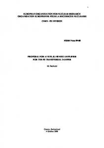
Among the engineers who began to apply technically appropriate and elegant solutions to reinforced concrete constructions, Robert Maillart, Edouardo Torroja, Eugéne Freyssinet, Pier Luigi Nervi, and Felix Candela were notable pioneers. It is possible to say that especially Nervi and Candela had a deep interest in natural structures. Nervi (1891-1979) had an ability to derive beauty from the natural forms and from the selection of the right materials and techniques. In his opinion “the process of creating form is identical, whether it is the work of technicians or of artists: the principle that is, whereby the beauty of a structure, for example, is not just the outcome of calculations, but of an intuition as to what calculations to use, or with which it is to be identified” (Lampugnani, 1989).
Figure 2.3 Exhibition building in Turin and Small Stadium in Rome (plan of the dome and 200 times magnified Radiolarian) (Source: Mainstone,1998 ) His Exhibition Building in Turin shows that he achieved in obtaining “strength through form” in buildings, which was the aim of his studies and experiments. The enormous building consists in effect of a single roof structure, made up of undulating prefabricated units (Figure 2.3). It is arguable that light vaults and domes were the most important architectural innovations of the 1950s, most of which were contributions of engineers like Spanish architect Felix Candela, who drew on his experience as a builder to construct the thinnest conceivable shell with the design of a roof in hyperbolic paraboloids only 15 mm thick (Cosmic Ray 21
Building 1951, Mexico City). His method of shell construction is notable for its extreme economy of material. He designed a variety of structures that used hyperbolic paraboloids, or saddle-shaped shells, which were stiffer and easier to build than other shell constructions. Like Nervi, Candela claimed to have been guided less by exact calculations than by an intuitive feeling “in the manner of the old master-builders of cathedrals”. This intuition was based on his knowledge of materials and stresses, accumulated from each of his projects. In 1961 Frei Otto met biologist and anthropologist J. G. Helmcke, and together they founded the research group Biology and Nature to examine the many and varied biomorphous constructions of algae, which became an important inspiration in Otto‟s designs (Gössel & Leuthaser, 1991). With similar ideas, Otto experimented on many natural objects at the Institute for Lightweight Structures, founded in 1964 at the University of Stuttgart, and developed new constructions through analogy with natural models. He concentrated his attention on the analysis of biological phenomena, developing his exploration and analysis of lightweight structures in nature. His research was focused on the optimized features of structural forms in nature and lightweight construction (Drew, 1976). His experiments with suspended chains were to find shapes for a long-span suspended roof, stabilized by its own weight without pre-tension. Soap film experiments to produce minimal surfaces were performed with an understanding of natural phenomena, with the understanding that a soap film always contracts to the smallest surface possible. The concept of soap film minimal surfaces was then applied to the tent structures (Otto, 1995). Many features of his cable-net roof experiments are inspired from spider‟s webs. He concentrated on how to achieve more with less, that is, less material and less effort. He developed innovative structures of extreme lightness coupled with extreme strength, making optimum use of new materials such as thin cables of high-strength steel or thin membranes of synthetic fabric (Figure 2.4).
22
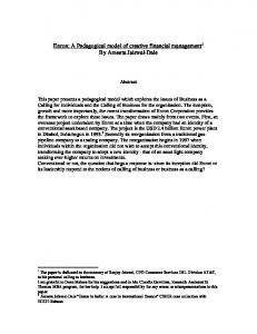
Figure 2.4 Studies from Frei Otto (Source: Otto, 1995) The works of D‟Arcy Thomson and Frei Otto were used as references for nature‟s strategies in achieving strength in rigid tissue forms. Robert Le Ricolais‟ documentation of his experimental research workshop at the University of Pennsylvania clarified how analogical thinking advanced structural ingenuity in the design process. Fred Angerer‟s investigation into surface structures demonstrated that conceptual analogy could be linked with technical strategy in the structural articulation of load bearing surface forms. He explained how to explore the concept of minimum material for maximum strength and the relationship of geometric patterns to highly effective forms that resist compression and bending forces like in natural ones (Otto, 1995). In his 1969 book “Architecture 2000-Predictions and Methods”, Charles Jencks predicted that the influence of major biological inventions in 1980s and 1990s would result in the most significant architectural movement of this century - the Biomorphic School (Jencks, 1971). He wrote that the Biomorphic School had already had a long history reaching its zenith a the beginning of the 20th century with the work of Antoni Gaudi and Frank Lloyd Wright, and later gaining in strength with the work of Soleri Goff, Kiesler, Scharoun, the Metabolists, Johansen, Rodilla, O‟Gorman, Couélle, Hausermann, Bloc, Katavolos, Guedes, Doernach, and at times Le Corbusier. According to Jencks, the Biomorphic School was already a strong movement (Figure 2.5).
23
Figure 2.5 Table of architectural concepts by Jencks (Source: Jencks, 1971) Taking individual examples from recent years, Renzo Piano‟s design, the Jean-Marie Tjibaou Cultural Center, exhibits a harmony with nature by using local materials and combining traditional techniques with technology. This building has external forms that resemble vegetables growing from the ground. They are framed by curving laminated pine ribs, which are secured together using stainless-steel rods, and have bamboo and bark slats on the outside. The structures provide shade for the spaces below and guide wind and convection. They have a lattice-like appearance which brings to mind plant tissue. Likewise, the Japanese capacity for combining high technology with nature and tradition can be seen perhaps at its most extreme in the Kansai International Airport and Passenger Terminal Building in Osaka, Japan. “In this prize-winning project, in December 1988 in an international competition, Renzo Piano with his partner Noriaki Okabe seems to have found the perfect mean for his noted ability to apply the laws and forms of nature to sophisticated high-tech systems.” (Buchanan, 2005) A widely-used structure of nature is the “tree”, which can be found in numerous examples from earliest periods of architecture. Norman Foster‟s terminal building at Stansted Airport is a steel-structured building with a roof composed out of a series of shallow, partly-glazed domes supported by a forest of tree-like structures (Foster and Partners, 2005). The columns are generated by the functional requirements of the terminal and the need to 24
provide maximum flexibility at the passenger floor level. The tree-like structures are comprised of clusters of four interconnected tubular steel columns. Similarly, Stuttgart Airport, designed by von Gerkan and Marg, completed within weeks of Stansted Airport, has a huge sloping-roof supported by 12 very tree-like steel structures, in which the loads can be seen to be descending through an elaborate hierarchy, from twigs to branches to trunks, all fundamentally in compression (von Gerkan, and Marg, 2007). The examples included in this part of the study reveal the influence of nature in 20 th century architectural designs explicitly, and are accepted as benchmark examples of their era. Yet it is possible to multiply the number of examples yielding the influence of nature, either in the design or process, or in the final artifact. It is unavoidable that when nature is imitated there will be differences of scale, function, and internal structure, especially when the natural form is a living organism. The most significant difference between them is the differences between the processes of construction and natural growth (Mainstone, 2001). These differences have had a marked effect on the development of architectural forms. Even though the scale, function, and process may be different in nature, design constraints and objectives are very similar: functionality, optimization, and cost effectiveness are targeted to co-exist in man-made products. Therefore, it is no surprise that mankind has always admired biological structures and has often been inspired, not only by their aesthetic attributes, but also by their design and structural quality and efficiency 2.2.3 Inspirations from Nature in Contemporary Architecture Biomimesis is a term used to describe the act of developing different methodologies inspired by nature to innovate and provide solutions in various disciplines. Until now, Biomimesis in architecture has been restricted in terms of understanding and usage, limited to being either “a form finding process” inspired by countless forms, colors and details from nature, or as a way to provide solutions for sustainable/green designs. As is evident in Koelman‟s (2003) comments on the matter, Biomimicry can be applied to buildings in three fundamental ways; “by making stronger, tougher, self-assembling, and 25
with self-healing materials; by using natural processes and forces to accomplish some comfort requirements of buildings such as heating and cooling; and finally by providing resources, rather than draining them, by using/applying the principles of Biomimesis for zero waste and co-evolution”. Those approaches are actually coupled well with the declaration of Benyus. In this regard, as an example the natural ventilation system of the Eastgate building by Arup in Harare, Zimbabwe drew inspiration from African termite towers (Figure 2.6). Termites build their homes in the desert in extreme temperatures, and yet manage to keep the interior of the building cool and clean. The mounds are cooled in a very clever way that uses the stable low temperatures under the ground. According to Koelman (2002), from a whole-system perspective, the African termite mound might be the supreme example of advanced animal architecture, incorporating exquisite solutions to design problems (structural strength, elemental protection, ventilation, humidity control, etc.) that architects also face. So far, at least one building has been highly successful in mimicking this sophisticated ventilation system. From this perspective the Eastgate building uses the termites‟ nests as a source for innovation in the building‟s HVAC design to keep the building cool, even on the hottest days. Using nature-inspired designs for the ventilation and heating/cooling of buildings instead of high energy-consuming HVAC systems, as in this example, indicate potential for further innovative design solutions for more environmentally friendly, and yet efficient, building systems.
Figure 2.6 Section and view from the African termite towers and the Eastgate building by 26
Arup in Harare, Zimbabwe. (Source: http:/www.arup.com/expertise/casestudy.cfm studyid=6) Another example inspired from this system is the Ionica Building, Cambridge, designed by the RH Partnership. The designers of this building admit that they took lessons from the humble termite regarding their heating and ventilation properties. Natural resources are used to regulate the temperature within the building, and as a result running costs have been reduced by 45% 6. There are several other architectural designs which are acknowledged as Biomimetic buildings due to their sustainable solutions, whether related to their design or to the building systems that they contain. For instance, in all of its five areas, as specified in the in the project, the Eden Project, Cornwall, UK designed by Grimshaw is accepted as Biomimetic. Its aim is to promote the understanding and responsible management of the vital relationship between plants, people, and resources, leading towards a sustainable future for all (Grimshaw, 1993) (Figure 2.7). In the same way, the Kalundborg Industrial Symbiosis project in Denmark is another Biomimetic approach. Symbiosis means a coexistence between diverse organisms in which each may benefit from the other. In this context, the term is applied to the industrial cooperation taking place in Kalundborg between a number of companies and the Kalundborg Municipality, all of which exploit each other‟s residual or by-products. All the above projects are considered to be environmentally and financially sustainable. Finally, having a double skinned façade, Plantation Place, London, by Arup has a blind system which responds locally to the sun, keeping it in or out only where and when absolutely necessary. It also has an air filtration system which works rather like the human lungs. Polluted air is kept out at ground level, while cleaner air is drawn in from higher up and pumped through the building.
6
http://www.battlemccarthy.demon.co.uk/projects/ionica.html
27
Figure 2.7 View from Eden Project (Source: http://www.eden-project.co.uk)
Biomimesis can also be applied to buildings in terms of new sustainable materials. The need for cleaner buildings by maintaining surface coatings for as long as possible without polluting the environment with chemicals in paints and dust and dirt provoked Prof. Dr. Wilhelm Barthlott from the University in Bonn, Germany, to ask "How does nature clean surfaces?" He focused on this question and examined the surface of the leaf for clues. His research team found that nature has a way of structuring surfaces with self-cleaning properties, especially the “lotus” plant, which lives in muddy environments and has a selfcleaning leaf (Koch, 2004). This insight has given rise to a new type of building façade with a texture that has properties comparable to the lotus leaf: water droplets from the rain roll off the surface, automatically removing dirt as they wash over. A German company is manufacturing such a product, called Lotusan 7 as an architectural material. To sum up, in the 1970‟s Professor Barthlott‟s discovery on the self-cleaning properties of lotus leaf, followed by studies into its nanostructure and the application of its design onto glass, plastic and other materials to ensure long-term resistance to staining from environmental effects, such as pollutants in air, is a very remarkable example of Biomimetic design. (Figure 2.8)
7
http://www.lotus-effekt.de/en/lotus_effect_html.html
28
Figure 2.8 Lotus effect (Source: www.lotusan.de) Lastly, an important field of application is the design of kinematic structures, which is a subject of interest of the new century, for which there are clues and answers in nature as well (Arslan Selçuk et.al, 2005a). Zuk, one of the leading figures of kinematic design in architecture, asserts that life itself has an inherited motion, as in a single cell to the most complex organisms, from subatomic particles to galaxies. He goes on to state “…when motion ceases, life ceases” (Zuk, 1970). All living creatures in nature have the ability to move in order to live. For instance, animals move to migrate and hunt, or plants move according to climatic conditions, and all have particular mechanisms of their own for motion. Such propositions can be extended when the concept of Biomimesis is welldefined in an architectural context and thus allow design solutions having roots in nature with new potentials. In concluding, as it can be seen from the following diagram (Table 2.2) that nature has always been a stimulating source on architecture and left clear traces throughout the history. Nowadays as it is seen from the same mapping, when the concept of “Biomimesis in architecture” is considered, the term is generally interchangeable with the term “sustainability in architecture”. It is also possible to claim that increased Biomimetic studies and enhancing Biomimetic way of thinking would result in a drastic change in architecture. This respectful imitation is a radically new approach, a revolution. For the near future, unlike the Industrial Revolution, the Biomimetic Revolution will introduce an era based not on what we can extract from nature, but on what we can learn from it as a mentor. 29
Biomimesis can serve architecture with its all potential in a more extended way. Biomimesis can propose new and innovative solutions for forms, structural systems, and even systems for environmentally friendly kinematic/static/deployable structures, as can be observed in structures/forms in nature with the help of a systematic and methodologies to be developed specific for architectural design. Current examples in architecture, related with Biomimetic developments, are still quite individual and sporadic due to the lack of systematic designing criteria for architecture and that disables being a discipline as in other research and implementation areas like engineering, medicine and agriculture. Architects, who want to be aware of “next technological wave” arising from advances in technology and science in consequence of observation of nature and its phenomena, and who want to design such buildings in accordance with those advances and reflect the features of the era to which they belong to, have the possibility to study the “nature-architecture” relationship using methodologies provided by the new discipline of Biomimesis.
30
Table 2.2 Changing paradigm in nature architecture relationship
31
CHAPTER 3 THEORIES AND POSTULATE Today, while “what Biomimesis is and is not” is continuously brought to question; man is still learning to conceive nature as a source for further knowledge. Some disciplines, like robotics, biomechanics, chemistry, electronics etc., have been developing a systematic and methodologies for studying nature and its phenomena to find innovative solutions. It is shown in the previous chapter that drawing inspiration and learning from nature, i.e. Biomimesis, has always been part of architectural design theory, revealing itself in the forms, structures, patterns, and colors in the search of lightness and material qualities which are found in nature. Yet, when examples in architecture are studied within the realm of Biomimesis, it can be seen that most of these “end-products” of such a process have, in general, failed to go beyond form finding processes, and many other potentials that can be brought into design using a Biomimetic approach have been ignored. Recently, it has been observed that all living things in nature have the ability to fit form to function efficiently through structure and material, i.e. form, function, and materials come into existence simultaneously. This process can be considered as “multi-dimensionality in the natural world”. In this process every organism in nature avoids excesses and “overbuilding”, gains maximum efficiency with minimum material and energy, recycles and finds a use for everything, requires local expertise, runs on the sun and other natural sources of energy, and uses only the energy and resources that it needs (Benyus, 1997). These aspects that make the natural world sustainable are quite different from what human beings have experienced in their structures up until now. In man made products, contrary to the multi-dimensional properties of the natural world, the conventional manufacturing processes in man-made structures are very “linear”. In other words, man made structures come into being following the rigid order of a design process, starting from the design of form, followed by function, structure, material, manufacture, mapping of materials, and finally the end product. In this study it is aimed to criticize the limited use of Biomimesis in architecture by considering developments in science and technology, the conveying of several other 32
disciplines and so on. Although most of the studies in disciplines other than architecture have developed specific methodologies to embed Biomimetic elements into their research areas in an objective way, architecture is still in its infancy, experiencing only “formcreation processes”, mostly conceived as the inclusion of the use of computers and solid modeling interfaces as design tools. However, examples from different disciplines have proved that the use of Biomimesis has more potential, and can contribute to reexperiencing and taking influence from the forms-structures-materials etc. observed in nature, providing not only flexibility in the creation of forms but also in functions and efficiencies in fulfilling their tasks. Hence, Biomimesis can be a new interface for learning, having its own systematic with objective design parameters to propose new design paradigms for architecture. For this purpose, in this study of the realm of Biomimesis, the most common abstracted structures used in architecture are explored. Forms are to be classified in an analogous way to the structures found in nature. Classified forms and structures are studied not only for their formal resemblance, but also their form possibilities and structural properties, providing required static and dynamic stabilities and strengths accompanied by lightweight and minimized energy consumption. 3.1 Biomimesis in Architecture The examples presented in the previous chapter, which are related either with the imitation of nature through forms for new challenging architectural designs, or through their functions for sustainable solutions, may not be adequate to give clues of how Biomimesis can be involved in the architectural design process, as has been experienced in other disciplines. In other disciplines, like mechanical and material engineering, robotics and medicine, Biomimesis has been successfully implemented with its own systematic and rules. Hence, in this dissertation, a “system design” in architecture is proposed, aiming to show all the possibilities of Biomimesis in architecture while continuing to learn from nature. The complex generation process of the form-structure-function trilogy to fulfill the “task of being existent”, as it is observed in nature, should be studied more in order to allow implementation with all its potentials in architectural design. Biomimesis can then be 33
considered as a new “tool” in this exploration process through its systematic ways of analysis and synthesis, allowing development of methodologies peculiar to the field of interest. Hence it is possible to claim that Biomimesis in architecture is a new platform/interface in which architects not only imitate or are inspired by nature, but learn from it to provide efficient designs that include the best features of their studies. After all the discussions above, it can be concluded that to understand the potentials of “Biomimesis in architecture” there is an apparent need to develop a methodology for architects. Architects should question natural processes regarding the multi-dimensionality of the process of their creation and evolution accordingly, starting from the abstractions of structures found in nature. Therefore, in the following section, firstly structures found in nature are classified, animate and inanimate structures in nature are discussed, and potential structural solutions are revealed from an architectural point of view. Then, the most common architectural structures that have been inspired from natural forms and structures are classified to understand to what extent they have affected contemporary architecture. 3.1.2
Biomimesis
in
Architecture:
Relationship
among
Nature-
Structure-
Architecture While the scale, function, and processes observed in nature are different to those found in architecture, the constraints and objectives (functionality, optimization, and cost effectiveness) are very similar. Therefore, it is no surprise that mankind has always admired biological structures and has often been inspired by them, not only in their aesthetic attributes but also in their engineering and design qualities and efficiencies. When the interaction between nature and architecture is studied, it can easily be seen that the interventions between what architects design and what exists in nature are very complicated, ranging from materials to construction techniques, from structural systems to aesthetics. In this section, firstly the structures inspired by those in nature are categorized according to their animate and inanimate nature, and again according to their visual/formal similarities. Following this categorization, examples are presented to illustrate the similarities between natural and man-made structures using a number of benchmark examples from the history of architecture. 34
3.1.2.1 Classification of Structures in Nature
Nature exhibits a diverse variety of structures, and generally the form and visual qualities of nature‟s animate or inanimate forms have evolved due to internal and external environmental forces, and static and dynamic loadings. This complex formation process and duality of form and structure make it difficult to compare man-made structures with those in nature. Hence, it is necessary to establish criteria for further analysis of manmade designs and forms observed in nature in a systematic way. In the next section, some categories are presented regarding the structural behavior and the formal/visual characteristics of animate and inanimate formations in nature, and major structural systems observed in many architectural designs are compared within the bounds of these categories. In this categorization, structures produced by animals (Hansell, 2005) can also be included within the animate nature.
Figure3.1 Examples from inanimate nature (Source: Otto, 1995)
Objects in non-living nature - simple atoms and molecules, crystals, rocks, mountains and waters, stars and galaxies etc. - constitute a set of characteristic forms and structural properties (Noel, 1978). The processes of formation shape their final forms, by which the structural system is shaped with material properties, and static and the dynamic internal and external loadings of the environment in which they should stand, e.g. by the laws of the physical universe. The analysis of structures in non-living nature show that in their development only a limited number of formation processes take place: the accumulation of masses, the movement of large masses, the flow of liquids and gases, and the 35
solidification of matter into solid bodies. Yet those inanimate structures have extremely long life spans when compared with the life span of any animated form. One of the important non living nature examples in architecture can be considered as the polyhedrons (Platonic Solids) inspired from stars, crystal like structures in prisms, antiprisms, geodesic domes, and folded plate structures tensegrity structures, as well as space frames applications. Animals, plants, and microorganisms are the “living structures” found in nature. They are able to assimilate and transmit forces with little expenditure of material and energy, even in their short period of existence. It can easily be seen that the world of animate nature is absolutely diverse, mobile, and mutable, and is diverse when compared with inanimate nature. Another important categorization of the structures in nature can be introduced in relation to load bearing capacities, as in the case of man-made structures.
Figure3.2 Images from animate nature It is observed that one-dimensional natural structures are mostly lightweight elements, such like tension-stressed fibers, hairs, sinews, muscles; and compression and bendingstressed stalks, trunks, branches, bird feathers, and bones. Membranes of cells, skins, intestines, and spider webs can be considered as two-dimensional structures that are resistant to tension, exhibiting membrane or shell characteristics that are able to transmit forces through their surfaces. Structures composed of tension and compression-stressed elements, such as the wings of insects, bats, and birds etc. can be considered as twodimensional, however most of the structures in living nature are three-dimensional. Many compression and pressure stressed structures, like vertebral bones and compression and 36
bending-resistant skeleton systems of trees and bushes, the spongiosa inside bone, and the three-dimensional skeletons of radiolarian, can also be included in this categorization. The bodies of many animals consisting of tension, compression, and bending-resistant elements are also three-dimensional. All structures used in architecture belong to one of these categories, depending on the forces that they are subjected to. In a building, the structural elements can vary from onedimensional tension or compression members, to plates and shells to support a diverse variety of internal and external loads, as is the case with structures in nature. Any structure in nature and any man-made structure should withstand similar forces and loads. Thus, it is very natural to draw inspiration from nature in the design of new innovative structures. 3.1.2.2 General Taxonomy of Architectural Structures Inspired by Nature Developments in science alter the way the process of life is perceived in physical nature. An analytical approach to natural and cultural phenomena emphasizes the basic characteristics of the modern age. Nietzsche says that “scientific method distinguishes the nineteenth century”. Therefore, an analytical approach to nature is achieved through “scientific method.” Method means the type of researching the objects within the limits of objective research areas. Scientific method is a body of techniques for investigating phenomena and acquiring new knowledge, as well as for correcting and integrating previous knowledge. It is based on gathering observable, empirical and measurable evidence subject to specific principles of reasoning, the collection of data through observation and experimentation, and the formulation and testing of hypotheses 8. When it is possible to test and interpret the world in nature by numbers, then it may be possible to understand the process of structuring and use those ideas in nature to the advantage of mankind, which is the basic aim of Biomimetic researchers. In architectural discourse the break between the ancients and moderns occurred in the 19 th century, when the question being raise by architects changed from “what” to “how”, that is from the object to the process. This change allowed researchers to discover new architectural and structural solutions derived from the observations of the natural environment.
8
http://en.wikipedia.org/wiki/Scientific_method#_note-0
37
Following these researches, a new formal understanding and aesthetic of the architectural entity emerged in the 20th century. Structural aesthetics changed with the new basic principles. Gropius, the founder of the pioneers this theme, Bauhaus, claims, "…as history shows, the concept of beauty has changed along with progress in thinking and technique.” (Hartoonian, 1994). A similar statement is made by Nervi "…every improvement in the functional and technical efficiency of a product brings about an improvement in its aesthetic quality (Holgate, 1986). For Nervi the result is a truthful style, and its characteristics are structural essence, a necessary absence of decoration, and a purity of line and shape. If a building is correctly designed in its structure, its beauty shines from the correctness of the structure. It is not a matter of which material you use, but how you use it. It is possible to claim that innovation derived from technology, new modes of calculations, computation, and new theories have been developed by the architect‟s intuition. Developments of structural design in the Modern Movement employ several theories from different disciplines, like mechanics, pure mathematics, civil engineering, the use of new materials, and the architect‟s intent. Knowledge of building technology changes from being a craft to a scientifically-designed entity, and there is a tendency to use mass produced rather than natural materials. Knowledge of materials also raises an opportunity to explore more challenging and innovative structures. In this respect, several structural systems that have been developed allow spans of larger distances than ever before. It is important to mention that these structures show the similarities between structures in nature and manmade structures. In this study, structures are classified into five main categories, namely, tree-like structures, web-like structures, shell-like structures, skeleton-like structures and pneumatic structures. Pioneering examples of each category belonging to different periods of architectural history are presented. Through an analysis of these examples the visual similarities in man-made structures and structures in nature are discussed in the context of Biomimesis.
38
3.1.1.2.1 Tree -Like Structures In the tree, nature has presented the concept of growth and multiplication in which the sequence of trunk, branch, leaflets, and leaves exemplify patterns which are very similar to those governing architectural orders. In the categorization of structures according to their formal/visual characteristics rather than their load carrying capacity, the first category appears to be tree-like structures. Throughout history, trees have been significant for mankind, being the preferred choice in the provision of many needs, from heating to housing. Observations of tree-like structures led man to gain knowledge in new constructional methods and structural systems to satisfy their needs. When historical architecture is examined, a very deep and developed intuitive knowledge of construction becomes visible. According to Portoghesi, the tree has taught man the concept of growth and multiplication, since ramification lies at the very heart of its nature. The branched support tree-like structure can be first observed in the ribs of the Gothic style, while today tree-like structures in architecture are mostly three-dimensional support systems, which have been used increasingly in steel, wood, and concrete buildings. One of the oldest examples of a tree-like structure is the Eddystone Lighthouse, Southwest of Plymouth (1759) by John Smeaton. Smeaton‟s model was based on an English oak tree, which he considered as having the best configuration to resist the forces of nature (Addis, 2001). Similarly, Antonio Gaudi, who practically never journeyed anywhere, drew his inspiration from his ability to observe and reuse the countless details offered by nature. When one enters the crypt of Sagra da Familia in Barcelona, the four inclined basalt columns standing out give the sensation of an organic and natural structure, like trees in a forest. In the 1970s, great interest was given to architectural structures derived from the ramification concept in nature. Frei Otto studied the “minimum path system” to investigate a form for compression-loaded ceiling and roofing (Roland, 1970). Otto claims that the fan structure (a) as used in timber and steel building can be addressed as a materialized direct path network. The branched fan construction (b) is more effective in many cases as the buckling lengths of the compression members are reduced; while the tree branched structure (c) is a materialized path network with minimum detours, needing a relatively small amount of material and with a load bearing capacity that can be increased by thin 39
branches (d) Figure 3.3 (Otto, 1995). Several structures were constructed by Otto following this concept, and by later architects following his design principles.
Figure 3.3 Branching theory of Frei Otto (Source: Otto 1995) In today‟s architecture, tree-like columns are very common due to developments in the steel industry and CAD-CAM technologies. BCE Place (1987) was designed as a mixeduse complex in Toronto by Santiago Calatrava. The structure of the complex comprises eight inwardly-inclined steel supports bifurcated upward, eventually meeting to form pointed parabolic vaults spanning 14 meters across the interior space. Over a 30-by-3meter regular plan, tree-like structures rise and support nine intersecting barrel vaults, creating a “forest” effect (Tzonis, 1999). Rather than resorting to the imitation of these precedents, however, Calatrava reinterprets them as “forests” of structural “trees.” This forest effect in Calatrava‟s designs is very common, and can be found in the Bauschanzli Restaurant, Zurich (1988), the Cathedral of St. John Divine, New York (1991), Oriente Station, Lisbon (1993-98), and the Reina Sofia National Museum of Art, Madrid (1999).
Figure 3.4 Examples from Calatrava‟s tree-like structures BCE Place, Bauschanzli Restaurant Oriente Station (Source: Zardini, 1996) 40
Figure 3.5 Examples from contemporary tree-like structures Stuttgart Airport Passenger Terminal (Von Gerkan, 2007), Stansted Terminal (Foster and Partners, 2005) The roof of the Stuttgart Airport Passenger Terminal, Germany (1996), designed by Meinhard von Gerkan, is among the contemporary examples of tree-like structures. The huge sloping roof is supported by 12 very tree-like steel structures, in which the loads can be seen to be descending through an elaborate hierarchy, from twigs to branches to trunks, all fundamentally in compression. More directly, the construction of the terminal roof is based on the structure of a tree, thus providing an unmistakable and individual feature for Stuttgart Airport (Figure 3.5). There are a vast number of examples of tree-like structures that can be found in the history of architecture, all of which exhibit the main architectural and technological characteristics of their period. Besides those examples there are many other progressive architects who have been influenced by trees in their designs, whether consciously or not. 3.1.1.2.2 Skeleton-Like Structures When most animals are examined, every bone of the skeleton, and the skeletal system itself, show how nature has formed a sophisticated, lightweight, and rigid structure that is perfectly suited for kinetic design. Since the main structural elements of buildings are 41
based on the spine, as is the case in animals, it seems obvious that a further lessdominant structural element should be based upon the ribs. In nature the spine and ribs work in conjunction with one another to provide support and protection. This idea seems plausible for buildings as well. Ribs provide support for the roof and create enclosure in the form of a building. While designing the famous Eiffel Tower, Maurice Koechlin, assistant to the architect, was inspired by the femur, the lightest and strongest bone in the human body, with self-ventilation properties due to the porosity of the bone material, as shown in Figure 3.6. Buildings designed and constructed similar to this bone optimize the construction material, and also provide firmness and flexibility in the skeleton of the construction (Williams,2003). Again, Gaudi, in Casa Battlo (Barcelona 1905-1907), showed natural and organic forms which were no longer ornaments superimposed on the building, but constituted essential structural elements, as in the case of bone-shaped columns shown in Figure 3.6. As a contemporary example, Nicholas Grimshaw‟s addition to Waterloo Station, which can be likened to the human hand, can be presented (Grimshaw, 1993). The cupped “hand” reaches across the track to make an enclosure of the space. Study of the conceptual sketch of the hand can easily reveal the influence of the skeletal structure on the structure of the building.
Figure3.6 Images from skeleton-like structures Eiffel tower and femur (Source: Williams, 2003), Casa Battlo (Source: Masso, 1999), Waterloo Station (Source: Grimshaw, 1993) Santiago Calatrava has also used features of an animal shapes and skeletal structures in the design of many of his bridge and building projects (Williams, 2003 Sharp, 1994). He 42
understands how a body varies in order to accommodate its various parts and forces through identical rib-like pieces, which are less expensive to manufacture and yet have a high capacity to carry uniformly distributed loads when they are employed in man-made structures. Calatrava could possibly be considered the master of today‟s skeleton-like architecture. 3.1.1.2.3 Web-Like Structures In the categorization of structures found in nature, web-like structures have another importance in addition to their load carrying capacity that arises from their silk-like quality. Spider silk is stronger and more elastic than Kevlar, the strongest man-made fiber (Shear et al, 1989). Web-like structures exhibit membrane characteristic in their load bearing features. Moreover, their load carrying capacity is extremely high, and yet the structure itself is lightweight. Tents, which are basically man-made membrane structures, can be considered similar to those web-like structures in nature (Beukers, 1990). Drawing influence from the tents of indigenous people of different regions, a very early example of large-scale use of a membrane-covered tensile structure can be seen in the truss-roofed exhibition pavilions constructed for the Nizhny Novgorod Fair of 1896 by Vladimir Shukhov, and the Sidney Myer Music Bowl, constructed in 1958 (Kronenburg, 1996). In the 1960s, Frei Otto, who studied the similarities between tents and web structures, was the pioneer architect of tensile construction. He improved his new concepts by focusing his investigations on one of the principal forces encountered in a structural system - tensile stresses. The modern tent is principally based on Otto‟s studies and designs and can be compared to a spider‟s web in the way it uses strength and grace together. It is a perfect example of using the minimum amount of material to cover a vast area. Traditional tents were revived by Otto as a leading prototype for lightweight adaptable buildings (Otto, 1995).
43
Figure 3.7 Web-like structures in nature (Source: http://www.hainaultforest.co.uk) and architecture (Source: http://www.panoramio.com/photo/9972384) Innovative structures with extreme lightness have been developed by Otto throughout his studies. Since the 1970s, web like structures have been championed by designers and engineers such as Ove Arup, Buro Happold, Eero Saarinen, Horst Berger, Matthew Nowicki, Jorg Schlaich, the duo of Nicholas Goldsmith & Todd Dalland at FTL Design & Engineering Studio, and David Geiger (Robbin, 1996). Steady technological progress has increased the popularity of fabric-roofed structures. The low-weight materials make construction easier and cheaper than conventional methods, especially when large open spaces have to be covered.
3.1.1.2.4 Pneumatic Structures Pneumatic structures, which occur both in inanimate and animate nature, can easily be found in a variety of forms of animate nature, plants, and animals in various life processes and conditions. Pneumatic structures have been developed and built up through countless variations of a single construction principle, namely, the principle of the “Pneu”, which is a system in which a tension-resistant, flexible envelope surrounds a filling (Dent, 1972) The envelope and the filling together form a load-bearing structure.
44
Figure 3.8 Montgolfier Brothers‟ hot air balloon (1783) (Herzog, 1977), Jacques Charles hydrogen balloon (1783) (Herzog, 1977), Santos-Dumont No 1 Dirigible (1898). The first experiments with pneumatic structures were undertaken during the development of hot air balloons. Brazilian priest Bartolomeu de Gusmão conducted a pioneering experiment as early as 1709 in Lisbon. At the end of the 18 th century the Montgolfier brothers built an 11 meter diameter hot air balloon made from linen and paper. Jaques A. C. Charles, the father of the Zeppelins, began construction of the first hydrogen balloon, a large rigid dirigible, at the end of 19 th century (Herzog, 1977; Forster, 1994). From an architectural point of view, the best of our present knowledge starts with English motorcar manufacturer Frederick William Lanchester, who first recorded the idea of supporting tents through internal air pressure in 1917. During Word War II, and following the invention of nylon, the idea started to be used by the military for emergency shelters (Topham, 2002). In the following years, pneumatic constructions and their use of air as a supporting medium became a part of architectural language. The study of air bubbles formed in liquids is undoubtedly nature‟s most relevant precedent in the design of pneumatic building construction, and this approach was a starting point for Frei Otto. Systematic research and development of the form, finding processes of technical pneumatic constructions by Otto and his team resulted in progress in the development of new structural systems having roots in pneumatic forms in nature, allowing the construction of many innovative building forms. Through the IASS Pneumatic Colloquium (University of Stuttgart, 1967) and several publications and designs, Otto broadened the landscape, not only of pneumatics, but of tension structures in general. Pneumatics was also part of the repertoire of Richard 45
Buckminster Fuller, whose proposal of a pneumatic dome to cover New York (Figure 6) is a famous example of Utopian pneumatic architecture (Baldwin, 1996). At the end of the 1960s, the Paris group Utopie, which included architecture students Jean Aubert, JeanPaul Jungmann, and Antoine Stinco, and sociologist Jean Baudrillard, among others, formulated criticisms on architecture, urbanism and the daily life of French society. They were also influenced by the Archigram Manifesto and reinterpreted the aesthetic of pneumatic structures, using them as a form of social expression related to ephemerality and mobility, in contrast to the inertia of the postwar European society (Dessauce, 1999). The use of pneumatic structures, such as the Fuji and American Pavilions in exhibitions, reached a peak at Expo „70 in Osaka, Japan, when they were widely adopted due to the poor quality of the soil and high seismicity of the region. Another interesting example is provided by the Floating Theater, which was realized by the same team that produced the Fuji Pavilion. The structure was composed of three inflated tubes, highly pressurized and connected by a single layer membrane, with the inner space kept under a negative pressure, thus providing a rare case of an aspirated pneumatic structure (Wilkinson, 1996). David Geiger developed several projects employing cable reinforced, insufflated membranes for sports stadiums in the United States and Canada from 1974 to 1984. The largest of these stadiums are the Pontiac Silverdome in Michigan (1975), the Vancouver Amphitheater (1983) and the Minneapolis Metrodome (1982), all of which cover more than 40,000m2 with capacities of more than 60,000 seats (Foster, 1994). Likewise, in the 1990s this structural system was very popular for large-span roofing, such as in the Big-Egg Dome in Tokyo (Figure 3.9), the Expo‟ 92 German Pavilion in Seville, and the Nimes Roman Arena in Rome.
46
Figure3.9 Tokyo Big-Egg Dome (Source: Forster, 1994)
Figure 3.10 Archipelago, by Architects of Air (Source; Topham, 2002) In today‟s architecture, pneumatics are frequently used in smaller and ephemeral/ temporary buildings, more for aesthetic than economic reasons, since their futuristic and revolutionary appearance usually provokes fascination among observers and users. The pneumatics return is even more impressive in the field of object design, as there are fewer constraints in the exploration of new shapes, especially with the aid of the modern computerized design tools and the availability of high tech materials. Eloquent examples are given by the colorful and organic pavilions of Maurice Agis or the Architects of the Air and Buildair offices. (Figure 3.10)
47
3.1.1.2.5 Shell-Like Structures Shells are among the most common and most efficient structural elements in nature and technology because of their high resistance, minimum material, large spanning capacities and sheltering characteristics. Examples of shells in the morphology of nature are particularly abundant (Melaragno, 1991). Many great artists were inspired by the beauty, diversity and design of the shell, that they incorporated them into their masterpieces. Architecture has been profoundly influenced by the geometry and sheltering capacity of these 'natural wonders' done by snails, clams, scallops, and other marine mollusks. Many scientists could not avoid themselves to study of shell shapes from mathematical and geometrical point of views.
Figure 3.11 Shell examples from nature and architecture (Source: Melaragno,1991, Senosiain, 2003, Chiat, 2004) The discovery of cement made possible the realization of new architectural designs using thin shells in structural systems. Moreover, the advent of concrete as a new building material at the beginning of the 20 th century strongly influenced the conventional way of construction and the design of new domes. In the 1920s, the first examples of reinforced concrete shells were introduced by Franz Dischinger and Walter Bauersfeld, evoking a comparison of their domes with eggshells. The technology developed by Dischinger, Finsterwalder, and Bauersfeld in the 1930‟s was compatible with single-arched structures, and following this, further developments in the analysis of these forms and their manufacturing processes made possible the building of more complicated forms, such as double-arched saddles (Gössel & Leuthauser, 1991). Later, many other engineers and architects, such as Robert Maillart, Edouardo Torroja, Eugéne Freyssinet, Pier Luigi Nervi, 48
and Felix Candela were to design and apply technically appropriate and elegant solutions to reinforced concrete constructions. Among them, Nervi and Candela brought some solutions to their designs that were inspired by structures in nature. To conclude, as seen from the taxonomic diagrams (Table2.2 and Table 3.1) and the examples chosen from different periods in architectural history, man-made structures are deeply influenced by structures in nature. Many progressive architects and engineers have been inspired by nature – by both animate organisms and inanimate structures. This inspiration led some architects, such as Otto, Fuller, and Candela, to establish institutes to research natural structures and patterns. They contributed to architectural design and the development of new structures based on structures in nature. Apart from these names, the general tendency of the “nature-architecture relationship” stayed only as a source of inspiration for architects. Examples from these two approaches reveal that nature has always been a part of architectural design, either implicitly or explicitly, and architects have found clues in nature for new designs and technologies. Hence, in the world of architecture nature has and will always be a source for the next generation of designs, as has been the case in the past. Using nature as a source of stimulation in architectural design was given several names in different architectural periods. Nowadays, this concept is discussed within the realm of “Biomimesis in architecture”. This terminology implies that naturearchitecture interaction can go beyond the “form finding process” and can be a “learning interface”, having its own systematic with objective design parameters - as in many other disciplines - changing design the paradigms for architecture. It is widely accepted that Biomimesis has more potential and can contribute to (re)experience and the creation of forms-structures-materials etc. as it is observed in nature, providing not only flexibility in the creation of form, but also in function and efficiency in the fulfillment of function.
49
Table 3.1 Diagram representing architectural structures inspired by nature
50
As it is clear from the Table 3.1 shells have been widely used in architecture and have always been a subject of interest due to their high structural performance and their potential to provide clear spaces. Furthermore, shells in nature, which has always been a subject of interest for architects due to its forms, functions, structural behavior, and materials, is very convenient to inquire into the efficiency in form- structure and material usage relationship that Biomimesis force us to understand. Shells are also fitting to question “multi-dimensional” properties of natural structures and to understand the natural processes that have resulted in the formation of the final configuration of the structures in nature. For this purpose, after previous taxonomic study on architectural structures inspired by nature, the following sections of this chapter concentrates on shell structures in architecture. Firstly a research on shell definitions, the origins of man-made shells, and shell types in architecture with pioneering examples are given. Then an overview of analytical and numerical methods in shell analysis is to be presented to set a base knowledge for further discussions.
3.2 Contemporary Biomimetic Approach in Architecture: A Case on Shell There are numerous shell structures in nature, of which eggs, skulls, nuts, turtles, and seashells are some notable examples, and which have been source of inspiration in architecture. As mentioned earlier, shells are common and highly efficient structural elements in nature and in the built environment due to their high strength, large spanning capacity, minimum material usage, and sheltering characteristics, emerging from its formfunction-structure and material synchronicity. A shell‟s structural behavior is derived directly from its form, thus in the design of a shelllike structure the fundamental consideration is geometry. This not only dictates the esthetics, but the overall efficiency and behavior of the structural system as well. Hence, it is believed that in this study shell structures will provide a base for further discussions of Biomimesis and its possible implementations in architecture.
51
3.2.1 Definitions on Natural and Man-Made Shells The dictionary defines a “shell” 9 as “usually hard outer covering that encapsulates certain organisms, such as mollusks, insects, and turtles; a hard rigid usually largely calcareous covering or support of an animal; or the hard or tough often thin outer covering of an egg and the hard usually fibrous outer layer of some fruits especially nuts”. As seen from the definition, the word shell is commonly used to describe external, usually hard, protective, or enclosing case or covering in nature. Similarly, in man-made products the word shell is used to define a rigid covering that envelops an object or a framework or exterior, as of a building. According to Kelker and Sewell (1987), while designing any structure, designers always aim to achieve economy by minimizing costs within the functional and aesthetic requirements. Furthermore, they try to evolve new forms with convenient materials that resist the loads more efficiently than when the structure is designed in a conventional form. “…for covering a given area by a roof, designing a slab and a beam structure requires slabs spanning on secondary beams which themselves span between the main and beams supported on columns. As column spacing becomes larger and larger the sizes of the beams increase, consequently, making the structure uneconomical and aesthetically unpleasing. Alternatively, to cover the same area, it can be conceived a curved surface that carries the loads mainly in direct compression or tension, rather than in bending and in shear as done by the slab and beam structure. With a relatively small thickness, such curved stress can sustain large loads over large column free areas with a minimum of deflection. The behavior of such surface structure can be compared to that of a soap film membrane which covers a large area with extremely small thickness, or to that of an eggshell, which resist considerable pressure in spite of being very thin. Such curved surfaces, which have thickness that are small compared to other two spatial dimensions, are called shells…” (Kelker and Sewell, 1987).
9
Definition of shell, http://www.thefreedictionary.com/shell.
52
As explained above, shell structures are greatly superior to conventional column- beam structures when seeking to cover large spans with minimum material. In wide spans, carrying capacity compromising live and dead loads is very efficient in shells. Although shells have the most complex structural behaviors they are still the most effective form. “…In the pre-industrial age, the structural form for the wide spans was the masonry vault and dome. The development of reinforced concrete in the late 19th century made the maximum span possible with the compressive formactive type of structure. After than shells are considered one of the most important developments of 20th century in architecture and in other industrial products.” (Melaragno, 1991) Like the arch, other curved shapes often used in concrete shells allow the spanning of wide areas without the use of internal supports, giving an open and unobstructed interior. The use of concrete, which is inexpensive and easily cast into compound curves, reduces both material and construction costs. Such potentials and pros have made shells a source of inspiration for architects, and thus they are encountered very frequently due to their high structural performance and potential to provide shelter, not only in natural organisms but also in man-made applications. Among the many interesting aspects of the shell in technology, engineering, and architecture, one stands out as being of utmost importance: that shell forms are shaped according to the loads that they are exposed to (Zannos, 1987). The theory of these structures tends to deal with the mathematical models, stripped of many of the characteristics that make them recognizable as useful structural systems in many fields. The following section explains the origins and the general usage of shells in technology, engineering, and architecture in order to develop a clear understanding of how widely those structures are being used.
53
3.2.2 The Origins of Man-Made Shells When man as creator uses his hands and mind to shape the physical world, he often finds a source of inspiration in the breath of creation manifested in nature. Either by artistic intuition from physically observing nature as a scientist, man creates structures realizing that he has two bases from which to operate: form and the reality of the materials. (Melaragno, 1991) The origins of the man-made shell can be traced back to masonry vaulting, and timber and masonry domes. Two basically different roots stand at the origin of the construction of vaults and domes, one stemming from a psychological need; the other from technological evolution in the art of the building. These aspects that merge to create man-made curvilinear shells constitute a common cultural foundation, shared by the creative, artistic mind and its logical, scientific, technological counterpart, which ultimately have the same goal of designing structures for human habitation (Melaragno, 1991). In the history of architecture masonry arches, vaults, and domes reflect certain structural necessities through their characteristic thickness. Their thickness was dictated by the materials used - stone, brick and mortar joints. Their inability to resist tensile stresses required a widening of their cross-section so that compression would reduce the effect of potential bending. Substantial thickness was often intuitively felt necessary to prevent buckling, thus masonry vaults and domes never attained the daring slenderness of concrete. The birth of thin shells in architecture can be accepted as the discovery of cement, which made reinforced concrete possible. With the invention of reinforced concrete and developments in analytical and computational methods, the applications of curved forms reached their golden age. Some examples of man-made shells, which are effective in the use of both material usage and structural behavior, approximated those found in nature. The successes of these new curved structures are based on the ability of reinforced concrete to carry tension as well as compression.
54
3.2.3 Basic Structural Properties of Shells and Their Use in Architectural Applications “Shells in architecture” are curved structures capable of transmitting loads in more than two directions to structural supports. Their surfaces are shaped so as to respond to loading primarily through the development of tensile and compressive membrane forces and shear stresses, and are made out of such inelastic materials as concrete, wood, metal etc.10. There are several definitions and theories explaining the complex behavior of shells. A widely accepted theory of shells was developed by Vlasov, 1951, whose definition of the thickness of shells describes them as “thin” when considered with respect to the thickness of the other elements of a shell. A shell is a curved surface thin enough to develop negligible bending stresses over most of its surface, while being thick enough not to buckle under small compressive stresses. These structures can be very thick, thick, moderately thick, thin, and very thin, and the 3D solid effect decreases and the stretching effect increases respectively. Heino Engel, in his book “Structural Systems” (1997), classifies man-made structural systems according to their structural forms and behaviors as formactive,
vector-active,
section-active,
surface-active,
and
height-active.
In
this
categorization, shells are described as “surface-active structures”. He argues that surfaces are the most effective and the most intelligible geometric means of defining spaces. The surface structure, when certain structural properties are given, can perform its structural functions without additional support members (Engel, 1997). A surface-active structure simultaneously envelopes the internal space and the external building, determining the form and space of architecture. Similarly, form resistant structures (Salvadori, 1975) are those based on the principle that loads are carried through the shaping of the structural surfaces. The new carrying capacity is obtained not by increasing the amount of material used, but by giving it a proper form. Included in these structures are compressive shells, tensile cable networks, and air-supported tensile membrane structures. From this viewpoint shells are surface-active and form active structures. Another classification based on the geometric properties of the shell was put forward by Melaragno (1991), who gave names to the most frequently used shell forms in 10
The author acknowledges the valuable guidance of Dr. Chris Williams from the Department of Architecture and Civil Engineering at the University of Bath, who helped in explaining the terms and definitions on shells.
55
architecture, namely barrel shells, spherical domes, conoidal shells, cantilevered shells and hyperbolic paraboloid [hypar]. The combined effects of mass and geometry are major factors in the structural strength of shells. Generally, these shell structures can be divided into two main classifications: singly curved, in which the curvature is in only one direction, and doubly curved, in which the curvature is in both directions. Barrels are singly curved shells, formed by bending a flat plane, and are the most typical shape of a developable shell that is curved only in one direction. The most commonly used shapes for barrel shells are semicircular or parabolic (Billington, 1996). Due to their ability to resist tension they can be supported only at the corners and are therefore unlike the barrel vaults due to their ability to resist tension. Another important point to note about barrel shells is that they can be used to span longitudinally as well as along the shorter span. An example of the architecturally effective use of concrete barrel shells can be found in the Kimbell Art Museum (1966–72), Fort Worth, TX (Antoniadis, 1992).
Figure 3.12 Behavior of barrel shells and transmission of the forces to the supports (Source: Melaragno, 1991). According to Melaragno et al. doubly curved surfaces can be further subdivided into synclastic and anticlastic. The curvature of a shell can be of the same sign throughout, that is, be concave or convex everywhere. In such a case, the surface is called synclastic. In synclastic shells, the centers of both curvatures are located on the same side of the surface. The spherical dome is an example of a synclastic shell, because any section attained by intersecting the dome with a normal plane produces a line that has only a downward curvature. The curvature of a shell can also be of a different direction, such that the surface is both concave and convex at the same time, which is known as anticlastic. In anticlastic shells the centers of curvature in the two directions are on opposite sides of the 56
surface. Hyperbolic paraboloid (hypar) and conoidal shells are examples of anticlastic shells (Ketchum, 1997). When such a surface intersects with normal planes, the sections formed can be a parabola with either upward or downward curvature, and at times can even be a straight line.
Figure 3.13 Three basic shapes of conoidal shells (Source: Melaragno, 1991). Cantilevered thin shells constitute their own subgroup within the larger family of shell structures, one that is distinct in terms both of geometry and of structural behavior. Such shells have more lightness than any other cantilevered structure. The fact that their means of support are unclear to the typical observer creates an illusion of loftiness, capable of inspiring a sense of wonder and admiration (Salvadori, 1972).
Figure 3.14 Examples from cantilevered shells (Source: Melaragno, 1991). In a hyperbolic paraboloid [hypar] the surface is generated by the movement of one parabola on another parabola of opposite curvature. Its surface is one of the most structurally efficient of all surfaces. It has an “arch” action in one direction and a “cable” action in the other. The thrust of the arch action and the pull of the cable action at the edge beams results in compressive forces that act down the edge beams to the supports 57
(Melaragno, 1991). Many architectural shell buildings have been constructed in the last century using all these shell types. The following section contains a number of examples, including experimental shell structures, from the 20 th century.
Figure 3.15 Examples from hypars in architecture (Source: Melaragno, 1991). A further classification can be made according to the material properties of shell structures. Thin shell theory is assumed to be homogenous, isotropic, and linearly elastic regarding the use of concrete materials. With all these shell types many architectural shell buildings were constructed in the last century. The following part covers some examples including experimental shell structures of the 20th century. 3.2.4 Experimental Shell Structures and Shell Builders of the 20 th Century Although the art of building domes as special shell structures has been known since ancient times, Melaragno (1991) argued that, “at the beginning of the last century, under the influence of the art movement and the dominance of industrialized building materials, any remnants of curvilinear architecture were mercilessly banished. Within that period avant-garde art emphatically proclaimed a total repudiation of the traditions and classical revivals that in architecture were symbolized mostly by arches and vaults. Ready-to-use 58
rectilinear steel beams and columns and easy-to-build rectilinear concrete forms struck a lethal blow to the curvilinear approach in architecture”. From this point of view it can be said that arches, vaults, and thin-shelled structures must be rediscovered. After the golden years of shell structures in the 1960s the question of “is there a revival of interest in shell structures in this century, and where might it lead?” can be answered through the development of computational techniques, growth in material availability, cost factors, labor supply, construction techniques etc., all of which play a part and should be examined. The question of how the impact of information technologies and Biomimesis will create new horizons should also be brought up for the next generation of shell designs. As mentioned in the previous part of the study, in the 20 th century a rapid development in reinforced concrete technology was observed. New structural solutions and new forms by master builders were developed, stretching the performance of concrete to its limits. The maximum efficiency of concrete obtained from its fluid property was achieved through the introduction of load-bearing surface structure “shells” in the early 1920‟s. Thin shells and other surface structures constitute a type of construction that is drastically different from that of linear structures, whether they are planar or spatial. Thin shells, membranes, slabs, and pneumatic structures, which all come under the heading of surface structures, constitute an enormous field that offers a great variety of solutions to specific problems. Three-dimensional cables and two-dimensional membranes, for instance, correspond to each other in terms of forces, as do arches to shells, and beams to slabs. This correspondence of planar to three-dimensional structures derives from a similitude of structural behavior observable in each individual system. The similar behavior of cables and membranes causes them to change shape under different load conditions. Thus, these two structures are always stressed only by tensile forces. 3.2.4.1 Pioneering Examples At the beginning of the 20th century the advent of concrete as a new material brought about basic changes in the philosophy of construction, which also affected the construction of shells. Reinforced concrete allowed builders to abandon masonry and employ concrete, 59
mostly in tension, compression, and bending, for a wide range of applications, including building frames. This new field of architecture and structural typology captured the imagination of numerous designers, some of whom emerged as “innovators”. In this part of the study, starting from the benchmark examples of masonry domes, concrete shells and large steel contemporary domes are presented in historical terms as case studies and in conceptual terms from an architectural and structural point of view. When conducting a literature survey it is seen that masonry domes are covered by texts on architectural history; concrete shell structures are covered in case studies in the architectural press and in scientific engineering press from a structural point of view; and large steel domes are usually described only in engineering periodicals. When the users of reinforced concrete in the creation of high curvature surfaces are considered the name that comes to the forefront is Antoni Gaudi. Gaudi (1852-1926) pioneered scientific components in architectural design by exploring the potential of geometry. His major contribution, through which he certainly enriched the development of curvilinear architectural forms, was in the creation of new shapes, especially the development of the hyperbolic paraboloid. Whether it is seen as an artistic creation or as a discovery of geometric relationships in the platonic sense, Gaudi‟s hyperbolic paraboloid is an almost magical shape that will continue to intrigue the mind (Fischer, 1964). This concept explores not only the geometric relationships that generate the form, but also the possibilities of construction methods and the very rationality of structural behavior (Perez, 1979). The Church of the Sagrada Familia in Barcelona, for which he designed the hyperbolic paraboloid, remains as a memorable landmark for those sensitive to architectural pacesetting.
Robert Maillart (1872-1940) can be considered as the first architect to master concrete as a new material in the creation of new forms. He began his career in the early years of reinforced concrete, and in exploring the potential of this moldable, durable mixture, created prototypes. Art and technology became one in many of his structures, and certainly Maillart‟s contribution to concrete structures has had a tremendous influence on the art of the concrete shell. The Zementhalle for the Swiss Provinces Exhibition, though an isolated sample of Maillart‟s design, establishes this eminence (Mainstone, 1998). 60
Maillart‟s name remains associated with innovative concrete forms that extend the structural virtuosity of thin shells. Another important example, Eugene Freyssinet, was one of the pioneers of concrete shell construction, launching a technique that was perfected by Eduardo Torroja and Felix Candela. Freyssinet is known mostly as an innovator in “thin shell” structures. He contributed significantly to the development of pre-stressed concrete technology by founding inventive techniques for this new methodology in reinforced concrete: lightness. Freyssinet‟s strong association with thin-shell design is shown in his airship hangar at Orly, France (Muriel, 1994). A further major contribution was made by Franz Dischinger (1887-1953) in terms of the “construction and implantations” of concrete thin shells. He was part of the original group of German engineers responsible for the great impetus associated with new theories of shell construction in the 1920s in central Europe. In 1922, he was a part of the team that designed the hemispherical dome for the Zeiss optical company (Melaragno, 1991). Up until 1932, Dischinger‟s work dominated the design and construction of the most prominent shell structures in Germany. Pier Luigi Nervi (1891-1979) emerged in the 1950s as a versatile personality, bridging architecture and civil engineering. With an important appreciation of the integrity of hybrid structures, Nervi explored the powerful contribution of geometric forms to structural strength, and provided a logical interpretation of how materials must be used. His explorations in geometry were bold and extremely imaginative, yet always contained a strong, disciplined rigor that avoided illogical extravagance. According to Huxtable, the great success of Nervi‟s structures was derived from his intuitive use of “prefabrication”, using a modular type of building component that was mass-produced and cast on site. He was able to assemble complex structures with great economy (Huxtable, 1965). Nervi often used shells in “combination with other structural elements” to great architectural effect, for example his 5,000-seat Palazzetto dello Sport (Figure 3.16), Olympic grounds, Rome, has a series of Y-shaped columns splayed outward at its perimeter to act like flying buttresses (Zannos, 1987).
61
Figure 3.16 The dome of Palazzetto dello Sport, Rome by Nervi (Source: http://en.structurae.de/ photos /index.cfm?js=11138). The continuing development of design, analysis, and construction techniques of shell and spatial structures has resulted in an increasing fund of information of practical interest to architects, engineers, and builders throughout the 20th century. The IASS, founded by Eduardo Torroja (1899-1961) in 1959, has as its goal the achievement of further progress through an interchange of ideas among all those interested in lightweight structural systems, such as lattice, tension, membrane, and shell structures. Eduardo Torroja continued the tradition of architectural virtuosity in Spain begun by Antonio Gaudi. According to Harris, Torroja must have been influenced in his architectural thinking by the daring and innovative creativeness in Gaudi‟s art (Harris, 1991). Like Nervi, Torroja was trained in civil engineering and expanded his knowledge into architectural composition. The material he used mostly was reinforced concrete in the form of thin shells. Compressive form-active structures were also produced in metal. After World War II another important person, Buckminster Fuller, came into prominence. He transferred technology developed for the war into the building industry and used new materials such as plastics and lightweight metals. The strength to weight ratios of these new materials opened an opportunity to create new forms of buildings and construction systems. He was the great inventor of his time and a pioneer in the use of technology in architecture. Fuller examined maximum performance from a minimum of material. He worked on space frames and geodesic domes that could be mass produced and easily transportable, 62
managing to integrate design and technology with a technical background to form the building‟s expression. In the last half of the 20th century, the works of Anton Tedesko (1903- ) made a major contribution to the advancement of thin-shell design in the United States. Among his thin shells is that of the new Lambert Field terminal building in St. Louis, built in collaboration with Hellmuth, Yamascale and Leinwebel; and in collaboration with I. M. Pei he designed a hyperbolic paraboloid gable-roofed shell in Denver that stands out as an inspiring prototype. In the early 1950‟s the name Felix Candela came to dominate in the field of shell architecture, especially in Mexico. Coming from an architectural education rather than an engineering background, Candela uses the geometry of his daring structures as a starting point that evolves through engineering and construction to completion (Candela, 1960). One of the major geometric forms he most uniquely explored is the hyperbolic paraboloid. This complex form lends itself to the most unimaginable architectural compositions, ones that only Candela has thus far been able to create. In addition to his creative uses of solid geometry, Candela used materials and construction techniques in a unique, imaginative way. His structures achieve a thinness that astonishes observers. Candela‟s structures are refreshingly free of the cold, mechanical qualities that the industrialization of the building art frequently generates. From among his famous works, the Medalla de la Virgen Milagrosa Church, the Los Manantiales Restaurant (Figure 3.17), and the Sports Palace for the XIX Olympic Games can be mentioned.
Figure 3.17 The shell of Los Manantiales Restaurant, Mexico by Candela (Source: http://www.princeton.edu/main/news/archive/S22/33/11G69). 63
Development of curvilinear architecture continued with Eero Saarinen‟s (1910-1961) powerful prototypes, included different species of curvilinear forms, from convex to concave, from orthodox geometries to unorthodox free forms. Encouraged by the new architecture of the 1950s, which emerged with intense energy after the war, Saarinen was arguably the pioneer of those exploring the possibilities of curvilinearity by using concave shapes for suspended roofs, as well as convex domical shells. From his concave suspended roof over the Dulles Airport terminal in Washington, to the traditional dome he used with a new, modern vocabulary for the M.I.T. Auditorium in Cambridge, Massachusetts, (Figure 3.18), Saarinen has left an indelible mark. Unlike Nervi, and Candela, Saarinen expressed himself in mostly architectural terms, and therefore had more impact in architectural circles, which could have led to his continued achievement. Roman claims that “…one wonders whether the progress of curvilinear architecture would have been extended beyond its current level if Eero Saarinen had lived longer” (Roman, 2003). Among his famous works are the Gateway Arch frames at the Old Courthouse, Saint Louis, the TWA Flight Center, New York, (Figure 3.18), and Dulles International Airport, Washington. In Europe, after World War II, Mircea Mihailescu (1920- ) studied shells with a strong background in the analysis of these structures, and his approach to design came from this standpoint. However, he was able to reach the same level of architectural quality as other designers that started from an aesthetic concept of form. Beginning his career just after World War II, Mihailescu was unfamiliar at the time with the architecture of Felix Candela, but was motivated by the work of the German school of the 1930‟s. He saw in the thin shell structure the practical expression of an analytical surface containing membrane stresses within its thickness. Major works by Mihailescu include a railway depot in Brasov, Romania (1947), consisting of forty conoidal shell elements, each cast on movable centerings; a textile factory in Bucharest (1958), consisting of a cylindrical roof shell cast on movable centering and a health spa in Olanesti, Romania (1960).
64
Figure 3.18 TWA Flight Center and Kresge Auditorium, MIT, Cambridge by Saarinen (Source: http://www.bluffton.edu/~sullivanm/index/saarinen/saarinenindex.html). French architecture in the 1950s was based on the relationship between art and technology. The aesthetic expression of structures was to again gain importance in the post-war years with the rapid erection of industrial and cultural buildings. Jean Prouve designed a wide spanning system of parabolic vaults and attached curtain walls of glass and steel to the Centre National d‟Industries et Technologies (CNIT, 1953–58), which was the largest clear span shell structure in the world at the beginning of the 1990s. (Figure 3.19) To sum up, the recent history of architecture can be seen as a development towards lightness. In the last two decades developments in material and construction technologies have made it possible to design more challenging forms through shells. The shell is the one way of creating the lightness and great flexibility of modern form. Concrete shells developed in the mid-20th century were highly popular among architects and engineers, being at the cutting edge of structural design. With the invention of the computer in the late-20th century, designers have gained the capability to determine stresses within a structural member much more ease and speed than 10 years earlier. To explore fully the qualities of a material the designer must have a vast knowledge of its properties. This requires an intuitive ability to read a building as a structural object, and to have advanced technical knowledge.
65
Figure 3.19 the roof of Centre National d‟Industries et Technologies by Prouve (Source: Addis, 1994) 3.2.5 Present Techniques in the Analysis of Shell Structures The analysis and design of shell structures is a topic of interest in a variety of engineering disciplines. The civil engineer is concerned with shell applications in architecture for span roofs and silos. The mechanical engineer is interested in the design of pressure vessels, including nuclear reactor containment vessels and pipes. The aeronautical engineer is involved in the structural design of aircraft, rockets, and aerospace vehicles (Zingoni, 1997). All of these structures require the analysis and design of shells. Although architects also need an understanding of the analysis and design of shell structures, they may not be able to devote the time to study in detail or become specialized in the mathematical theory of shells. Therefore, the goal of this text is to explain, in a simple and concise manner, some important aspects of shell analysis and design by understanding shell behavior. The most important aim of this research is to prove that in design practice, when a shell is analyzed using an available computer program, the designer/researcher must have sufficient knowledge of shell behavior to be able to verify the accuracy of the results and interpret them correctly. According to Billington, the four essential problems facing a designer of revolutionary concrete thin shells, more or less in order of importance, are “construction”, “experimentation”, “analysis”, and “appearance”, through which the best-known pioneers of thin shells became known as builders as well as designers. Designers need to be aware of 66
construction problems and the possibilities of experimental results on digital and scale models, of the limits and techniques for appropriate simplified “analysis”, and finally the visual results of the designer‟s choices. Therefore, this part of the study aims to cover briefly analytical and numerical methods in shell analysis. There is a general theory relating to thin shells, developed by Vlasov, 1951 (Calladine, 1983), to describe shell behavior. This theory consists of elements of stresses and displacements, membrane theory of axisymmetric shell geometry, application of membrane theory to axisymmetric, non-axisymmetric loading, bending theory of cylindrical shells, the effect of ring stiffeners, and bending theory of spherical and conical shells. Shell structures can usually be analyzed by modeling a set of beams, arches, and catenaries. Shell structures draw their strength from shape and not from the strength of the materials used, and also can carry relatively large point loads. These structures are very complex and carry forces along many paths. For any shell structure, there will be a simple method of analysis that can be used to check the more precise analysis. Stiffest path concepts are useful in understanding shell structures (Ketchum, 1997). As an architectural application, shells came into the architectural concur with thin-shelled structures, a three-dimensional form made thicker than a membrane so that it can not only resist tension as membranes do, but also compression. On the other hand, a thin shell is made thinner than a slab, which makes it unable to resist bending as a slab does. In short, thin shells are structures that are thicker than membranes, but thinner than slabs (Calladine, 1983). The theory behind the concept of thin-shelled structure made possible the experimental shell structures in architecture that will be covered in the next part of this chapter. A thin shell is a curved membrane that is thin enough to develop negligible bending stresses over most of its surface, but thick enough not to buckle under small compressive stresses. A thin shell develops under load membrane stresses, such as tensile, compressive, and tangential shear. A thin shell is stable under any smooth load which does not overstress it, since it does not have to change shape to avoid the development of compressive stresses (Chattejee, 1988). Thin shells are made out of materials capable of resisting compressive and tensile stresses, such as metals, timber, and plastics. They are 67
ideally suited to reinforced concrete construction because of the ease with which concrete is poured or sprayed into curved shapes. In order to develop membrane stresses over most of its surface, a thin shell must be properly supported. A proper support is one which: - develops membrane reactions, i.e. reactions acting in the plane tangent to the shell at the boundary. - allows membrane displacements at the boundary of the shell, i.e. displacements developed by the strains from membrane stresses. If the support reactions are not tangential to the shell, or if the membrane displacements are prevented by the support, the shell develops bending stresses, usually near the boundary, which are referred to as bending boundary disturbances. If the shell shape and the support conditions are both chosen incorrectly, the shell may develop bending stresses over its entire surface. A shell designed in such a way cannot act as a thin shell, meaning it does not support most of the load of the membrane stresses. Figure 3.20 illustrates that the influence of the support conditions on thin shell stresses are given by the behavior of cylindrical barrel shell under its own dead load. When a long cylindrical barrel is supported at its end on stiff frames, it acts like a beam of semicircular cross section and develops longitudinal stresses (f x) distributed linearly across its depth, tangential shears (fxφ) and hoop stresses (fφ), which vanish along its longitudinal boundary. The membrane stresses fx, fφ, and fxφ are capable of carrying the load without the development of bending stresses and lateral thrust. The same barrel supported along its longitudinal boundaries acts as a series of identical semicircular arches, and since the circle is not the funicular of the dead load, the shell develops a thrust and additionally hoop stresses (fφ), bending stresses (fb), and transverse shear stresses (fsx) all over its surface. Even if the longitudinally supported barrel has a centenary cross section, which is a funicular for the dead load, it cannot be funicular for another load, and is bound to develop bending stresses under loads such as snow.
68
Figure 3.20 Axial and shear forces in the shell element under axial load. (Source: Salvadori, 1982).
Figure 3.21 Axial and shear forces in the shell element under axial load. (Source: Salvadori, 1982). It is thus seen that a thin shell will act properly, i.e. will carry most of its load through membrane stresses, only if it is thin, properly shaped, and correctly supported. In general, membrane stresses are so small that in most cases the thickness of a shell is determined by the bending boundary disturbances. Even so, membrane stresses must be evaluated in order to: - determine where tensile stresses may develop and provide adequate tensile reinforcement if the shell is made out of an essentially compressive stress and check buckling. 69
- determine the highest compressive stress and check buckling. - determine membrane boundary displacements and the bending stresses developed by their partial or total prevention. According to Billington, materials in standard thin shell theory are assumed to be homogenous, isotropic, and linearly elastic. Concrete is none of these, but numerous experimental results have demonstrated that for working loads the standard theory predicts short-term loading behavior. (Medwadodowski,1971) 3.3 Concluding Remarks of Chapter 3 As it is seen from the classification of architectural structures inspired from nature, the tendency is using nature as a source of “form” and still in the infancy of the real meaning of Biomimesis in architecture. Interestingly, Frei Otto who is one of the innovative architects observing, experimenting and learning from nature and implementing those ideas to his designs naming this process as “form finding process” and given the title to his book “Finding Form”. All these structures namely, tree-like, web-like, skeleton-like, pneumatics and shell- like structures can be investigated for the discussions of nature-architecture relationship and potentials of Biomimesis for next generation structures which requires minimum amount of material and energy for maximum efficiency to avoids excesses and overbuilding. This process can be considered as “multi-dimensionality in the natural world”. In this process every organism in nature avoids excesses and “overbuilding”, gains maximum efficiency with minimum material and energy, recycles and finds a use for everything, requires local expertise, runs on the sun and other natural sources of energy, and uses only the energy and resources that it needs.
70
CHAPTER 4 MATERIALS AND METHODOLOGY In this chapter, the materials and methods used to carry out this study are presented. For this interdisciplinary research, first of all a literature survey was conducted on the subject of “Biomimesis” to discuss how researchers in various disciplines are learning of various design concepts from nature. Afterwards, the questions of “what is Biomimesis in architecture” in the light of examples from past and present; and “what should be Biomimesis in architecture” for the next generation of designs, are discussed. After noting the differences in inspiration levels and learning approaches in architecture and other disciplines, the missing element was found to be the lack of methodology to be used. In the light of the literature survey, it was noted that a systematic approach with objective parameters should have been developed to understand the potential of Biomimesis in architecture. To exemplify the research question, it was decided to concentrate on “shell” forms, which are common in both nature and architecture. Shells in architecture, in which form, function, and structure take shape simultaneously, were examined according to the era in which they were constructed. For this research it was important to focus and set relationships among rules of mathematics/generation, form, function, structural behavior, and material properties of a particular natural object to understand the potentials of Biomimesis in architecture. It is believed that to parameterize those properties and understand the relationships among them would help designers, as an “initial wise guess”, to create new optimized forms/structures in architecture. In organisms of complex forms in nature this intent may be difficult to recognize. However, seashells are one of the complex forms whose functions, in form and structure, are simple enough to be approximated through mathematical relationships. Therefore, among the shell structures in nature, the coiled seashell geometry, called Turitella Terebra, was selected due to their manageable complex form, which has been an interesting model for man-made structures and has been used as a strong form in art and architecture throughout history. As is evident in existing man-made structures, one structural system, known as the shell structure, expresses the concept of structural forms similar to those of seashell forms in nature. 71
The research undertaken by the author in this study focused on this problem, and the following materials and methods are presented. 4.1 Materials The materials used for this study can be listed as follows: i.
A literature survey into the research domain, conducted at the libraries of Middle East Technical University, Bilkent University, and the Istanbul Technical University in Turkey, and in the University of Bath in the UK, the thesis library of YÖK 11 , the online library of UMI digital dissertations, online papers and published material obtained from the internet.
ii.
A survey into the relationship between nature and architecture. A classification of structures found in nature that have influenced architectural structures.
iii.
Studies into natural and man-made shells, a literature survey on the origins and pioneering examples of man-made shells.
iv.
A brief biological study of seashells.
v.
Documentation and analysis of 150 Turitella Terebra seashell specimens from the muddy sands of the tropical region of the Indo-Pacific, obtained from Miami, USA.
vi.
After the cutting, scanning, and measurement of selected seashells, a mathematical study of shell geometry.
vii.
A survey on the mathematical properties of seashells and their applications in architecture
viii.
A program, using the parameters of a scanned seashell, written in C++, to reconstruct the Turitella Terebra 12 . A survey into the material properties of different types of seashells and Biomimetic studies on seashell materials.
ix.
Structural behavior tests on randomly selected cut seashells.
Compression
tests with an AGS-J Shimadzu 10kN-type machine13. 11
12
The Council of Higher Education of the Republic of Turkey. Carried out in collaboration with Dr. Chris Williams and Alex Fisher, Department of Architecture and Civil Engineering, University of Bath, UK. 13 Located in the Mechanical Laboratory of the Department of Metallurgical and Materials Engineering, METU. Tests conducted with Dr. Caner Durucan and Gül Çevik, METE, METU. The specimens were prepared and cut with a high speed cutter at the Material Laboratory of the Department of Architecture, METU.
72
x.
Finite Element Analysis Software (SAP2000) 14 to repeat and compare the analysis on actual seashells.
xi.
Statistical data, obtained from mechanical tests of sample space and FEM tests, to yield comparisons and analogical possibilities of man-made
4.2 Methodology In the field of architecture, there are several designs created by imitating/modeling or drawing inspiration from forms in nature. It cannot be denied that most of the end products of those imitation processes have become milestones in the history of architecture due to their innovative form, structure, and construction techniques, resulting in developments in many fields through the pioneering of many new and successful designs. However, these successes have not gone beyond the visual challenge of an architectural form. The implementations of the concept of Biomimesis in the field of architecture are mostly observed in the design of forms/shapes. However, in this study, besides those forms/shapes in nature, structural behavior and the optimized response to internal and external loads of these forms, together with their geometrical configurations, are studied to provide a systematic for the design by nature and a methodology for innovative structure design in architecture. The study followed the following procedure: i- A literature survey was conducted in order to define the research problem and to gain information about Biomimesis, Biomimesis in architecture, and the optimization process of man-made products, highly concentrated on architectural shell forms and structures ii- Focus on man-made shells and natural seashells to enable comparison. iii- Mathematical analyses on a number of selected and cut seashells to reveal their generation rules and mathematical properties. iv- Research conducted at the University of Bath, UK, from June to September 2005. The research included a literature survey into the subject and guidelines of Turitella
14
Software supplied by the Department of Architecture, METU.
73
Terebra; development of reconstruction software at the University of Bath, UK. Writing of Turitella Terebra reconstruction software in C++, taking data from the measurements of an actual seashell. This method is superior to those of previous researchers, who roughly abstracted seashell forms. v- Documentation of a sample set of 150 seashells by taking photographs and measuring the height, weight, whorl number, and base ratio properties of each specimen. Afterwards, randomly selected shells were prepared for mechanical tests and were re-documented. vi- The testing of 86 specimens using a 10 kN SHIMADZU AGS-J-type StrainExtention Controller static machine to analyze compressive properties. The data from this process is obtained through a program written in TRAPEZUM-2 software, and all the data plotted in Microsoft Office EXCEL, 2003.
74
CHAPTER 5
CASE STUDY: (RE)DISCOVERING (SEA)SHELL ARCHITECTURE
The question of to what extent the limitations/borders of architecture have expanded and the potential new horizons for the next generation of architecture can be answered through an analysis of the changing design paradigms; the development in designs, computation, and manufacturing tools; and the amount of available data, information, and diverse processing methods. Together with the above, a potential expansion of this discussion may be the concept of “Biomimesis in architecture”, an approach to learn from the best ideas in nature for further innovations in architecture. As explained in detail in previous chapters, many other disciplines have raised such questions from the point of view of their particular field of interest, and Biomimesis has been accepted as one of the new approaches for the changing requirements of the new world. One the most challenging sections of this study was to develop a system that could help understand the large quantity of data coming from different disciplines, such as biology, mathematics, and engineering, and transfer them to architecture. For this reason a thinking cycle was accepted as a road map, which is a common method in many disciplines: observe the real problem, collect data and evaluate it to create a working model, simplify the large quantity of data with a mathematical model based on known mathematical theories, and improve that working model to obtain a computational model that can compute the data and evaluate the results for feedback. This thinking cycle of the new era seems appropriate to understand the complex forms and structures of nature, and then to explore the potential of Biomimesis in architecture. In the next step, to explore the potentials of Biomimesis in architecture, shells and then seashells are selected for the reasons explained in Chapter 3 and a methodology is proposed to exemplify the argument of this thesis. The developed methodology starts with an observation of seashells and their interpretations in art and architecture. Then, the data collected from the selected and analyzed seashells is evaluated in a logical way to create a mathematical model of the real problem. This large quantity of data is simplified using non-dimensional parameters to obtain a working model. This working model is improved 75
to obtain a computational model, which will compute the structural properties of the selected seashell and evaluate the results for feedback. In this chapter a systematic/an algorithm that should be followed in the analysis of natural forms is presented on the example of seashells. For the purpose of how the proposed method will be carried out is illustrated trough this diagram (Figure 5.1). Detailed explanation of each decision/ flow chart step will be explained in the sections given below.
Figure 5.1 Simplified computation cycle for learning from nature 15 5.1 Observation of Shell Forms Inspired from Nature In nature, most shells are rigid dwellings made up of dead tissue, having form, geometry, and a supporting structure in which living creatures dwell. In this sense, shells in nature are “architecture”. According to Hersey (1999) the word “shell” is frequently architectural, stating that “many languages have these sayings and other analogies; for example Conca, “shell” in Italian, also means “nich” in that language; coquille, “shell” in French also means “house”; and, in German, “snail shell” is Schneckenhaus” (Hersey,1999).
15
Graphics drawn based on the discussions with Dr. Arzu GÖNENÇ SORGUÇ
76
It was found in the literature survey that shells are among the most common and most efficient structural elements in nature. Possibly for this reason, examples of shells in the morphology of nature are particularly abundant. Seashells, egg shells, turtles, skulls, nuts, and the nests of some birds and insects can be included in this category. Many artists have been inspired by the beauty, diversity, and form of shells, and hence convey them into their masterpieces. Similarly, throughout history, some of the plan types, façade elements, and ornamentations in architecture have been profoundly influenced by the geometry of these forms of snails, clams, scallops, and other marine mollusks. Furthermore, many scientists have also studied shell forms from mathematical and geometrical points of view, in addition to their material properties, for further studies. It is believed that rapid developments in material and construction technologies and increasing computational power will allow further implementations of man-made shells, having high structural stabilities and the capacity to bridge larger spans with minimum material, energy consumption, and sheltering characteristics, as can be found in nature. Shell structures have the potential to be explored for new and innovative designs in architecture,
moreover
seashells,
which
are
accepted
as
a
demonstration
of
“multidimensional natural processes for the formation of structures” will contribute to our present level of knowledge within the realm of Biomimesis. In this context, this chapter is focused on “seashells”, to link the shells found in nature to the shell forms in architecture through such aspects as form to geometry, and structure to function. Starting from the ancient examples of these inspirations, representative examples of seashells in art and architecture are summarized. 5.1.1 Interpretations of Different Seashell Forms and Spirals in Art and Architecture throughout History Throughout the ages, seashells have been an object of inspiration and have held a prominent place in many cultures. The oldest known examples of the seashell in art are found in the cave paintings of France and Belgium, says Senosiain, who adds that the Americans, Mayas, Toltecs, Aztecs, and Incas used shells as symbols, tools, musical instruments, money, ornaments and jewellery. In the archaeological digs at many ancient sites, many remains of shell forms, such as ornaments, have been found (Senosiain, 77
2003). Phoenicians, Greeks, and Romans used the shell shape as part of their building design and decoration (Hersey, 1999), and similar examples have been found in Anatolia and Africa. Renaissance Europe embraced endless architectural shapes enriched with decorative elements associated with these creatures (Senosiain, 2003). It can also be seen that seashells have long been a subject of interest in the paintings of artists. For example, “The Birth of Venus” by Botticelli (1484) was created according to classic mythology, in which a girl appears on a seashell symbolizing being born from the sea. As the story goes, the delicate droplets of water that rolled gently down her body fell into the shell, creating beautifully formed pearls16 (Figure 5.2). During the Rococo style of the 18th century, the seashell appeared in diverse arts, carefully and fancifully wrought with great imagination. During the period of Flemish Baroque, Rembrandt painted molluscs with great precision, beauty and naturalness (Cook, 1979). Miro and Picasso created paintings in which seashells were the main subject. Henry Moore sculpted pieces with shapes that announced the prolific presence of molluscs17. Again, it is obvious that Leonardo da Vinci was aware of the aesthetics found in seashells, namely Ammonites (Figure 5.3).
Figure 5.2 The Birth of Venus, Sandro Botticelli, (Source: http://www.ibiblio.org/wm/paint/ auth/ botticelli /venus/venus.jpg).
16
17
WebMuseum Paris The Birth of Venus http://www.marbleclassics.com/artist-botticelli-birth-venus-art.htm Molluscan Art, Architecture and Art Formshttp://www.manandmollusc.net/links_art.html last accessed on Nov 2005
78
Figure 5.3 Seashell abstractions by Leonardo da Vinci (Source: Cook, 1979:363). Inspiration from seashells has continued into paintings from modern times, such as studies by Dimitri Mytara18, Uriy Kakichev19, and Mogilevsky Konstantin20. (Figure 5.4)
Figure 5.4 Seashells in modern painting (Source: http://www.artgallery.com.ua/bigpicture. php ?Artist=1&ID=011&lng=eng) From an architectural point of view, the balance between form and structure synthesized in the mollusk‟s shell represents a stimulating challenge for architects. For practical reasons its characteristics have been adopted as principles for building; as in the compressed vault and the curved structure, a prevailing element in Roman, Byzantine, Romanesque, Gothic and Renaissance architecture (Senosiain, 2003). Moreover, in the history of architecture, the ages of the Baroque and Rococo can be considered as the beginning of seashell 18
http://www.aegeanshells.gr/painting.htm 19 http://www.paintingofrussia.com/ 20 http://www.artgallery.com.ua/bigpicture.php?Artist=1&ID=011&lng=eng
79
interpretations in architecture. Those years coincide with the first systematic studies in mollusk classification by Georges Cuvier in 1799 (Thompson, 1992). Studies into the “spirals” found in shells were also a source of inspiration for architects. So common were Archimdian and Equiangular spirals in architecture that these forms can be seen in Ionic, Corinthian, and composite capitals from ancient Greece and from Rome, throughout the Middle Ages, and into modern times (Cook, 1979). (Figure 5.5)
Figure 5.5 Seashells and columns (Source: Hersey, 1999) Similarly, seashells have inspired many architects in the design of stairs in their buildings. According to Cook, who devoted chapters of his book to spiral stairs, “Saint-Etienne-duMont, Paris, the two right handed helical staircases are perhaps France‟s most flamboyant architectural spirals”. Steeply wrapping their columellas, and of symmetrically reflective handedness, they circle upward to a horizontal bridge across the church‟s nave (Figure 5.6). It is clear that, these shapes in seashells fascinated also Leonardo da Vinci while designing his double helix staircases in the form of a double snail (Figure 5.5). This kind of seashell-like staircase was common in multi-storey buildings where stairs were needed throughout the medieval and early Renaissance architecture (Cook, 1979). According to Hersey (1999) the word “shell” is frequently architectural, stating that “many languages have these sayings and other analogies; for example Conca, “shell” in Italian, also means “nich” in that language; coquille, “shell” in French also means “house”; and, in 80
German, “snail shell” is Schneckenhaus” (Figure 5.7). When the last century‟s architecture is considered, Gaudi incorporated the spiral line into his columns, stairs and towers. Le Corbusier designed a museum with a spiral shape and continuous growth. Bruce Goff defined the structure of Bavinger House with a long stone wall forming an ascending logarithmic spiral (Cook, 1979).
Figure 5.6 Spirals and staircases (Source: Hersey, 1999)
Figure 5.7 Examples from seashells in architecture (Source: Hersey, 1999) Certainly the most well-known architectural design-based seashell inspiration is the Guggenheim Museum by Frank Lloyd Wright. The building rises as a warm beige spiral and its interior is similar to the inside of a seashell. The architect spent a great deal of time studying molluscs, and designed a continuous living space in harmony with structure and form; one style, one color and just one material (Figure 5.8). Wright expresses his 81
thoughts on seashell architecture as follows: “…the dwellings of these primarily lives of the sea are the houses we lack; it would be like living in a beautiful and naturally inspired way. Observe the innate capacity for invention revealed in this collection of minute residences built by hundreds of small, natural creatures. Each one has built its own house with a lovely, unmistakable variation that will never end…” (Heinz, 2000)
Figure 5.8 Inner and outer spaces of Guggenheim Museum by Frank Lloyd Write (Source: Senosiain, 2003) Kenzo Tange built Olympic Games Stadium in Tokyo by drawing inspiration from the seashell structure. In its interior the primeval form of the tent takes on a fantastic new dimension, and its exterior has the dynamic tension of a seashell. Another important example is the famous Opera House in Sydney, designed by John Utzon. Giedion 21 explains that “..the architect solved the vaulting problem by use of a sequence of ten great shells, rising up to sixty meters over the Opera House. The folding wings of each of these giant shells (erected without use of scaffolding) tilt over a single section of the complex, each closed by a concave glass wall designed to be spatially sucked up into the vault”. Sydney author Ruth Park wrote about the Sydney Opera House 21
Sigfried Giedion, Architecture of the 1960‟s: Hopes and Fears http://www.arch.columbia.edu/Projects/Courses/Image.schemata/giedion.html
82
in 1973: “..to walk into the Opera House is to walk inside a sculpture, or perhaps a seashell, maybe an intricate, half-translucent nautilus. Morphology and the computers have composed a world of strange breathless shapes, vast, individual, quite unlike any other architecture I have ever seen…”22. Although these shells are unsuccessful in many aspects, such as in construction and economy, the importance of those shells may be based on the involvement one of the “earliest uses of computers in structural analysis” in order to understand the complex forces the shells would be subject to (Jones, 2006).
Figure5.9 Shells of Sydney Opera by John Utzon (Source: Senosiain, 2003) The Community of Christ temple was designed by Gyo Obata (HOK), Missouri (1994), and evokes the spiral shell of the Turitella Terebra, with a stainless steel spire that raises nearly 90 meters (Chiat, 2004). To create this extraordinary shape architects wrote a computer program to produce the spiral, and then refined the shape (Figure 5.10). The aim of using such a complex spiral as a metaphor was probably to raise the sky like a heavenly object, and to create a feeling of eternity inside the space. Again in this example the spiral form executes the architectural meaning and function. 22
Sydney Opera House http://www.sydneyarchitecture.com
83
Figure 5.10 Inner and outer spaces of Community of Christ by HOK (Source: Chiat, 2004)
Figure 5.11 Sage Gateshead cultural center by Foster (Source:www.fosterandpartners.com) Foster and Partners designed a performing arts centre, the Sage Gateshead, in the UK. The building is created with a cross-section that resembles the geometry of a seashell, 84
and was developed using specialized parametric modeling software. The complex toroid geometry of the enclosure was rationalized to allow a repetition and standardization of the construction elements (Figure 5.11). There have also been a number of researchers that have studied seashells and their spiral forms to facilitate the form finding processes in architecture. For example, Jirapong discovered several architectural forms using mathematics that “modeled” seashell geometry. He asserts that the qualities of these types of architectural spaces are very convenient to human nature from a psychological point of view (Figure 5.12).
Figure 5.12 Experimental shell architecture by Jirapong (Source: Jirapong, 2002) The applications and researches in contemporary architecture which are inspired from seashell geometry and spirals, or from the spatial properties of these structures may be greatly expanded. However it is believed that the mentioned examples, starting from the early periods of architectural history, are the best examples of how architects have been inspired by the forms of seashells and spirals in nature. In addition, it is worthwhile mentioning these end products, as they have already been recognized as among the best buildings of their era. Furthermore, it is possible to find clues from these examples to answer the question of how the next generation of shells will be designed.
85
5.2 Analysis of Seashells and Seashell Geometry
In mane made structures, structural behavior of a shell is derived directly from its form, thus when designing a shell-like structure, the fundamental consideration is the choice of geometry. This not only dictates the esthetics, but also the overall efficiency and behavior under load of the structural system.
As can be seen from the examples, the seashell form has an important impact on architectural form. The geometric structural and spatial features of seashells have influenced architecture throughout history. It is believed that the analysis of a seashell‟s morphology and an understanding of their geometrical properties will provide designers when it is examined in a systematic way while designing a shell structure resembling those in nature.
Actually, the seashell exhibits various interesting properties, from its material properties to its structural efficiency, from pattern to color. All these properties are interrelated to the shape of the seashell. For further investigation of seashell geometry, a general knowledge about the biological properties of seashells is required (Related documents are available in Appendix 1), and an understanding of their mathematical properties. In this regard, approaches to the mathematical study of seashells will be reviewed from related literature in the following section. Finally, the mathematical properties of the selected seashell, namely Turitella Terebra, will be examined. For this research, it is important to reveal how the complex geometry of a seashell, which affects its overall shape and structure, can be simplified/abstracted, and explained through the use of mathematical rules to develop a mathematical model, and then a computational model of seashells. 5.2.1 Mathematical Studies on Seashell Geometry
Historically, mathematicians have come up with methods for describing curved and fractal geometry in nature, such as the logarithmic spiral of the mollusk shell, the closest packing arrangement of bees, and the branching structures of wing membranes and trees. 86
Mathematical ratios have been used to represent and predict the harmony, consistency, and proportion of that plants, animals and physical matter show in growth and movement.
In coiled seashells, growth generally takes place at the rim of the aperture, which expands as the shell grows while the overall shape of the shell remains the same. Based on this knowledge, one can theoretically trace back each point on the rim through successive earlier growth stages to the apex, which is the oldest part of the shell (Figure 5.13). Normally gastropod shell forms consist of a conical tube that forms a coiled structure of one or more revolutions of whorls (Moore, 2001). Early naturalists recognized that this shell curve is similar to the form of a particular kind of spiral, known as the logarithmic or equiangular spiral (Thompson, 2001).
Figure 5.13 Shell parts (Source: Brusca, 2002)
The logarithmic spiral can be used to understand the generation model of seashells. It is a mathematical curve which has the unique property of maintaining a constant angle between the radius and the tangent to the curve at any point on the curve. It is also known as an equiangular spiral and can be illustrated using the polar coordinate system (Figure 5.14). The position of a point on the curve is determined by two values; r, which is the distance from the point to the origin of the coordinate system; and θ, which is the angle 87
between a radius and the horizontal line to the right of the origin. The general equation of the logarithmic spiral is (Seggern, 1990):
r= ae θcotα
(1)
where a is a constant radial distance from the origin of the coordinate system to the beginning of the spiral; α is the constant angle between the radius and a tangent to the curve; and e is the base of the natural logarithmic (e=2.72). In the logarithmic spiral of the coiled shells the whorl continually increases in breadth at a constant ratio. Each ratio is broader than its predecessor in a definite ratio when measuring in the same angle of radius.
Figure 5.14 X-Ray view of a shell (Source: Conklin, 1985) and its logarithmic spiral (Gyorgy, 1981) 5.2.2 Modeling Approaches on Seashell Geometry
The first attempt to define a spiral mathematically was the logarithmic spiral by Descartes in 1638 (Meinhardt, 2003). Since then, several studies have been carried out in several disciplines, such as mathematics, biology, and paleontology, to understand and decipher the relations of these complex forms. Starting with Moseley (1838) many investigators 88
have focused on the curves of the seashell and their mathematical properties. He was followed by many researchers, such as Thompson (1942), Raup (1961, 1962, 1965, 1969), Kawaguchi (1982), Cortie (1989), Illert (1983, 1987, 1989, 1995), Dawkins (1996), and Fowler (1998) (Meinhardt, 2003), among others, who outlined a number mathematical relations that control the overall geometry of seashells. In their studies and models, the logarithmic spiral was used to model the natural growth and self-similarity encountered in these forms
The theoretical seashell morphology can be traced back to the work of Moseley, who derived equations for calculating the volume, surface area, and center of gravity of planispiral and trochospiral shells. Thomson presented some measurements of a wide variety of taxonomic and functional shell types and showed their conformity with the logarithmic spiral (Thompson, 1992). (Figure 5.15)
Figure 5.15 Seashell modeling parameters by Thompson (Thompson, 1992)
Another important study that parameterizes the growth of seashells was realized by Raup, who is known as the pioneer of computer modeling of shell morphology with the application of displaying shell shapes using a computer. In his first paper on this topic he introduced dimensional plots of longitudinal cross-sections of shells as a blueprint for 89
manually drawing shell forms (Raup, 1961). He then extended his model to three dimensions (Raup, 1965) and visualized shell models as stereo pairs to emphasize the three-dimensional construction of the shells (Raup, 1969). His models were plotted as a collection of dots and lines.
Raup described the geometry of seashells using three parameters, which he called whorl (rate of expansion of the generating curve), distance (relative distance between the generating curve and axis of coiling), and translation (the change of the cone‟s movement along an axis with respect to the whorl). The working strategy of the Raup method can be summarized as: the spiral rotates around a fixed axis, which always remains geometrically similar to itself. Then, to create the shape of the seashell, a generating curve rotates around the spiral, increasing its size as it spirals down. Finally, any dimension of any seashell can be found by one of three parameters. Due to his parametric approach, Raup‟s model is still accepted as one of the most effective seashell models in literature.
Figure 5.16 The parameters controls shell geometry (Source: Raup,1965).
Figure 5.16 by Raup illustrates the effect on the overall shell geometry for changes in these different parameters, using an ellipse as the whorl cross-section. However, it is clear from observations of actual shells (Figure 5.21) that the cross-section is more complex than the input that the three parameters allow. In the pursuit of realistic visualizations, Kawaguchi enhanced the appearance of shell models using filled polygons which represented the surface of shells more convincingly than line drawings. Similar techniques 90
were used subsequently by Oppenheimer (1986) and Prusinkiewichz and Streibel (1986). A different approach was adopted by Pickover (1989) who approximated shell surfaces by using interpenetrating spheres. Illert (1989) introduced Frenet Frames (Bronsvoort, 1985) to precisely orient the opening of a shell. His model also captured a form of surface sculpture. Cortie (1989) studied the pattern forms on the surface of the shell model. Finally, the model of seashell geometry by Fowler et al. (2003) was similar to that introduced by Raup, and was the first to implement free-form cross sections using a Bézier curve (Farin, 2002 Rogers, 2001) as the input. All the above studies focused on modeling the appearance of the shell surface.
After examining all these approaches, it is seen that each can be considered as a milestone for their era, as each model reflects the observation and tools of measurement, modeling and technologies of the time. Thus, in all these approaches seashells were modeled as a single surface, as a two-dimensional object, and embedded in threedimensional space. Today, such modeling research should be carried out employing observation tools, knowledge, information, and computational technologies to the maximum extent. For this reason, in this research a mathematical model is developed that can be transformed into a computational model for further studies.
As it is mentioned, available seashell models were constructed according to some abstractions and assumptions within the range of information researchers have.
In this
research much work has been done to accurately model the cross-section of the shell, showing the thickness of the shell wall and the complex solid volumes that are formed down the internal spine. As described above, shells as a structural mechanism are incredibly sensitive to variations in geometry. These models were not sufficient to understand how varying curvilinear affects the overall strength of the seashell, and it was therefore essential for this research to create a method for generating a computational model for seashells that included the actual generating curve and thickness of the seashell, thus providing a model which can form the basis for a three-dimensional structural analysis. The following section explains the mathematical and the computational modeling process of the selected seashell.
91
5.3 Computational Model Developed for the Coiled Seashells The surface of any shell may be generated by the revolution about a fixed axis of a closed curve, which, remaining always geometrically similar to itself, increases its dimensions continually. [...] Let us imagine some characteristic point within this closed curve, such as its centre of gravity. Starting from a fixed origin, this characteristic point describes an equiangular spiral in space about a fixed axis (namely the axis of the shell), with or without a simultaneous movement of translation along the axis. The scale of the figure increases in geometrical progression while the angle of rotation increases in arithmetical, and the centre of similitude remains fixed. [...] The form of the generating curve is seldom open to easy mathematical expressions (Thompson, 1992 Chapter VI).
The first studies were into the concept of 3D spirals, the so-called “helix” in Cartesian coordinate and polar coordinate systems. (Figure 5.17)
According to Chris Williams, the
natural description of shell shapes may be given in terms of a generating spiral and the shape of the opening, generating curve or section. Firstly, a simple computer program was written that incorporated a simple function describing the geometry of a seashell. The parameters of the program were similar to the Raup‟s model (Figure 5.17).
Figure 5.17 3D spiral in Cartesian coordinate and polar coordinate systems
92
The proposed parameters of the program are:
S: Section; Shape of the aperture or shape of the shell‟s tube cross section
H: Horizontal Displacement; Departure from the coiling axis of the section in the horizontal direction
V: Vertical Displacement; Translation along the vertical direction of the coiling axis
G: Growth: Aperture expansion or the rate of increase of section size
Figure 5.18 Proposed seashell parameters
The generating curve, section is accepted as a circle, and the growth path as a logarithmic spiral (Figure 5.19). The results with changing parameters are shown in Figure 5.19 and Figure 5.20 in a wire frame view, generated by rotating the circles along the axis of the spiral. The end product of the program is a drawing file (dxf) comprising 3D surfaces which can be fed into all CAD and CAM software. The number of surfaces can be controlled to obtain a more or less smooth logarithmic surface.
93
Figure 5.19 Abstracted seashell models
Figure 5.20 Abstracted seashell models
This simple program was not sufficient to model the selected seashell of this research. As mentioned before, the generating curve of the seashells has a more complex geometry than the circular abstractions. For this reason a wide research is conducted on the geometry of the Turitella Terebra to understand the actual form and structure of the shell (Arslan Selçuk, 2006). The first stage is an analysis of the mathematical properties of that particular seashell, followed by the design of an algorithm to create its mathematical model. 94
5.3.1. Mathematical Analysis of the Selected Seashell: Turitella Terebra
All coiled seashells are formed in nature by growth at the shell‟s free leading edge and a surface of revolution formed along a spiral path about the shell‟s axis. Their increase in overall size is achieved purely from the successive addition of material to one end only. From an inspection of actual seashell cross-sections, the older previously-formed parts of the shell remain, on the whole, unaffected and geometrically unchanged once produced (Arslan Selçuk et al, 2005) (Figure 5.20). The surface of the shell is determined by a generating curve, in section, sweeping along the above helico-spiral. The generating curve is of constant shape, but increases in size by a constant ratio as the section sweeps the curve. The size of the section increases as it revolves around the shell axis. The shape of section determines the profile of the whorls and of the shell opening. The impact of section on the shape of a shell is shown in Figure 5.21.
Figure 5.21 Cut cross-sections of a selection of seashells found in nature (was being cut in the Ceramic Laboratory of Department of METE, METU)
95
For this reason, an understanding of the geometrical model of Turitella Terebra begins with the analysis of the “section”. A number of samples were cut vertically with a high speed cutter at the Material Laboratory in the Department of Architecture, METU. A set of numerical data was obtained from the cut shells. As seen from Figure 5.22, the shell grows with some constant coefficients. To clarify this coefficient some dimensional parameters were listed, such as height, base diameter, number of coils, distance/displacement between each generating curve in the vertical and in horizontal, as in Table 5.1, to enable understanding of the numerical relations of the shell. These parameters were entered into the program, thus modeling the Turitella Terebra.
Figure 5.22 Geometrical analysis of the vertical section of Turitella Terebra
As seen from the Table 5.1, there is an always constant coefficient which defines the growth of seashell. For Turitella Terebra these coefficients are; 1.20 for the area of each sequential whorl,
1.10 for the circumferences of each sequential whorl, 1.16 for the
vertical displacement, and finally, 1.16 for the horizontal displacement of whorl.
96
Table 5.1 Coefficients found in the vertical section of Turitella Terebra
5.3.2 Mathematical Model of Turitella Terebra
Previous studies into seashell modeling have set out parametric rules to define the abstracted shell form; however the approaches of the researchers failed to generate forms that exactly replicated the seashell in nature. In particular, the section parameter brought forward by Raup was not sufficient to model the species in the natural world, and that was why Fowler designed his model according to a cross section, which would generate the closest shape of the seashell by logarithmic spiral. However, his model was also not adequate to model the seashell selected for this research, which is looking for the formstructure relationship.
For this reason it became a requirement to write an algorithm to create a mathematical model that takes its parameters from a real cut Turitella Terebra. A parametric model of the shell was set up using the cross section of a single whorl as the input. In a similar approach to Fowler et al, (Fowler, 1992) the shape of a single typical whorl was defined as a B-spline, which can be used to approximate a smooth curve from a small set of control
97
points (Farin, 2002-Rogers, 2001). Figure 5.23 shows a B-spline of order five, and its control polygon.
Figure 5.23 A typical B-spline and its control polygon
The surface of the shell is determined from a section created with a B-spline, sweeping along the above helico-spiral. The section takes its parameters from the whorl of the cut shell. Therefore, the main approach in modeling the solid cross-section of the Turitella Terebra was to first generate the internal whorl surface, which forms the cavity in which the gastropod lives. A portion of this surface could then be offset defining the outermost surface and the thickness of the shell (Figure 5.24). The volume between these two surfaces would then form the geometry of the solid material which forms the shell.
Figure 5.24 The outermost surface of the shell
From the definition of a B-spline the curve is parameterized along its length, with respect to parameter with a range of 0 1.0. = 0 and 1.0 refer to the start and end of the closed loop respectively, whilst the point = 0.5 is half way around the length of the curve. Between the values begin = 0 and join the whorl B-spline is offset by a given thickness to form the outer surface of the shell. This was the first assumption for the model that shells cross section has a constant thickness. The outer surface is parameterized between begin and end. A single whorl cross-section in its local coordinate system is illustrated in Figure 98
5.23 and Figure5.24. The ribs on the external shell surface, as illustrated later in Figure 5.29, is generated by superimposing a sine-based function onto the surface normal component of the position vectors. This was the second assumption to define wave function on the surface of Turitella Terebra.
Figure 5.25 The points controlling of generating curve from scanned cut shell
The shell surface geometry is defined using cylindrical polar coordinates (r, , z), which can be expressed in terms of Cartesian coordinates (x, y, z):
x r cos y r sin zz
(1)
Similar to the models of other researchers, the modeling of a shell surface starts with the construction of a logarithmic helicon spiral (H) (Coxeter, 1961). It has the parametric description of:
Ө=t , r=roξrt , z=z0 ξzt
(2)
The path along which a shell‟s whorl cross-section follows is a logarithmic spiral, and it is the geometric properties of this curve that define the overall geometry of the shell. A logarithmic spiral is a curve which forms a constant angle between its tangent and radius vector at any point. Hence, logarithmic spirals have the alternative name of equiangular 99
spirals. Figure 5.26 illustrates the constant , which defines the rate of spiral for any such curve.
Figure 5.26 Geometry of the logarithmic spiral.
Figure 5.27 Construction of the shell surface
The relationship between any two points on a logarithmic spiral can be described by the formula below:
tan
1 dr r d
(3)
giving
e tan
r r0
(4) 100
where r0 is the radius at = 0.
From observations made of real seashells, the growth rings, which correspond to the whorl cross-section, are not radial and do not even lie in one plane, but are rather curves in three dimensions. This means that the shell‟s rate of spiral, , as previously illustrated, is required to be such that the point begin on the current leading edge cross-section must lie coincident with end on the preceding section after slightly less than one revolution about the major z-axis, i.e. = 2 - join, as illustrated in Figure 8 and expressed in the following equation (5):
r , end r 2 join , begin
(5)
Thus is controlled by the relationship:
e
2 join tan
r1 r0
(6)
where:
rate of spiral constant r0 radius to point 0 r1 radius to point 0 join shift at point join
The growth constant is applied to the whorl by transforming its coordinates using the formulae below, based on the cylindrical polar coordinate transformation (equation (1)):
x e tan r cos y e tan r sin ze
tan
(7)
z
101
Figure 5.28 Geometric relations of the shell surface
Figure 5.28 illustrates the sequential increase in size of the cross-section, starting from an infinitesimal size at the origin. The shape of the whorl, the value of end, and the offset thickness are all parameters easily measured from actual seashell cross-sections, and it is from these inputs that the whole three-dimensional shell geometry can be generated. Figure 5.29 and Figure 5.30 shows a well defined correlation between the real natural seashell on the left and the computer generated model on the right. While designing the modeling process of Turitella Terebra, it was important to answer three questions: firstly, the question of “precision” of a model was important while reconstructing a natural object. It is believed that precision will affect the results when analyzing the structural behavior of the selected natural structure. This problem is achieved with the section formed by BSpiles. Secondly, computational cost is considered related to the precision of the model. A moderate number of 3D surface elements are used for the mathematical model. Thirdly, the compatibility of the model for finite element analysis of that particular structure was important. It is believed that all these concerns were satisfied with this model. Finally it is important to highlight that the generated algorithm above is flexible to explore different type of coiled shells by changing the parameters shown in Figure 5.18 and Figure 5.25.
102
Figure 5.29 Scan of the seashell found in nature (left) computer generated shell model (right) by the algorithm developed for this research.
Figure 5.30 Demonstration of the flexibility of the program to experience different coiled seashell forms. 103
The generated program/algorithm can be explained briefly as a pseudo code; 1. Open splinedata.txt file and read the parameters for the inner B-spline; - read control points gathered from the cut shell, - read u-begin, u-join and offset data - read vertical displacement (k) - read horizontal displacement (theta) - read number of whorls (m/n) 2. Calculate closed internal B-spline function=exp(theta*tanlambda); xValue=function*(xCurve[j][0]*cos(-theta+xCurve[j][2])); yValue=function*(xCurve[j][0]*sin(-theta+xCurve[j][2])); zValue=-function*xCurve[j][1]; xCurve[j][0] = scaled r value for a generating curve xCurve[j][1] = scaled z value for a generating curve xCurve[j][2] = scaled theta value for a generating curve 3. Calculate the offset between internal closed B-spline and external open Bspline according to u-join and offset value if(j==1)offset=2*offset; if(j>1) scale (offset) 4. calculate the growth constant from 1 dr tan r d which describes the relation between “Ө” and any “r” (theta is the angle of the logarithmic spiral and r is the radius of the logarithmic spiral) 5. generate inner surface for(i=0;i