User-Interface (TUI) for parametric and Building Information Modeling (BIM) applications. The prototypes ..... ically interact with parametric models in their na-.
Developing a Tangible User Interface for Parametric and BIM Applications Using Physical Computing Systems. Emad Al-Qattan1 , Philip Galanter2 , Wei Yan3 Texas A&M University 1,2,3 {emadkkqattan|galanter|wyan}@tamu.edu 1,2,3
This paper discusses the development of an interactive and a responsive Tangible User-Interface (TUI) for parametric and Building Information Modeling (BIM) applications. The prototypes presented in this paper utilizes physical computing systems to establish a flexible and intuitive method to engage digital design processes.The prototypes are hybrid UIs that consist of a digital modeling tool and an artifact. The artifact consists of a control system (sensors, actuators, and microcontrollers) and physical objects (architectural elements). The link between both environments associates physical objects with their digital design information to assist users in the digital design process. The integration of physical computing systems will enable the objects to physically respond to analog input and provide real-time feedback to users. The research aims to foster tangible computing methods to extend the capabilities of digital design tools. The prototypes demonstrate a method that allows architects to simultaneously interact with complex architectural systems digitally and physically. Keywords: Physical Computing, Parametric Design, BIM, Tangible UI
INTRODUCTION Today, architects and designers use different methods to physically interact with digital models, which are mostly based on GUIs. Some of the tools in use may present more elaborate means of interaction than others, such as in the case of immersive environments, e.g. virtual reality. Yet they remain as graphical representations of physical objects, in return they lack to convey many of the physical qualities associated with such forms. Additionally, graphic-based methods do not offer the user the same means of interaction that naturally occurs in the physical environment. GUIs in the current practice of design limits - to some extent - the user from exploring and expe-
riencing the physical qualities of digitally conceived designs As commonly known, GUIs were developed in the 1970s as new means of interaction that surpassed CUIs (Ishii 2008). However, current practices in digital design utilizing advanced modeling methods such as geometric relationships and design information may suggest the need for an alternative form of interaction to manage and comprehend the complexity associated with digital models. Physical design objects are an extraordinary medium for interaction and feedback, and are of great value to the iterative design process as earlier research suggests (Globa et al. 2010). Nevertheless
BIM | Concepts - Volume 2 - eCAADe 34 | 621
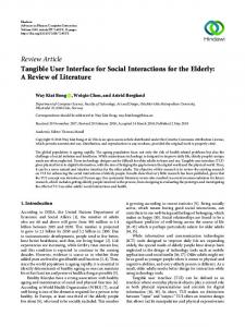
they remain as static productions of dynamic procedures. The absence of a live link between physical and digital design environments will most commonly result in the production of static forms where the digital and parametric framework is cutoff from the physical outcome. In other words, digitally fabricated parametric models provide limited value to the iterative design process, as they are incapable of physically demonstrating or updating their parametric relations, geometry, and information. Consequently, the research takes initiative to propose a method that extends the functionality of current tools and design methods to arrive at a novel approach for engaging parametric and BIM-based applications. The method will enable interaction to take place in the physical environment using design objects (elements), and provide real-time response and feedback to the user through an object's kinetic behavior. The prototypes are developed to demonstrate the method through integrating digital models and artifacts. The artifact is the system's physical component, which consists of a control system - with sensors and actuators - and physical objects representing architectural elements. In this research the artifact consists of a physical computing control system and a full scale section of a paneled surface with four panels. The artifact is linked to a digital model of the panels that is generated using Rhino and Grasshopper (Figure 1).
The research focuses on tangible UIs and interaction, and the prototypes presented in this paper are attempts to explore these notions. Physical computing systems provide the essential components to translate physical interaction into numeric data that could
622 | eCAADe 34 - BIM | Concepts - Volume 2
be used by the digital model. Physical computing also assists in the process of creating real-time data exchange between the digital and physical environments, which will allow users to interact with both models simultaneously. The benefits of the proposed method closely relate to the principles of tangible interaction presented by Hornecker and Buur (2006), which can be summarized in the following points: first, physical and material qualities of design objects provide essential feedback to the iterative design process; second, the existence of objects in actual conditions (physical context) allows for direct bodily interaction; and third, the link between both environment will assist users to develop a complete understanding of an architectural system by associating physical objects with their digital information.
Tangible Computing Tangibility, interaction, and response are key terms that define the current research, thus providing explanation for each will create the proper context for the work presented in this paper, and clearly state the different types of hybrid systems used in design today. Tangible User-Interfaces associate digital information with physical forms, thus proving users with the ability to manipulate digital information through their direct interaction with objects (Ishii 2008). Research in tangible UIs and interaction started in 1995 by Fitzmaurice, Ishii, and Buxton prior to the introduction of the term TUI by Ishii in 1997. Their work explored the link between "graspable" objects and graphical representations to establish a form of physical interaction. The graspable objects were specific in their method of interaction and data input, unlike GUI components, which are mostly generic in nature, i.e. could be used for various applications (Fitzmaurice et al. 1995). Tangible UIs link digital and physical environments together to create a hybrid medium for physical interaction, which is most commonly established by utilizing physical computing systems. Physical computing, in a broader sense is defined as the pro-
Figure 1 The hybrid system; left, the artifact consisting of a control system using physical computing components and architectural objects (panels). Right, a digital version of the paneled surface modeled using Rhino and Grasshopper.
cess of translating analog data into a virtual environment (O'Sullivan and Igoe 2004), and its system mainly consist of: microcontrollers, sensors, and actuators to create the interactive interface. Physical computing systems vary in their degree of interaction and response, and could be found in a wide range of applications in the arts and sciences. Hybrid interfaces vary in their degree of interaction and application. For that reason, it is best to describe their relationship to Milgram's spectrum of mixed reality (MR), which has two extremes, one being the real environment and the other being the virtual environment, and in between are augmented reality and augmented virtuality respectively (Milgram and Kishino 1994) as show in Figure 2. Figure 2 Milgram's spectrum of mixed reality (Milgram and Kishino 1994).
Augmented virtuality, describes the interaction with digital environments; and augmented reality, describes the interaction with objects situated in their physical environment (Hughes et al. 2005). The degree of user interaction varies from one extreme to the other along the spectrum. An example is virtual reality (VR), which is a technology based on information processing that generates and simulates graphical representations of actual - or hypothetical - objects and environments (Tegmark 2007). Generally, VR environments provide users with an elaborate style of interaction (involving a wider range of senses) compared to conventional GUI-based tools, yet objects in VR remain reserved in their native environment. Conversely, physical computing systems process analog information to communicate with a digital environment (O'Sullivan and Igoe 2004). In this research physical computing is used to create a TUI for interaction by linking physical objects with their digital information, a process referred to as embodied interaction. The process is defined by an alternative MR than the previously stated where the continuum is in a closed loop rather than defined by two extremes
(Salim et al. 2011; Dourish 2001). Comparing physical computing and other mixed reality models for design helps to establish the context for this research and highlight the key differences between the different types of hybrid systems.
Related Work and Significance Previous research has shown the possibility of establishing a form of communication between the digital and physical environments (Kensek 2014), which utilizes environmental sensors to detect humidity, co2, and daylight levels to inform BIM geometry and physical models. Another example uses a different approach in utilizing physical computing through the use of Wii remote controllers to interact with parametric models (Salem et al. 2011). Both examples provide insight into the use of different types of analog inputs and physical interaction to engage digital parametric and BIM-based models. Many more examples in architecture and design exist today that demonstrate variations of physical computing setups. In addition, software tools, including Firefly (a plugin for Grasshopper), have also streamlined the communication process between the two mediums, which in return has provided users with the opportunity to easily establish communication between digital and physical environments. In this paper similar communication methods and tools are adopted to manage data exchange between analog sensors and digital models. Tools utilized for this research are updated versions of the ones used in previous works, such as Dynamo, Firefly, etc. However, the significance of the work is found in the manner in which physical computing systems are utilized. The proposed method and prototypes mainly investigate user interaction and system response to inform parametric models. The interface utilizes different analog sensors that promote different styles of user interaction rather than sensing the physical environment. The prototype focuses on providing tangible objects that represent architectural elements rather than remote controllers, which users could easily identify and are familiar with, thus
BIM | Concepts - Volume 2 - eCAADe 34 | 623
making the physical interaction with digital designs more intuitive for them. Last the prototype utilizes digital fabrication methods and machinery, and customized parts to enable complex physical responses. The research focuses on establishing a sophisticated medium for design interaction and response that encourages the users' personal involvement as designers in a digitally based process.
Tools and Techniques In the experiments different variations were done to the physical computing setup. Each attempt investigates different types of sensors, actuators, and methods to link both environments. For clarification purposes, hardware and software tools that are utilized for this research are organized in three groups: Modeling tools: are used for geometric generation and transformation, and design data manipulation. The tools used for the experiments include: Revit (a BIM authoring tool) and Dynamo (a visual programming environment and add-on for Revit); and Rhino (a 3D modeler) and Grasshopper (a visual programming environment and a plug-in for Rhino). Data management tools: are used for data (analog and digital) exchange between the two environments. Tools include: Processing (an open source programming language and Integrated Development Environment, i.e. IDE), PLX-DAQ (plugin for MS Excel and Arduino, developed by Parallax Inc., [1]), Firefly (developed by Andrew Payne, [2]), and Microsoft Excel. Physical computing components: such as sensors, actuators, and microcontrollers are used to create the prototypes' control system and their kinetic capabilities. The analog sensors chosen for the experiments are operated through user input, and each provides a different form of interaction. The sensors include: rotary potentiometers and ultrasonic distance finders (referred to as proximity sensors). The actuators enable objects to demonstrate physical responses, which provides users with physical feedback regarding the object's mechanics and kinetic
624 | eCAADe 34 - BIM | Concepts - Volume 2
performance. The actuators used for this experiment are mainly servo motors (standard and high torque). The microcontroller type used for the experiments is an Arduino (MEGA 2560, [3]) that includes a single CPU chip with limited RAM and ROM to manage the data exchange process between the different components of the system. Arduino is also a reconfigurable devices making it useful for a wide range of real-time applications, thus making it a proper choice for this research.
Framework and Prototyping The hybrid system consists of two parts that are linked together using a physical computing system. The system is operated by user analog input, once the system receives data, the models in both environments respond accordingly in a synchronized manner providing visual and physical feedback (Figure 3). Figure 3 prototypes’ workflow.
Each experiment investigates a different method of physical interaction and TUI. The variations made to the physical computing system (using different sensors and actuators) and linkage methods were for the purpose of improving the interactive experience of the UI. The experiments are listed below according to their type of linkage: • Physical to digital: Dynamo, Arduino, proximity sensor, potentiometer, MS Excel, and PLX-DAQ. • Digital to physical: Dynamo, Arduino, actuators, MS Excel, and Processing. • Hybrid system: full scale physical objects, Grasshopper, Firefly, Arduino, proximity sensors, and actuators.
Prototype 1: Physical to Digital The first experiment tested a simple form of physical interaction with a unidirectional link that allows sensor data to flow from the control system to the digital model. The link was established using MS Excel and the plugin PLX-DAQ (Figure 4). Figure 4 workflow for Prototype 1 (circuit documented using Fritzing, [4]) Figure 5 Left, the control system using an Arduino circuit and two sensors (proximity and potentiometer); right, the two masses modeled in Dynamo.
Figure 6 Serial port communication using the Arduino IDE, MS excel, and the PLX-DAQ plugin.
The prototype includes two types of analog sensors: a rotary potentiometer and a proximity sensor (ultrasonic distance finder). In this example the artifact includes no physical objects, and the prototype is operated by directly interacting with the sensors. The digital model generated in Dynamo consists of simple geometric masses and two transforming parameters. Each parameter is linked to one of the masses, and to one of the sensors on the control system (Figure 5). As a result, if a sensor in the control system is operated the digital mass linked to it will display one type of transformation. Each mass in Dynamo is assigned to display one type of the following transformations (motions): rotation or horizontal movement. The masses' parametric behavior is constructed to reflect the manner in which the user will interact with the control system; e.g. if the potentiometer is operated by rotating its handle, the mass linked to it will rotate. Data communication between the control system and Dynamo was established through PLX-DAQ
and the computer's serial port. The setup using PLXDAQ allowed for a live data stream from the sensors to the digital environment. Sensor data is sent by Arduino in a CSV format (Comma Separated Values) to PLX-DAQ, and afterwards was arranged in an MS Excel spreadsheet. MS Excel arranges the values of each sensor in a separate column, and the latest value from each in a new raw (Figure 6). Data arrangement and formatting was initially set in the Arduino code. In Figure 6, sensor values in the MS Excel table were rounded up. The column on the left, states "V" for value to notify the user of the type of data being received; the middle column includes the distance measurements in inches provided by the proximity sensor; and the column on the right includes rotation angles obtained from the potentiometer. The MS Excel file with sensor values is saved on the computer's local drive. Dynamo afterwards locates the file, extracts the values, and sends them to their assigned parameters in the model. The data exchange process in this setup is automated and in realtime. This was achieved by using a MACRO for MS Excel, which automates the save function, and as a result, the CSV file will always include the updated sensor values for Dynamo to use. Interaction with the sensors matches the type of parameters created in Dynamo; e.g. potentiometer is a rotary sensor, which provides angles of rotation; and the proximity sensor measures distance, which provides movement values. Therefore, each parameter in Dynamo is setup to receive its values from its corresponding sensor.
BIM | Concepts - Volume 2 - eCAADe 34 | 625
The first mass created is located at the origin of the world coordinate system, and displays rotation. Its angles of rotation values are provide by the potentiometer. Once the mass receives sensor data, it will respond accordingly by rotating in place (around the origin and the z-axis). The second mass created is linked to the proximity sensor and displays horizontal movement, which corresponds to the manner in which the user will interact with the sensor. Horizontal movement demonstrates a simple parametric relationship that could be constructed and operated physically. To further explain, the proximity sensor detects nearby objects, and then it measure its distance from them. The sensors and the orange cardboard (shown in Figure 5) demonstrate a similar relationship to the masses in Dynamo; e.g. if the cardboard is moved closer to or away from the sensor the masses will demonstrate similar behavior. The sensor measures the distance to the cardboard and sends the data to Dynamo, and then used as parameter input values. The translation parameter moves the second mass horizontally closer or farther away from the first mass along the X-axis (Figure 7). The experiment tested a simple form of TUI where the users interact with the digital model through operating the sensors. Sensors' setup relates to geometry transformation in Dynamo (rotation and movement), thus making the interaction process straightforward for the user. The link in this example has made the process of monitoring the data flow and navigating the UI inconvenient, as a result of running the different program applications together for data exchange between the control system and the digital model.
Prototype 2: Digital to Physical In this experiment the data exchange process is reversed making the flow of data from Dynamo to the
626 | eCAADe 34 - BIM | Concepts - Volume 2
artifact to test the prototype's kinetic responses. The artifact in this experiment consists of two servo motors with a cardboard piece attached to each of their rotating arms. The cardboards help in creating a simple physical representation of the digital model that would provide visual and physical feedback regarding the systems performance. Both environments are linked together through utilizing the tools implemented in Prototype 1, however the plugin PLX-DAQ in this example is replaced with Processing (Figure 8). Processing improved the link between the artifact and the digital model by reducing the number of running program applications down to two, i.e. Processing and Dynamo. The UI in this setup made the process of monitoring dataflow and navigating the UI more convenient in comparison to the previous experiment.
Figure 7 Masses receiving analog data from the sensors. Mass 1 (left) rotates around the Z-axis and origin, and is transformed by the potentiometer; and Mass 2 (right) moves horizontally along the X-axis, and its translation values are obtained from the proximity sensor.
Figure 8 Workflow for Prototype 2.
The digital model from Prototype 1 is used for this experiment with some modifications done to the masses; both masses in this example demonstrate rotational motion. The reason is to correspond the digital models' type of transformation with the servos' rotational movement. The servos and digital masses are operated through a single parameter input, which provides angles of rotation values. In addition, the Dynamo model is imported into Revit to expand the functionality of the system by including a BIM authoring tool. This approach helps to establish a framework to associates digital design information with physical objects for future work. The Revit model and the artifact showed synchronized responses when parameter values were updated using a number slider (Figure 9). The prototype helped demonstrate the physical limitations when attempting to create a kinetic and responsive object. This in-
cludes constructing digital and physical models with matching dynamic capabilities, e.g. digital objects must use similar types of motion that correspond to the actuators. Figure 9 Left, the artifact; and right, the Revit masses imported from Dynamo. The example shows both masses rotating once the values of the rotation parameter in Dynamo are updated.
Creating a setup that allows digital and physical objects to demonstrate matching motions will help users to relate responses from both environments to each other, thus making the interaction meaningful and controllable for them. The model in Revit, showed a synchronized response using the linkage method described. Further attempts to utilize BIM databases are not explored in this example. However, the aim was to establish a form of communication between the physical object and the BIM authoring tool for further investigations.
Figure 10 Artifact, showing the physical architectural objects (panels).
lights, and two microcontrollers. The physical object represents a full scale section of an architectural element, i.e. a paneled surface with four Panels (Figure 10). The control system and the physical objects in this example create an interactive and responsive artifact capable of demonstrating complex kinetic behavior in physical space. The artifact is linked to a digital model through the plugin Firefly to enable real-time and bidirectional data exchange. The digital model of the paneled surface is created using Rhino and Grasshopper (Figure 11). The objective of using an alternative digital modeling tool is to test the artifact's interactive capabilities with a different modeling environment. The main consideration when selecting a modeling tool for the research was its parametric capabilities and/or association with BIM information. Each physical panel on the surface is capable of rotating in two axis - referred to as Pan and Tilt motions - to demonstrate rotations at different angles. The panels' pan and tilt motions were achieved by attaching each panel to two servos using a U and C shaped aluminum brackets (provided by Lynxmotion, [5]). The assembly will allow each panel to rotate in two different axis (Figure 12). The rotation angles for each type of motion is obtained from a single proximity sensor in the control system. The microcontroller receives the sensor values and remaps them to match the servos' range of motion, afterwards the new angle values are sent to both the panels and the digital model.
Figure 11 Workflow for Prototype 3.
Prototype 3: Hybrid System Prototype 3 integrates the methods previously stated to establish an interactive and responsive hybrid system. The control system includes: eight high torque servo motors, two proximity sensors, sixteen LED
BIM | Concepts - Volume 2 - eCAADe 34 | 627
The aim of the prototype is to provide users with full scale architectural objects with actual building materials. This will enable the prototype to convey physical qualities of the design in addition to digital information. Therefore, to construct and fabricate the different architectural elements, having actual materials, digital fabrication machinery and methods were used. The two type fabrication methods that were used for this experiment are: additive manufacturing, using 3D printing (stereolithography); and subtractive manufacturing, using laser cutting. The material used for the panels is Plexiglas with various thickness to manage the panels' weight. In this context, the use of digital fabrication methods logically tied the design and manufacturing processes together to create a complete workflow for the project (Figure 13). Physical limitations associated with design objects and the mechanics of their dynamic behavior commonly pose a challenge to the process of developing tangible, interactive, and responsive UIs. The specifications of the electromechanical components, and the physical characteristics of the architectural objects - including material and geometry - determine many aspects of the system's performance. The cost value of the prototype at this stage including building materials, customized parts, and electrome-
628 | eCAADe 34 - BIM | Concepts - Volume 2
chanical and electrical components may affect its implementation in certain design settings, such as in a design studio. However, implementing interactive systems in an architectural project may provide the opportunity for further savings during a project's design and construction phases. AEC professionals have used similar methods with full scale physical mockups for simulations (e.g. wind and solar studies). With this present approach, the system provides the benefit of integrating both the physical and digital models together for establishing information and geometry relations, and the possibility of iterating the design, because of the objects' kinetic capabilities. In addition, sophisticated setups, such as the prototype presented, are not energy demanding. The artifact in this experiment is running on 10 volts, separated into two circuits with 5v for each. However, the challenge is to determine the adequate levels of electricity and type of circuit required to properly run and operate the physical computing components.
Figure 12 Testing the response of the artifact (left) and digital model (right).
Figure 13 Left, the proximity sensors’ 3D printed stand; middle, the U and C aluminum brackets (by Lynxmotion) ; right, the Plexiglas frame and panel support.
Figure 14 The artifact being presented at an exhibition (without the digital model) for visitors to interact with.
In summary, Prototype 3 tested a bidirectional and live link to interact with digital and physical models simultaneously with a set of sensors that were straightforward and intuitive for the users to operate. The proximity sensors allows users to freely operate the hybrid system by simply maneuvering their hands in front of them, which is less restrictive than
other types of sensors (Figure 14). LEDs are used as an additional feature to the artifact, they provide users with basic types of information, e.g. the system is active or a certain panel, or object, is being operated. Therefore, the capabilities of the artifact using a sophisticated physical computing setup and actual building materials allowed for a complete design experience that offers feedback in physical and digital form.
Figure 15 Artifact (left) and BIM model linked to evaluate a kinetic panel’s design for shading.
Discussion
the physical context, where the architect thinks of relationships directly between the design objects, and the hybrid system translates the architect's physical relationships into the digital environment. Therefore, utilizing physical computing systems to detect physical object relationships and reconstructs them in the digital environment provides a benefit to the parametric design process and practice that extends the functionality of modeling tools. Future work for this research will investigate this feature for the development of the hybrid system.
The interaction with physical world objects makes us experience their true qualities through our senses, thus providing us with more information than what could be perceived on a screen. Consequently, hybrid systems aim to make these tangible qualities available for architects to properly engage in digital design processes. Physical computing systems helps users to physically interact with parametric models in their native environment. Prototypes 1 and 2, used a simple setup for the artifact that allows users to establish a relationship between digital and physical objects' responses, and sensor analog input. This connection was further explored in the development of Prototype 3. The process of creating Prototype 3 is closely related to a conventional design process with a feedback loop where its objects' kinetic behavior, geometry, and relationships were constantly informing each other during the progress of the work. Nevertheless, the control system in the prototypes presented only provided analog data to the system where the parametric relationships are predefined and constructed by the user. As commonly known, the prevalent feature of a parametric models is in the explicit creation and use of relationships. Currently, the process of constructing parametric relationships to manage geometric and non-geometric information pose a challenge for architects, especially when working on complex architectural systems. Tangible UIs and interaction could be fostered to establish these relationships in the digital model. To further explain, the interaction may take place in
An example of work in progress is included in this section that demonstrates the use of physical computing systems in the context of kinetic shading design. The work focuses on the aspect of extending the capabilities of design tools by associating design objects' physical properties, BIM's geometric and nongeometric information, and simulation tools such as DIVA (Figure 15) to provide AEC professionals with a hybrid system that allows them to properly explore and evaluate an architectural system. Non-geometric information refers to digital design data that is associated with an architectural element in a BIM model; such as: an element's parameters, material properties, etc. The artifact includes a single panel with a reflective surface that is capable of rotating in three axis; two axis are used for sun tracking, and one axis is used to provide users with an additional level of control. Users operate and control the hybrid system through digital parameters and smart devices (e.g. smart phones, tablets, etc.) that are linked to both the artifact and the digital model. The Revit model in this experiment is adapted from the work done by Jeremy Roh (School of Architecture - UNC Charlotte, [6]), which provides a good example for testing the
BIM | Concepts - Volume 2 - eCAADe 34 | 629
system. However, further adjustments were made to the Revit model and to the Dynamo graph to ensure their compatibility with the artifact.
Conclusion The research focuses on developing a Tangible, interactive, and responsive UI for parametric and BIM applications through utilizing physical computing systems. The research aims to investigate the possibilities of extending the functionality of design tools by linking digital and physical design models. The experiments focused on developing methods that would allow AEC and non-design oriented users to expressively engage parametric and BIM-based designs. The kinetic capabilities of the hybrid system provides users with means to physically experience the qualities of a design while providing them with essential feedback in physical and digital form, which is related to the design's geometry, parametric relationships, and information. In summary, the value of the system to users which mixed reality applications may not offer are: first, having the ability to interact with digital designs through physical objects, which directly relates to the manner in which we naturally engage objects in our physical environment; second, the physical existence of objects in an actual context provides users with the ability to experience firsthand the qualities of space, geometry, and materials; and third, the system's kinetic ability provides feedback in a physical form that would assist in further understanding the relationships governing an architectural system, and as a result, it would better inform our design process.
REFERENCES Dourish, P 2001, Where the action is: the foundations of embodied interaction, MIT Press, Cambridge Fitzmaurice, GW, Ishii, H and Buxton, B 1995 'Bricks: laying the foundations for graspable user interfaces', Proceedings of the ACM CHI 1995, Denver, Colorado, pp. 442-449 Globa, A, Donn, M and Twose, S 2010, 'Digital to physical: comparative evaluation of three main CNC fabricating technologies adapted for physical modeling in architecture', Journal of Architectural Computing,
630 | eCAADe 34 - BIM | Concepts - Volume 2
10(10), pp. 461-480 Hornecker, E and Buur, J 2006 'Getting a grip on tangible interaction: a freamework on physical space and social interaction', Proceedings of ACM CHI 2006, Montreal , pp. 437-446 Hughes, CE, Stapleton, CB, Hughes, DE and Smith, E 2005, 'Mixed reality in education, entertainment and training: an interdisciplinary approach', IEEE Computer Graphics and Applications, 26(6), pp. 24-30 Ishii, H 2008 'Tangible bits: beyond pixels', Proceedings of the Second International Conference on TEI 2008, Bonn, Germany , pp. 15-25 Ishii, H and Ullmer, B 1997 'Tangible Bits: Towards Seamless Interfaces between People, Bits and Atoms', Proceedings of the ACM CHI 1997, Atlanta, Georgia, pp. 234-241 Kensek, K 2014, 'Integration of environmental sensors with BIM: case studies using Arduino, Dynamo, and the Revit API', Informes de la Construccion, 66(536), p. e044 Milgram, P and Kishino, F 1994, 'Taxonomy of mixed reality visual displays', IEICE Transactions on Information Systems, E77-D(12), pp. 1321-1329 O'Sullivan, D and Igoe, T 2004, Physical computing: sensing and controlling the physical world with computers, Thomson Salim, FD, Mulder, HM and Burry, JR 2011, 'Form fostering: a novel approach for interacting with parametric models in the embodied vitality', Journal of Information Technology in Construction, 16, p. 133–148 Tegmark, M 2007, 'The mathematical universe', in Chiao, RY, Cohen, ML, Leggett, AJ, Phillips, WD and Harper Jr., CL (eds) 2007, In visions of discovery: shedding new light on physics and cosmology, Cambridge university press [1] http://www.parallax.com [2] http://www.fireflyexperiments.com [3] http://www.Arduino.cc [4] http://www.fritzing.org [5] http://www.lynxmotion.com [6] http://www.jrohdesign.com