Proposal of the IPv6 QoS System Implementation in Virtual Infrastructure A
Halina Tarasiuk*, Slawomir Hanczewskit, Adam Kaliszan t, Robert Szuman+, Lukasz Ogrodowczyk+, I wo Olszewski+, Michal Giertych+, Piotr Wisniewski*
*Institute of Telecommunications, Warsaw University of Technology, Warsaw, Poland Email:
[email protected] tChair of Communication and Computer Networks, Poznan University of Technology, Poznan, Poland Email:
[email protected] +Poznan Supercomputing and Networking Center, Poznan, Poland Email:
[email protected]
Abstract-The concept of network virtualization offers the promising possibility for parallel deployment of network solutions that can be based on different protocol stacks. The way of implementation of network virtualization plays essential role in deployment of the mentioned concept. This paper proposes a novel solution for implementation of the IPv6 QoS System in the virtualized environment. This system exploits moreover modern network solutions like: IPv6 protocol, data and control plane separation, and it follows NGN and DiffServ architectures.
I.
INTRODUCT ION
Nowadays, Future Internet (in Europe) also called as New Generation Networks (in Japan) or Internet 3.0 (in US) is one of the most important research challenges. Many national and international projects as well as standardization bodies (as ITU-T, IETF) focus on topics in this area. Virtualization is one of the most important new technologies considered for Future Internet [1]. In our paper we pay the attention on network virtualization. More precisely, we provide a proposal of the IPv6 QoS (Quality of Service) System implementation in physical network infrastructure enabling virtualization of network nodes and links. The system is proposed in the scope of the Future Internet Engineering (lIP) project [2]. The aim of the project is to develop 3 Parallel Internets (one IP-based and two post-IP) on the top of the network infrastructure enabling virtualization. The proposed lIP architecture consists of 4 main levels [2]: level 1 - Physical infrastructure, level 2 Virtualization, level 3 - Parallel Internets, level 4 - Virtual networks. Virtual networks on level 4 can be created for specific Parallel Internet based on logical separation of routing tables. Following this architecture we distinguish two levels of virtualization in the system, at level 2 and at level 4. In the paper we will show on the one hand a description of the implementation of the IPv6 QoS System features as data and control planes on dedicated virtual node, on the other hand also the implementation of level 4 routing dedicated for This work has been partiaUy supported by the Polish Ministry of Science and Higher Education under the European Regional Development Fund, Grant No. POIG.Ol.Ol.02-00-045/09-00 Future Internet Engineering.
978-1-4673-1391-9/12/$31.00 2012 IEEE
IPv6 QoS virtual networks. The implementation example of the IPv6 QoS network node we will show for EZappliance [9], programmable network processor. Taking into account current state of the art in the area of IPv6 QoS solutions, our approach is based on NGN and DiffServ architectures [3], [4]. However, comparing with proposals considered in the literature e.g. [5], we show a proto type implementation in environment of physical infrastructure enabling virtualization. For this purpose, we developed QoS mechanisms at packet and call levels, which allow to support strict QoS guarantees [6]. Moreover, we provide a solution based on "IPv6 in IPv6 tunnels" for deploying the level 4 routing of virtual networks. In that way, we exploit features of IPv6 protocol. We name the presented approach as the IPv6 QoS Parallel Internet. It is worth to mention that the proposed solution could be also implemented as a separate IPv6 QoS System. Comparing our approach with other proposals in the area of virtualization, for example with results of 4WARD project [7], we provide the original solution. In 4WARD it was proposed a concept of nodes virtualization, however the solution was considered only for nodes operating on IPv4 protocol and dedicated for best effort network. In our approach as we mentioned before we focus on IPv6-based proposal and for this proposal we deploy appropriate QoS mechanisms for assuring strict QoS guaratees [6]. In our proposal we also exploit a concept of a separation between data and control planes in a single network node. The most popular open platform, which follows this idea is Openflow [8]. It separates data and control planes by providing a dedicated standardized interface. However, based on our best knowledge this approach does not support any QoS mechanisms. Therefore, we provide our own solution to build an IPv6 QoS nodes by separating data and control planes. The proposed control plane solution for the IPv6 QoS Parallel Internet is different from the solutions used so far. The most common one is a full virtualization of both, data and control plane. Such a solution can only be used on
A lications
m
IPv6Qos
ANI
r------------------------------
SCF
Service stratum
------------------------------
1
IPv6QoS Management
J)
Control Plane
IPv6Qos Data Plane
M
055 Control Plane
055 Management
055 Data Plane
J
CAN CAN Management
J J
Control Plane
CAN Data Plane
System liP: physical node enabling virtualization g
J
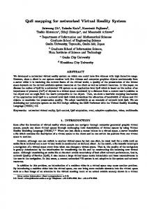
Fig. 2. Main functional blocks of the prototype device enabling virtualization (DSS - Data Stream Switching, CAN - Content Aware Networks
I
UN!
UN] DiffSelV Architecture
Fig. 1.
Transport stratum
Ethernet Switch
[
IPv6 QoS architecture
devices ensuring a full virtualization. It requires the significant reserves of discs, memory and CPU time. A separation of data plane and control plane caused that control plane became independent from the data plane hardware platform. The way of virtualization of routing functions makes a considerable difference, if comparing the existing solutions. Herein, the routing functions are implemented independently within one process, owing to the co-routines. This simplifies a manage ment and decreases the hardware requirements. The paper is organized as follows. Chapter 2 describes more details about the IPv6 QoS System. Chapter 3 provides a concept of routing and virtual networks for this system. Chapter 4 discusses implementation aspects of the IPv6 QoS node. Chapter 5 provides exemplary results of control plane performances. Finaly, Chapter 6 concludes the paper. II. IPv6 QoS
SYSTEM
In this chapter we introduce more details about the IPv6 QoS System. In particular, we describe the IPv6 QoS archi tecture and the IPv6 QoS node as one of the virtual nodes of the lIP System. A. IPv6 QoS Architecture
Fig. 1 shows the proposed IPv6 QoS architecture. As we mentioned before, it follows ITU-T and IETF recommen dations [3], [4]. The architecture consists of transport and service stratums. These stratums connect with management functional blocks and applications/service layers. Moreover, since the IPv6 QoS Parallel Internet has been defined at level 3 of the lIP architecture, it provides also interfaces to level 2 and level 4 of the lIP architecture. In our approach we specify the resource and admission control functions of the NON architecture (PD-FE - Policy Decision Functional Entity, TRC-FE - Traffic Control Functional Entity) for single IP domain and access networks (see Fig. 1). The PE-FE (Policy Enforcement Functional Entity) elements specific for underlying network technologies have been developed for setting the policy decision parameters in transport network nodes.
PE-FE
Control Plane
( Fig. 3.
[
IPv6 QoS Adapter Control Plane
Adapter (CPA)
J
Configuration & management
Data Plane
EZ/NetFPGA/XEN
)
Prototype model of the IPv6 QoS network node
B. IPv6 QoS Node
For the purpose of the lIP System, a concept of an ideal device enabling virtualization have been proposed [2]. Fig. 2 shows the main functional blocks of the prototype device enabling virtualization. It presents 3 virtual nodes on the top of the lIP System part responsible of functions enabling virtu alization. According to the prototype specification virtual node of each Parallel Internet is composed of data plane and control plane modules, as well as of management functional blocks. Each of these modules follows unique protocol stack. The virtual node of the IPv6 QoS Parallel Internet follows simply TCPIIP protocol stack. Two other virtual nodes are dedicated to Data Stream Switching (DSS) and Content Aware Networks (CAN) Parallel Internets, respectivelly. Fig. 3 presents the prototype model of the IPv6 QoS network node. Elements of the proposed model are the following: data plane, IPv6 QoS adapter, control plane adapter, configuration and management, control plane. PE-FE element is a part of the signaling system, which allows to communicate with the network node. As we can see, the control plane element could be implemented in a separate device. In fact, we could implement the control plane of the IP network in one centralized device. It simplifies the management process. The presented model is similar for 3 considered technology platforms, EZappliance, NetFPOA [10], and XEN [11]. However, in this paper we will describe the implementation aspects on EZappliance only. More details about the control and data planes implementation we provide in the next chapters of the paper. III.
ROUTING AND V IRTUA L NETW ORKS
A. Routing
To implement the routing functions in the IPv6 QoS net work, the OSPFv3 protocol was chosen. Under the agreed assumptions the protocol needs to implement the routing
functions for the IPv6 QoS network and for all other virtual networks, being its part. The protocol OSPFv3 was designed in such a way to stay independent of the set of protocols that are operating in network layer of OSI model. The previous version of OSPF protocol (designed for IPv4) didn't include this feature, hence elaboration of new version of protocol for IPv6 was required. By adopting these assumptions the protocol can be potentially used for calculating of routing paths in post IP networks. The OSPF protocol is characterized by high operating stability, which is a big advantage by network dimensioning. This protocol is also scalable, owing to the possibility of network partitioning into areas. Such advantage may be used in the course of further research carried out within the lIP project. Specification of OSPFv3 protocol is free of charge [12], which enables its implementation in open source projects of software routers like for example Quagga [13] or Xorp [14]. It should be underlined that choosing a routing protocol, which is running stably, ensures a proper functioning of the network built. Hence, the implementation available in Quagga project has been chosen as a base implementation of the routing protocol. The Fig. 4 presents a structure of the IPv6 QoS network in a view of the routing functions implementation. The considered network on level 3 is built of core and edge nodes. The aim of OSPFv3 protocol on this level is to calculate optimal and stable route paths between all network nodes. By defining the paths between edge routers it will be feasible to send the packets between the nodes, that belong to virtual networks and to send signal messages. Path information will also be useful in dimensioning of the network resources, which are available for specific services offered in virtual networks. The virtual networks are implemented in level 4 of the lIP System. These networks are not aware of the level 3 structure. The only common element of the virtual networks and the IPv6 QoS Parallel Internet are the edge routers, which are connected to virtual networks. Moreover, from the viewpoint of the virtual network, nodes are connected to common link (star topology). As each of the virtual network is attached to other client networks, they need to have a separate routing process running. In accordance with the given assumption, the core nodes are supposed to mediate in the transmission of packets (forward them) between edge nodes (the scope of functionality of these nodes is similar to the functionality of such nodes in the conventional networks). It is different in case of edge nodes that implement the routing functions on level 3 and simultaneously act as the points, that join the virtual networks (level 4) with the network of level 3. To ensure the communication between the given parts of virtual networks it is necessary to launch the right number of dedicated (and isolated) routing processes (protocol OSPFv3) in edge routers. The selection of OSPFv3 protocol on level 3 and 4 ensures proper work of the IPv6 QoS network. The routing specification for the IPv6 QoS network assumes that the routing functions are implemented separately within a single OSPFv3 protocol process. With such a solution the use of resources necessary to build a node has been reduced and
,,
---
: ..... --
I
:
:
L4 VN2::---
''
I
I
1-----
1
: �
:
I 1 1 .L� ______ • ___ _________________ I I I � I
+
L4 VN1 ___
, ! +
:
_
_
: :
I
L3
, ' i .
:
:
� : � !E� i' �----�: \ :
:
______________
I
! �!
....
/ : �� C R
�
�--E-R--
\
1.+
-...
I
: i
______ _
:
I
i �i
�--ER-: �..t-.. :
Fig. 4. Routing in the IPv6 QoS network (CR - core router, ER - edge router, L3 - level 3, L4 - level 4, VN - Virtual Network)
the process of managing the nodes has been simplified. B. Virtual Networks
Dedicated virtual networks (VN) are created on level 4 of the lIP architecture on the basis of resources of the IPv6 QoS Parallel Internet. Every single VN is created in long term scale i.e. days, months by Virtual Network Operator (VNO) based on Service Provider (SP) request for group of applications e.g. e-health. VN may connect two or more locations over one core network domain. VN creation depends on the requirements of a service/application, which are gathered from the SP by the VNO who is responsible for the creation, modification or removal of the VN via the management functions of the IPv6 QoS System. Based on these requirements the proper set of nodes and links is provided by Parallel Internet Operator (PIO) to SP. VN can be built with different Virtual Private Network (VPN) services [15]. VPN is a network composed of a mesh of tunnels between end points established mostly across public networks. This kind of network offers traffic isolation and se curity depending on the chosen technique. We have considered three common VPN services created on provider edge nodes: VPWS (Virtual Private Wire Service), VPLS (Virtual Private LAN Service) and Layer 3 (ISO/OSI) VPN (L3 VPN). Finally, we have chosen L3 VPN as a technique for the creation of VN in the IPv6 QoS Parallel Internet, because clients do not have to realize their own routing protocols which are delivered by VN Provider. Such L3 VPN acts like an IP subnet which connects customer IP networks located in different sites. IP addresses do not have to be unique between different L3 VPNs because a separate virtual routing table (VRF) is created for each L3 VPN on a provider edge router. An IPv6 VPN can be made in many different ways e.g. as BGPIMPLS VPNs [16] or through different tunnels tech niques operating on top of IP protocol. The first approach actually needs a dual-stack IPv4/IPv6 due to lack of full IPv6 implementation for LSP creation. For the reason that we do not consider to use IPv4 protocol in our solution we recommended to use tunnels to create VNs. Tunnels can be established with the IPsec, IPv6 in IPv6 or GRE (Generic Routing Encapsulation) protocols for packet tunneling. The data encapsulated by all of them is presented in the core
112
�4
o Ver.
Traffic Class
Flow Label (VN Number)
1 32
Edge Router Source Edge Router Ver.
Traffic Class
Flow label
Payload length
148
Next Header
156
Address
Next Header
Hop Limit
Client Source Address Client
ZEBRA client
ISi;c;mA)
I
J
J
Port number: 2001 OSPF L3/L4
2000 ZEBRA protocol
Fig. 5.
I
IPv6 in IPv6 tunnel header example
packets ETHERNET
network as typical IPv6 packets. In our solution we have chosen IPv6 in IPv6 encapsulation mechanism [17] because there is no need for packet encryption (IPsec) and it is slightly simpler for handling than processing GRE packets. This approach does not require any additional protocols or packet types as it utilizes standards features of IPv6 protocol and it is based on the Generic Packet TunnellIng in IPv6 Specification [18]. Each packet is encapsulated into another that both source and destination IPv6 addresses are tunnel end-points. Additionally, providing QoS in the VN is simplified because the entire Traffic Class field is directly copied from the original IPv6 packet (payload) to the outer packet header and there is no further need for analyzIng packets' payload so the packet processing time by network core nodes is reduced. Outer packet header "Flow Label" field contains a numeric identifier of VN to distinguish traffic and QoS between different VNs. This value is assigned by the system management during the VN creation process. In our solution every client's IP packet will be preceded by a new IPv6 header (as it is depicted on Fig. 5). Source Address field in the new header will contain an IP address of ingress edge router which is tunnel entry point node for each packet and Destination Address field will contain IP address of egress edge router - tunnel exit point node. The Traffic Class field value from original (client) packet header will be copied to the new header without any modification. This operation will allow core routers to properly treat such packet without looking into inner IP header. The Flow Label field of the outside header will contain virtual network number. All 20 bits of this field are reserved for this number. The Hop Limit field will be initially set to value of 32 by ingress edge router and decreased by 1 on every core network router which will transmit this packet. The meaning of Version, Payload Length and Next Header fields will be also consistent with IPv6 specification [17]. The Hop Limit field of inner IP packet header will be decremented only by ingress and egress edge routers so the core network infrastructure will be hidden from client hosts. Other fields in original header will not be changed.
IV.
IMP LEMENTAT ION
ASPECTS OF IPv6 QoS EDGE
NODE
A. Control Plane
The control plane (CP) functions are implemented via program router. Originally, it was considered to use one of the program routers: XORP [14] or Quagga [13]. However, due to the router stability and the implementation of OSPFv3
Monitor
ZEBRA server
J
II
EZ, NetFPGA, XEN
Fig. 6.
I �
L: � IP 1P2/641J
C
II
Control PI ane
ISPci