A typical ICS system consists of: a control center, one or more field devices, a .... OKL4 system call that blocks until it receives an IPC message, delivered by the ...
A Prototype Security Hardened Field Device for Industrial Control Systems
2
Jeffrey Lloyd Hieb1, James H. Graham2, Brad Luyster2 Department of Electrical and Computer Engineering, 1Department of Engineering Fundamentals J.B. Speed School of Engineering, University of Louisville Louisville Kentucky, 40292 [jeff.hieb][jhgram01][baluys01]@louisville.edu
Abstract Field devices are the part of an industrial control network that connects the control network to actual hardware through analog and digital IO. The lack of network isolation and the use of commercial hardware and software has made field devices vulnerable to cyber based attacks. This paper described work on developing a prototype security hardened field device using a microkernel to isolate software involved in interfacing to the control network from security related software (and storage) and IO control software. Three independent CELLS are created using the OKL4 microkernel running on the Verdex board from Gumstix. Inter-process communication (IPC) between CELLS is controlled by the kernel and the prototype demonstrates the feasibility of using this to prevent exploited vulnerabilities in network facing software from by-passing security measures and operating IO directly. IPC exacts a performance cost that could negatively impact the prototype. Results of benchmark timing show the response time of reading or writing analog and digital IO via the intended IPC path to be very low, ranging from about 350 to 550 microseconds. 1
Introduction
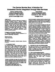
Supervisory control and data acquisition (SCADA) and distributed control systems (DCS) are networks of computer based systems that provide remote telemetry of physical systems and processes. Collectively they are referred to as Industrial Control Systems (ICS). ICSs play a central role in the daily operation of a vast array of services and infrastructure on which we have all come to rely; these include: electric power, fresh drinking water, waste water treatment, gas distribution, industrial manufacturing, and many others. A typical ICS network architecture is shown in figure 1.1. A typical ICS system consists of: a control center, one or more field devices, a communications infrastructure, and field equipment. At the control center a Master or Master Terminal Unit (MTU) processes information received from field sites and sends control directives back out to field sites. Human operators or control algorithms initiate control signals from the control center. Field operations are carried out by field devices which are connected to field equipment, sensors and actuators, through analog and digital input and output (IO) hardware. Common types of field devices are remote telemetry units (RTU), intelligent electronic devices (IED) and programmable logic controllers (PLC). Field devices and the Master are connected by a communications network. The communications network could be leased lines, PSTNs, cellular networks, IP based landlines, radio, microwave, satellite, or industrial Ethernet. In general the communication
protocols used by field devices and Masters are referred to as SCADA protocols.
Figure 1.1. Typical ICS network architectures [1]. When these systems were initially developed little attention was paid to cyber security since these systems were physically isolated and used proprietary hardware, software, and communication protocols [2-6]. For many reasons such as: enterprise network connections to the control network, increased use of commodity hardware and software, and the increased use of Ethernet and TCP/IP in industrial communications networks, systems are no longer isolated and cyber attacks against field devices are possible [5]. The wealth of information provided by the Internet has also provided would be attackers with information that was previously only known by insiders. A successful cyber attack against field devices could have severe consequences since these devices are directly connected to physical systems. A successful attack could interfering with control or directly operate physical valves or breakers connected to the field devices analog and digital IO. A security hardened field device architecture is presented by Hieb and Graham in [7;8]. This paper describes work on the development of a prototype security hardened field device based on the architecture described by Hieb and Graham. The prototype includes an Ethernet interface, eight bit analog input and output, as well as digital input and output. Section two discusses field device security and gives an overview of Hieb and Graham’s architecture. Section three describes the development platform selected for the prototype. Section four discussed the initial prototype implementation. Some initial benchmark timing analysis has been conducted on the prototype and the results are presented in section five. Conclusions and future directions are discussed in section six. 2
Field Device Security
The main functions of field devices are to collect measurements from sensors, issue commands to actuators, and to communicate with the control Master or MTU. Figure 2.1 shows the main functional elements of a field device, in this case an RTU. Initially the communication interface to field devices was serial. Today Ethernet (or Industrial
Ethernet) is increasingly used to connect field devices to the control network, or to provide part of the control network.
Figure 2.1 Major elements or functions of a remote terminal unit (RTU), adapted from [9]. Cyber based attacks are possible against the communication protocols and against the host itself. SCADA protocols lack security features and are vulnerable to common network based attacks such as spoofing and message modification. The addition of security features to SCADA protocols is an area of ongoing research and development [10-12]. The architecture presented by Graham and Hieb requires the use of a communications security scheme, but does not specify a specific scheme. The challenge response approach developed by Patel [10] was adopted for the prototype. Software flaws in the implementation of the SCADA protocol, or other network facing field device software present a second attack vector against field devices. The use of commercial operating system in field devices exacerbates this problem. Igure [5] accurately points out that the operating systems of networked embedded systems, including field devices, can be successfully attacked. Finally, field devices typically provide little separation between different software components meaning that there are little or no protections in place to prevent an exploit from gaining full system access. As seen in figure 2.1, in a traditional field device software vulnerabilities in the kernel or in application software can readily provide a mechanism for circumventing security measures.
Figure 2.1. Possible security by-pass paths on a typical field device. The security hardened field device architecture described by Hieb and Graham [7] prevents vulnerabilities in network facing software from bypassing security measures or modifying security information. It achieves this by moving the security related components (security keys, functions and enforcement routines) into an isolated and protected module. Field device applications, and any associated supporting software, are grouped together in another isolated module. Finally critical field device resources (analog and digital IO) and operations on these resources are isolated in a third compartment. Communication between the field device application software and the critical field device resources is prohibited. Field device software is only allowed to communicate with the security module. This creates a two level scheme for securing the field device. Defined security, including policy, keys, and functions is provided by specific element in the security module. Isolation of modules from each other prevents vulnerabilities in application software from allowing an attacker to modifying or by-passing security. The amount of code that must be trusted (the TCB) is significantly reduced in this architecture. Due to the central role of operating system in security enforcement, a microkernel is used by the architecture to minimize the amount of OS code in the TCB. The microkernel provides only a memory abstraction (an address space), an execution abstraction (threads), and inter process communication (IPC). Figure 2.2 shows the architecture. The
microkernel should must provide strong assurance that unspecified interaction between address space cannot happen, that IPC can be limited to specific threads, and that spoofing of IPC sender is not possible .
Figure 2.3 Security hardened field device architecture [7]. 3
Development platform
The prototype was developed on a Gumstix Verdex board. Gumstix is a provider of open source computer on module products. Their product line includes the ARM PXA 270 which is the processor on the Verdex board. This small form factor and low power board includes connectors for add-on boards. The Verdex board includes an ARM PXA 270 xScale™ processor, 64 MB ram, and 16 MB Flash, an i2c controller, three UARTs, a 60 pin and a 80 pin connector, GPIO, and a real time clock. Actual field devices use a variety of hardware platforms, which is more or less similar. The ARM PXA 270 was selected largely due to the OKL4 kernel support. In addition to the Verdex board the netpro-vx and the console-vx boards from gumsitx were used for the protype. The netpro-vx connects to the Verdex board via the 80 pin connector and has an SMC9117 Ethernet Controller. The console-vx has three RS-232 miniDIN8 connectors, each connected to one of the Verdex UARTs, and the I2C port broken out on to 0.100” through holes. The console-vx connects to the Verdex board via the 60 pin connector. The prototype’s analog and digital IO are provided by three ICs and connected to the prototype through I2C. The AD7997 is a 10-bit analog-to-digital converter, the MCP4725 is a 12-bit digitalto-analog converter, and the MCP23009 is an 8-bit GPIO chip. I2C is an Inter-IC communications bus. This bus uses two data lines in order to communicate with a wide variety of devices. The bus exists with a single master device addressing up to 127 slave devices. With only two data lines transmitting an arbitrary data structure, the i2c bus’s simplicity, flexibility and the availability of parts makes this bus ideal for expanding the capabilities of an embedded system. The Gumstix PXA chip includes a hardware driver for i2c, increasing the simplicity with which devices can be addressed. The i2c bus operates at 400 kHz. The architecture described by Hieb and Graham (section 2) requires the use of a microkernel capable of creating isolated execution environments and that provides an IPC facility that includes the ability to specify allowed IPC paths. Version 3.0 of the OKL4 microkernel was used for developing the prototype. OKL4 is provided by Open Kernel Labs, a spin-off from Australia’s National Center of Excellence for Information and Communication Technology (NICTA), under an open source license. The L4 kernel has a long history dating back to J. Liedke [13]. Open Kernel Labs recently completed verification of a version of OKL4 [14]. This version was not used for the prototype, as it is not currently available. The verified version is not substantially different from version 3.0 which was used for the prototype. The OKL4 microkernel platform provides an abstraction called CELLS. Each CELL is has its
own virtual memory and threads. Executable code is developed for individual cells and mapped into that CELL’s memory. A device running OKL4 can have multiple CELLS, each of which is its own independent execution environment. Control of memory mapped devices (all devices on the ARM PXA 270 are memory mapped) is achieved by mapped control into a CELL, allowing control of specific device to be mapped into a specific CELL and only that CELL is able to access the device. If a device is not mapped into a CELL, then that CELL cannot access that device. A single CELL can have one or more threads with the root thread for each cell has access to all the CELL’s resources. Software (C code) for each cell is developed independently, and the root thread for the cell begins executing the code at startup. OKL4 supports inter thread communication in the form of the system calls IPC_SEND, IPC_RECEIVE, and IPC_WAIT. Threads within a CELL can communicate with each other, provided they are given explicit permission to do so (using a construction called a clist) by either the root thread or another thread that has explicitly been given that permission. Threads in different CELLS can send and receive IPC messages only if given explicit permission to do so at compile time by the OKL4 build system. The OKL4 kernel comes with a build system, and ARM-PXA is one of the implemented targets for the build system. In addition to the cross-compiler, the build system includes the elfweaver program that combines object code for different cells and the kernel into a bootable elf image. There are only 15 system calls in OKL4 available to CELLS. The OKL4 build system includes the OKL4 Library, which wraps the OKL4 system calls into a more generic interface. For a more detailed discussion of OKL4, the reader is referred to the OKL4 Reference Manual and the Open Kernel’s web site (www.ok-labs.com). 4
Implementation
The main functional elements of a field device have been implemented in a prototype using the hardware and microkernel described in the previous section. An OKL4 CELL was created for each of the three isolated modules described in section 2: the Field IO CELL, the Security CELL, and the ICS Communication Interface CELL. Each of these CELLs has its own virtual memory address space, backed by physical memory. Both analog and digital IO and the network device driver are operational. 4.1
Field IO Cell
The Field IO CELL controls and manages the analog and digital IO through the I2C interface. Exclusive control over the i2c device is given by mapping the memory locations that contain the I2C registers in to the Field IO CELL. Those addresses are 0x40301680 through 0x403FFFFF. Direct access to physical memory is not allowed for individual cells. Instead, a CELL must create a kernel structure called a memory section. A memory section maps physical memory to virtual memory locations accessible by threads in the CELL. Information needed to create this structure is about this structure is passed in by the build system, but the CELL must create the structure (a memory section) that maintains the mapping between virtual memory and physical memory. Listing 4.1 shows the code that does this in the Field IO CELL.
The software in the Field IO Cell initializes the I2C bus and then issues an IPC_RECEIVE OKL4 system call that blocks until it receives an IPC message, delivered by the kernel. The IPC message indicates which analog or digital IO is to be read or written, and the thread id of the sending thread. The thread id of the sending thread is filled by the OKL4 kernel so that it cannot be forged. The Field IO CELL carries out the requested operation, then passes the response back to the sender of the IPC message. Once the IPC message response is sent the thread returns to the IPC_RECEIVE call and blocks. The OKL4 elfweaver program builds the final elf file that puts all the object code together into a bootable image. Using the configuration file for elfweaver, IPC between specific cells can be granted. Using this feature, only the Security CELL is granted IPC privileges to Field Device IO CELL threads. Listing 4.1 Setting up virtual memory access to I2C device registers in physical. i2c_seg=okl4_env_get_segment("MAIN_I2C_MEM0"); assert(i2c_seg); okl4_static_memsec_attr_init(&i2c_static_memsec_attr); okl4_static_memsec_attr_setsegment(&i2c_static_memsec_attr,i2c_seg); i2c_static_memsec=malloc(OKL4_STATIC_MEMSEC_SIZE_ATTR(&i2c_static_memsec_ attr)); assert(i2c_static_memsec); okl4_static_memsec_init(i2c_static_memsec,&i2c_static_memsec_attr); i2c_memsec=okl4_static_memsec_getmemsec(i2c_static_memsec); i2c_virtmem=okl4_memsec_getrange(i2c_memsec); 4.2 Security CELL The Security CELL contains all security code and information for the prototype. It does not at this point control any devices, so no devices are mapped into the Cell. The preshared secret key, as specified in Patels’ description of challenge-response [10] is stored in the CELL. Its location within the Security CELL prevents code in other cell’s from reading or changing the key. Additional security functions must still be implemented to support the entire security scheme. The Security CELL provides a single interface to the ICS communication CELL, and this is implemented as an IPC_RECEIVE that waits for a request from the ICS communications CELL. As in the case of the Field IO CELL, elfweaver is used to grant IPC privileges with the security CELL to the ICS communication CELL. 4.3 ICS communication CELL The ICS communication CELL operates the SMC9117 Ethernet controller, and parses incoming SCADA messages. The control registers for the SMC9117 are located between physical memory 0x4000000 – 0x4001000. These addresses are memory mapped into the ICS communication CELL using the same technique described in section 4.1. All code that operates the driver, and any additional software related to the SCADA protocol is located within this CELL. The CELL can send IPC messages to the Security CELL, and use security functions there to pass authentication from an external entity, through the ICS
Communication CELL to the Security CELL. The Security CELL associates the authentication with the thread in the ICS communication CELL (a specific security policy would determine the duration of that credential mapping).
Figure 4.1. Prototype’s OKL4 cells and device mapping. 5
Initial Benchmark Timing
ICS Operations carried out by field devices are time sensitive operations. Different systems have different requirements, so a single threshold does not exist, but a response time of a few millisecond is be desirable. Microkernels, specifically IPC overhead, will inflict a performance penalty on the prototype. The importance of providing adequate response time is an important issue that must investigated at all steps. To investigate this on the prototype some initial benchmarks were performed with IO devices connected to dummy data sources. These benchmarks utilized the internal free-running counter of the PXA 270. This free-running counter operates at 3.25 MHz, and updates a 32 bit memory field on the rising edge of this clock source. A read-and-store-to-variable operation of a single memory location on the PXA 270 compiles to, at most, 3 assembly instructions, with each instruction requiring, at most, 4 clock cycles at the 400 MHz clock of the PXA 270. As a result, this read-and-store operation can be neglected for the purposes of these benchmarks. In order to provide a timer service to multiple cells, the memory location of the free-running-counter is mapped in a read-only manner to the cells requiring benchmark measurements. Initial benchmarks were performed within the Field IO cell to determine the performance of just reading or writing to the analog and digital IO. Then the ICS communication Interface CELL was instrumented with a timer to measure the elapsed time between sending the IPC_SEND message the security CELL, and receiving the response, this includes the time required for the i2c operations to complete. Simply, before the operation function call and after the operation function call, a variable took note of the value in memory. Afterward, the difference is computed. It should be pointed out this IPC operation traverses two cells. The amount of time to complete specific security functions or the entire challenge response sequence, is not reported in these results and must be considered separately. The benchmark timing results show the response time falls between 329.8 and 553.9 microseconds. The following table summarizes the results of these initial benchmarks. In all cases, N = 1000, and all times are microseconds. Table 5.1 Summary of Analog Read Operation Time. Min
Mea n
Max
i2c Transfer Only
499.7
503.5
521.0
i2c and IPC Function Call
529.0
533.7
553.9
Table 5.2 Summary of Analog Write Operation Time. Min
Mea n
Max
i2c Transfer Only
300.3
304.2
314.1 5
i2c and IPC Function Call
329.8
334.4
344.9
Table 5.3 Summary of Digital R/W Operation Time. Min
Mea n
Max
i2c Transfer Only
407.4
411.4
421.8
i2c and IPC Function Call
436.6
441.7
458.8
6
Conclusions
Using The OKL4 microkernel in combination with the ARM PXA-270 processor based Verdex, the isolation of three field device modules was successfully achieved. In addition, physical IO devices, I2C and the SMC9117 Ethernet Controler, were successfully mapped into unprivileged address space, or CELLS. Individual CELLs were able to access and control these devices independent of other CELLs. OKL4’s IPC mechanism has been successfully used to allow only desired communication paths between the isolated modules. This shows how the architecture described by Hieb and Graham can be implemented using the OKL4 kernel. Initial benchmark timing analysis has shown the response time of reading or writing an analog or digital IO via the intended IPC path, to be very low, about 500 microseconds. The authors feel this is a sufficiently short response time for most field devices, at least for those not purpose built from custom hardware. More complex SCADA protocols may require complex processing, which could affect response time. The challenge response security scheme will also add a performance penalty. However, it is not included in every exchange, allowing its performance penalty to be averaged out over multiple exchanges, lessening its effect. The next phase in the evaluating the prototype will be to control a simulated process, using the challenge-response security scheme enhanced SCADA protocol. An evaluation of both security and performance will need to be done. References
[1]
"Generic Industrial Control System Network Architecture." NIST PCSRF. 24 Jan. 2006. Web. 15 May 2010. http://www.isd.mel.nist.gov/projects/processcontrol/members/documents/diagram_DCS.gif.
[2]
A. Miller, "Trends in Process Control Systems Security," Security & Privacy Magazine, IEEE, vol. 3, no. 5, pp. 57-60, 2005.
[3]
D. Geer, "Security of Critical Control Systems Sparks Concern," Computer, vol. 39, no. 1, pp. 20-23, 2006.
[4]
T. Brown, "Security in SCADA systems: how to handle the growing menace to process automation," Computing & Control Engineering Journal, vol. 16, no. 3, pp. 42-47, 2005.
[5]
V. M. Igure, S. A. Laughter, and R. D. Williams, "Security issues in SCADA networks," Computers & Security, vol. 25, no. 7, pp. 498-506, Oct.2006.
[6]
M. Brandle and M. Naedele, "Security for Process Control Systems an Overview," IEEE Security and Privacy, vol. 6, no. 6, pp. 24-29, 2008.
[7]
J. L. Hieb, S. C. Patel, and J. H. Graham, "Security Enhancements for Distributed Control Systems," in Critical Infrastructure Protection: Issues and Soutions. S. Shenoi and E. Goetz, Eds. Boston: Springer, 2007.
[8]
J. L. Hieb and J. H. Graham, "Security Enhanced Remote Terminal Units for SCADA Networks," in Proceedings of ISCA 19th International Conference on Computers Applications in Industry and Engineering (CAINE 2006) 2006, pp. 271-276.
[9]
H. L. Smith and W. R. Block, "RTUs slave for supervisory systems [power systems]," Computer Applications in Power, IEEE, vol. 6, no. 1, pp. 27-32, 1993.
[10]
S. C. Patel, "Secure Internet-based Communication Protocol for SCADA Networks." Ph.D. Dissertation, University of Louisville, 2006.
[11]
A. K. Wright, J. A. Kinast, and J. McCarty, "Low-Latency Cryptographic Protection for SCADA Communications," in Applied Cryptography and Network Security, 3089 ed Springer Berlin, 2004, pp. 263-277.
[12]
" AGA/GIT SCADA Encryption." American Gas Association and Gas Technology Institute. 2006. http://gtiservices.org/security/.
[13]
J. Liedtke, "Toward real microkernels," Communications of the ACM, vol. 39, no. 9, pp. 70-77, 1996.
[14]
G. Klein, K. Elphinstone, G. Heiser, J. Andronick, D. Cock, P. Derrin, E. K. Elkaduew, R. Kolanski, M. Norrish, T. Sewell, H. Tuch, and S. Winwood, "seL4: Formal verification of an OS kernel," in Proceedings of the 22nd ACM Symposium on Operating System Principles 2010.