state information within its âDomainâ to calculate where the probe should be forwarded to and the probe forwarding path. By doing so, the message overhead ...
A QoS Routing Algorithm with “Domain” LinkState Information Maintenance* Lei Miao, Edwin Hou, and Nirwan Ansari Advanced Networking Laboratory Department of Electrical and Computer Engineering New Jersey Institute of Technology Newark, NJ 07102-1982 Abstract—In recent years, various QoS routing algorithms have been proposed to meet the QoS requirement of today’s multimedia applications. These algorithms can be divided into two categories: source routing and distributed routing. In this paper, we propose a novel QoS routing algorithm, which is an integration of source routing and distributed routing. We introduce the concept of “Domain” which is a set of neighboring nodes and links. Each node has its own “Domain” and has the accurate link-state information within its “Domain”. When a QoS request probe arrives at a node, the node will use the linkstate information within its “Domain” to calculate where the probe should be forwarded to and the probe forwarding path. By doing so, the message overhead induced by probe forwarding can be reduced significantly but the overhead induced by link-state information update may increase dramatically. However, if the size of the “Domain” is chosen properly according to the network topology, our algorithm can reduce the message overhead while maintaining high request admission ratio. Index Terms—Source routing, Distributed routing, Domain, Message overhead.
T
I.
INTRODUCTION
here is no Quality of Service (QoS) guarantee in traditional IP routing mechanisms. In recently years, various QoS routing algorithms have been developed to meet the QoS requirement of today’s multimedia applications. These routing algorithms can be divided into two categories: source routing and distributed routing (hop-by-hop routing). Source routing finds the entire path from the source to the destination and distributed routing finds the best next hop. The shortcoming of sourcing routing is that each router has to maintain the global state information of the network. The update and maintenance of the global state information will add overhead to the network. In addition, inaccurate link-state information may cause incorrect routing decision due to the dynamic changes of a large network. Furthermore, the routing path computation places a heavy burden on the source router. The impact of the inaccuracy of the link-state information has been analyzed in [1-3], [9]. In [2-3], a probabilistic approach is used to find a good path based on the probability of satisfying the QoS requirements, however, the probability
*
This work was supported in part by the New Jersey Commission on Higher Education via the NJ I-TOWER project.
density functions of metrics such as bandwidth and delay are hard to obtain. Global state information is also needed for some distributed routing algorithms [9-10] and thus they suffer the same problems as in source routing. For distributed algorithms that do not need to maintain the global state information in each router, the router decides its next hop according to the local link-state information. In many instances, routers use techniques such as flooding to forward probes and thus increase the overhead. Selective probing or bounded flooding has been used to decrease the overhead induced by these probes [4-5]. However, the overhead induced by probes using these techniques is still significant. In this paper, we propose a novel integration of source routing and distributed routing. The proposed algorithm is an enhanced bounded flooding mechanism where each node maintains the link-state information of several hops away. In [6], a distributed QoS routing algorithm named two-level forwarding mechanism was proposed to reduce the overhead. The second-degree neighbors’ information is used only to prune ineligible links and the probes are sent to all the nodes in the network. In our proposed algorithm, only a subset of the network nodes will receive the probe. Each node has its own Domain (a set of neighboring nodes and links) and has the accurate link-state information within its Domain. When a QoS request probe arrives at a node, the node will use the linkstate information within its Domain to calculate where the probe should be forwarded and the probe forwarding path. Simulation results will show that our method could reduce overhead induced by probes significantly. A similar definition of “Domain” was proposed in [11] and was used in the context of multicast routing whereas only unicast routing is considered in this paper. Furthermore, the purposes and implementations of the two algorithms are completely different. The organization of the remainder of this paper is as follows: Section 2 presents the network model. Section 3 describes the details of our algorithm. Section 4 shows the simulation results. Section 5 discusses the conclusions. II.
OVERVIEW AND NETWORK MODEL
The goal of QoS routing is to find an eligible path between the source and the destination, which satisfies the QoS requirements. The path should be a least cost path whenever possible. Various metrics are used for the QoS requirement
0-7803-7802-4/03/$17.00 © 2003 IEEE
1733
and they can be classified into the following two types: concave metrics and additive metrics. Both types of metrics can be used with our algorithm. In this paper, we will present our algorithm using delay and bandwidth as the metrics. We consider a network as a directed graph G(V,E), where V is the set of nodes and E is the set of links between two adjacent nodes. Each link eij ∈ E is associated with a delay D(eij) and an available bandwidth B(eij). Bp(v,w) and Dp(v,w), respectively, represents the minimum bandwidth and the accumulated delay of the links in a path p from the node v to w. Definition 1. The N-degree neighbors of a node v, VN(v): The set of nodes whose shortest path (number of hops) from node v is N. Definition 2. The N-degree domain of a node v, DomainN(v): The set of nodes and links between node v and the N-degree neighbors of v. Definition 3. The edges of the N-degree domain of a node v, EdgeN(v): The N-degree neighbors of node v. III.
ROUTING ALGORITHM
A. Link-state information update The link-state-packet (LSP) of node v contains the link-state information of the links from v to its first-degree neighbors. Suppose node v send its LSP to its first-degree neighbors. The first-degree neighbors of v will send v’s LSP to the seconddegree neighbors of v. The second-degree neighbors of v will continue to forward it to the third-degree neighbors of v. Each router will only forward the latest LSP of v according to the sequence field in the LSP. A Time-To-Live (TTL) value is also used in the LSP so that each LSP will only be forwarded N hops away. Each node will have the link-state information within its N degree Domain. We make an assumption that when N is small, the link-state information is always accurate enough to make the routing decisions. Sending updates at a fixed period of time does not suit QoS routing since the link-state information may change dramatically within the update interval. A detailed survey on various update policies can be found in [8]. Here, we use an update policy proposed in [2]. Each router remembers the last link-state information it advertised on the network and when the current link-state information has changed substantially compared with the last advertised one, an update will be triggered. B. Link-state Information Maintenance Each node v should have a link-state information table (LSIT), which stores the link-state information within DomainN(v). Define: Vn(v) as v’s n degree neighbors, n=1,…,N, V0(v)=v En(v) as the links of Vn(v), E0(v) as the set of links between v and v’s first-degree neighbors. The structure of LSIT is shown below: Degree: n
Neighbors: Vn(v)
Links to: En(v)
Delay
Bandwidth
When v receives a LSP from node w, it will check whether the link-state information has arrived before. If it does, v will examine the sequence fields of the packets, the one with the greater sequence value, i.e. with the latest information, will be kept in the LSIT. Otherwise, v will find its neighbors in the LSIT that have links to w. If n is the smallest degree among those neighbors, then node w will be an (n+1) degree neighbor of v. Node v will get all the necessary information in DomainN(v) and figure out which nodes are the edges of DomainN(v). C. Probe forwarding mechanism To find an eligible path that satisfies the QoS requirement, a probing mechanism is used in our algorithm. When a QoS request is generated, a probe is sent from the source node to the destination node. The probe is (cid, s, k, t, QoS(Bandwidth=B, Delay=D), D’, l(m1~mN)) and the definition of each filed is: The probe is generated at node m1. cid is a unique identifier of the probe. s is the source node. k is the node that generated the probe in the up stream. (A node will fill its node ID into this field only if the destination is not within its domain and it will generate and send probes to all the edges of its domain. Otherwise, a null value will be set in this field.) t is the destination. QoS is the QoS requirement. Here, we use two metrics, Delay and Bandwidth. D’ is the accumulated delay so far. l(m1~mN) is the path calculated by m1. If there are different probes generated by m1 with identical cid and links in the l(m1~mN) field, these probes will be integrated into a single probe with multi-path field. When an intermediate node receives this kind of probe, it will forward the probe to the next nodes according to the multi-path field. When an edge node receives this kind of probe, it will only record the path in which it is the end node and delete other useless paths. Definition 4. A path p from node v to node w (in DomainN (v)) is called eligible if: Bp(v,w) ≥ B and D’+Dp(v,w) ≤ D Definition 5. An edge node w of DomainN (v) is called eligible if there exists an eligible path from v to w. When the node v receives a probe, it will look at the route field l(m1~mN) first. If v ≠ mN, t ∉ DomainN(v) and the distance between k (provide k is set) and mN is less than N hops, v will discard the probe. By doing so, we can prevent probes being sent back to DomainN(k). If the distance is greater than or equals to N, v will forward the probe to the next node defined in l(m1~mN). If v is mN, the last node in the route, it will record the probe and generate new probes. At this time, v will look at the destination field. If the destination is within DomainN(v), node v will use Dijkstra’s algorithm [12] to find an shortest eligible path from v to the destination. If the destination is not within DomainN(v), node v will calculate the shortest eligible paths to the edges of DomainN(v) and then send the probes to all the eligible edge nodes. There is a situation that node v will find the destination is within DomainN(v), but cannot find an eligible path in DomainN(v) to the destination. In this case, node v has to send probes to all the eligible edge nodes. It is the responsibility of the successive nodes to find an eligible path to the destination.
1734
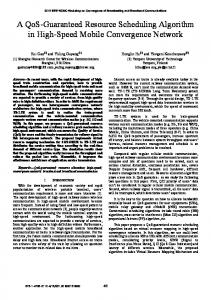
The probe forwarding mechanism obeys the following set of rules: 1) At each interface of a node, the probe with the same cid could only appear once, whether received or forwarded 2) When a node receives a probe with the same cid of the probe it has generated, it will discard that probe. 3) It is possible for a node to receive and forward a probe, which has the same cid with the one it received before. But it must be forwarded to a different interface. 4) If the destination is not within DomainN(v) and v has sent probes to all the Edges of DomainN(v), no probes with the same cid should be sent back to DomainN(v). The probe forwarding mechanism is illustrated in Fig. 1 with N=3.
c l
...
} } else { if v never generate a probe with same cid { record the probe if t ∈ DomainN(v) { Try to find a shortest eligible path from v to t if such a path exists { sent probe to t }else { calculate the shortest eligible path to the Edges of DomainN(v) and then send the probe to all the eligible Edges} }else { calculate the shortest eligible path to the Edges of DomainN(v) and then send the probe to all the eligible Edges } } }
Dom ai n( k) Domain(k)
k
e
d
Discard the probe Record the interface and cid } else { Forward the probe to the next node defined in l(m1~mN) Record the interface and cid}
r p
f
g
w
o n
Fi g 1. An exam pl e when N=3
Figure 1. Probe forwarding mechanism with N=3.
Fig. 1 shows the 3-degree Domain of a node k. Node k has the link-state information of all the links within DomainN(k). Nodes l, p and n are the edges of DomainN(k). Suppose there is a request in node k destined for a node t outside of DomainN(k). Node k will send probes to the edges of DomainN(k): l, p and n. We also assume that the destination t is not within DomainN(l). When a probe arrives at node l, l will generate new probes and send them to the edges of DomainN(l). The probes sent to the edges of DomainN(l) which are not within DomainN(k) will be helpful in probing the network. On the other hand, the probes sent to the edges of DomainN(l) which are within DomainN(k) will not contribute to the probing process. Therefore, probes need not be sent to these nodes and we can prune these useless probes with the following strategy. The edges of DomainN(l) that are in DomainN(k) are nodes k, r, e, w and o. Certainly, l will not send a probe back to k who is the source node. l would know the distance between k and r is two hops (through d, a second-degree neighbor of l), which is less than N (N = 3 in this example). Therefore, l will not send a probe to r. As for nodes w and o, let us suppose a probe heading for w or o has arrived at node n. Similarly, from the link-state information of nodes f and g, node n would know that w and o are second-degree neighbors of k and will discard these probes. The operation performed at node v when it receives a probe can be described by the following algorithm: Probe (cid, s, k, t, QoS(Bandwidth=B, Delay=D), D’, l(m1~mN))
arrives at node v if v ≠ mN { if v never sent probe with same cid to the next node which is defined in l(m1~mN) { if t ∉ DomainN(v), k is set, and the distance between k and mN is less than N hops {
D. Acknowledgment and Resource Reservation RSVP [7] is used to reserve the resources before establishing the connection. The path taken by the first probe that arrives at the destination is called a “tentative path” which will be considered for transmitting the data. After the destination receives the first probe, it will send an acknowledge message back to the source to acknowledge the probe has arrived at the destination. The acknowledgment is similar to the probe except: D’ becomes the accumulated delay of each node in the acknowledge message to the destination; k is not needed; and the path information l(m1~mN) is filled in reverse order. When each up stream node receives the probe, it will increase the accumulated delay with the delay of the link from which the acknowledgement was sent. If the current accumulated delay and the bandwidth of the link still satisfy the QoS requirement, the node will forward the acknowledgement to the next node according to the path information in the acknowledgement or in the local database (depending on whether it is the node that generated the probe or not), record the id of the downstream node and reserve the bandwidth for the acknowledgement. Otherwise, it will generate a failure notice to the downstream nodes to release the bandwidth that has been reserved for the acknowledgement. When the source receives the acknowledgement, the connection setup is complete and transmission begins. IV.
SIMULATION RESULTS AND ANALYSIS
In the worst case, the message overhead of our algorithm is O(e + l ) where e is the number of links in the network and l is the length of the tentative path. If we regard the probe processing time at each node as one unit, then the time overhead of our algorithm is O(2l ) . However, the performance of our algorithm varies in different network
1735
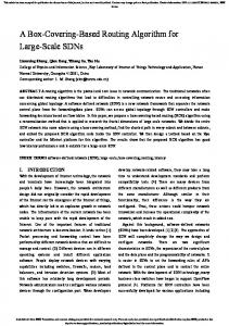
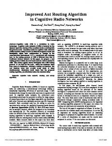
topologies. To obtain the best performance, appropriate value of N should be selected according to different network topology. Simulations were performed in two network topologies, Standard ISP network and a 32-node network as shown in Figs. 2 and 3, respectively. In our simulations, each link is duplex and has a capacity of 155Mbps. The delay of a link varies from 0.375ms to 0.625ms. All simulations were run for 2000 connection requests. The bandwidth requests are uniformly distributed between 64Kbps and 1.5Mbps. The delay requests are uniformly distributed between 6ms and 8ms.The simulation results are shown in Fig. 4 – Fig. 11.
ISP and 32-node network, the greater the N, the smaller the probe overhead. This is due to the fact that when N is large, our algorithm behaves more like source routing algorithm and when N is smaller, our algorithm behaves more like flooding. Message overhead is the sum of probe overhead and LSP overhead. We should select appropriate value of N for each network to keep the message overhead constant when the number of QoS requests is increased. However, the appropriate value of N is dependent on the network topology and can only be determine from simulations. In general, the value of N should not be too small (like N=2 in Fig. 4),
Figure 2. Network Topology of Standard ISP.
Figure 4. Overhead on Standard ISP Topology, N=2.
Figure 3. 32-node Network Topology.
Our algorithm is compared with flooding for performance evaluation. The message overhead is defined as the number of messages generated when a QoS request is admitted into the network. It is the sum of the overhead induced by the probing process and the overhead induced by LSP update, which are shown in the figures as Probe Overhead and LSP Overhead, respectively. Our link-state information update policy is periodical-based and trigger-based. Therefore, LSP overhead mostly depends on how much of the link-state information has changed. When the number of QoS requests is small, the linkstate information changes slightly and the LSP overhead is small. When the number of QoS requests is increased, more bandwidth is reserved and the link-state information changes dramatically. Therefore, the LSP overhead becomes large. Besides the number of QoS requests, the value of N and the network size also influence the LSP overhead significantly. In a large network and with a large N, each node’s LSP will be sent to more nodes resulting in larger LSP overhead. The LSP overhead is largest when all three parameters: N, network size and the number of QoS requests are large. On the other hand, the probe overhead remains the same when QoS requests increase. This is due to the fact that probe overhead is only affected by N and the network size. In the 32-node network topology, the number of nodes and links are greater than those in the Standard ISP topology. Therefore, the probe overhead in the 32-node network is greater than the Standard ISP network while N remains the same. However, for both the Standard
Figure 5. Overhead on Standard ISP Topology, N=3.
Figure 6. Overhead on Standard ISP Topology, N=4.
otherwise the probe overhead will be large. The value of N should not be too large either (like N=5 in Fig. 9.), otherwise the LSP overhead will be large when the number of QoS requests is increased. The simulation results of request admission ratio are shown in Figs. 10 and 11. The request admission ratio is defined as: the ratio between the number of QoS requests admitted into
1736
the network and the total number of QoS requests. For the Standard ISP network and 32-node network topologies, the request admission ratios of our algorithm are almost identical to flooding with a small degradation when the number of QoS request is increased. The degradation is due to the fact that there is not enough bandwidth to be reserved.
Figure 11. Request Admission Ratio on 32-node Network Topology.
V.
Figure 7. Overhead on 32-node Network Topology, N=3.
CONCLUSION
In this paper, we proposed a new QoS routing algorithm with domain link state information maintenance. The algorithm is an integration of source routing and distributed routing. The concept of “Domain” is used to reduce the message overhead of probing and link-state information update. Each node maintains the link-state information within its N-degree Domain and uses it to calculate the eligible path to the destination. The performance of our algorithm depends on the network topology and the value of N. With appropriate N, our algorithm can significantly reduce the message overhead induced by the probing process and link-state information update while maintaining high request admission ratio. REFERENCES
Figure 8. Overhead on 32-node Network Topology, N=4.
Figure 9. Overhead on 32-node Network Topology, N=5.
Figure 10. Request Admission Ratio on Standard ISP Topology.
[1]
A. Shaikh, J. Rexford, and K. G. Shin, “Evaluating the impact of stale link state on quality-of-service routing,” IEEE/ACM Transactions on Networking, Volume: 9 Issue: 2, April 2001, Page(s): 162–176. [2] R. Guerin and A. Orda., “QoS-based routing in networks with inaccurate information: Theory and algorithms,” Infocom 97, April 1997. Page(s): 75 -83 vol.1. [3] D. H. Lorenz and A. Orda., “QoS routing in networks with uncertain parameters,” Infocom 98, March 1998. Page(s): 3 -10 vol.1. [4] S. Chen and K. Nahrstedt, “Distributed QoS routing in high-speed networks based on selective probing,” University of Illinois at UrbanaChampaign, Tech. Rep., 1998. [5] S.-K. Kweon and K. G. Shin, “Distributed QoS routing using bounded flooding,” University of Michigan, Ann Arbor, CSE Tech. Rep. CSETR-388-99, 1999. [6] D. Ghosh, V. Sarangan, and R. Acharya, “Quality-of-service routing in IP networks,” IEEE Transactions on Multimedia, vol. 3, Issue: 2, June 2001. Page(s): 200 –208. [7] L. Zhang, S. Deering, D. Estrin, S. Shenker, and D. Zappala, “RSVP: a new resource ReSerVation Protocol,” IEEE Network, Sept. 1993. Page(s): 8 –18. [8] G. Apostolopoulos, R. Guerin, S. Kamat, and S. K. Tripathi, “Quality of service based routing: A performance perspective,” Proc. SIGCOMM (Vancouver, BC, Canada), Sept. 1998. Pages: 17 – 28 [9] S. Chen and K. Nahrstedt, “Distributed QoS routing with Imprecise State Information,” Proc. Of ICCCN’98, Louisiana, Oct. 1998. Page(s): 614 –621. [10] Z. Wang and J. Crowcroft, “QoS routing for supporting multimedia applications,” IEEE J. Select. Areas Comm., Sept. 1996. Page(s): 1228 –1234. [11] Zhi Li; Mohapatra, ICC 2002. IEEE International Conference on P. Communications, vol. 2 , 2002 Page(s): 1259–1263. [12] Alberto Leon-Garcia and Indra widjaja, Communication Networks: Fundamental Concepts and key Architectures., McGraw-Hill, 2000. Page 497-498.
1737