2015 International Conference on Circuit, Power and Computing Technologies [ICCPCT]
A Quantitative and Comparative Performance Evaluation of PVModels on PSPICE Platform Soubhagya Kumar Dash
R. Akhil Raj
Dr.Savita nema
Dr. R. K. Nema
Research Scholar, EED, MANIT Bhopal M.P. India
[email protected]
Research Scholar, EED, MANIT Bhopal M.P. India
[email protected]
Professor, EED, MANIT Bhopal M.P. India
[email protected]
Professor, EED, MANIT Bhopal M.P. India
[email protected]
Abstract—despite of the abundant resource potential and availability of conventional resources like oil and gas in many countries is moving toward the sustainable energy like solar power. Even though these country’s has a substantial amount of installed capacity largely based on renewable energy like hydropower, but these resources yield fluctuates greatly during the drought season, forcing to rely on expensive emergency thermal units which again considerably affects the environmental balance but by implementing solar power resources substantial difference can be brought in the environmental circumstances. This paper presents simulation and study of PV cells using the generic model on PSPICE platform. Using PSPICE circuit simulator voltage and current variation can be verified under different a set of condition. Diode based models are used to conduct the studies which are classified on the basis of number of diodes. This paper provides a comparative behavioral study of different models under varying condition of temperature, diode parameter, solar insolation, and etc. This study helps in sketching out the performance evaluation under different circuit topology and control strategy. Keywords— Circuit Simulator; PSPICE; Photovoltaic (PV) array; Single diode model; Two diode model. I.
INTRODUCTION
The industrializing world demands energy, to fulfill this increasing demand of energy researchers are striving to exploit the hidden vast potential of renewable energy sources. With the rising concern of environmental effect caused by the immense usage of conventional sources of energy obliging us for alternative energy source. The rapid fall in the cost of solar PV modules makes it as an important renewable source in the global energy scenario. PV energy is most popular of renewable sources because of easy installation in unused space, low maintenance and eco-friendly. Apparently a high penetration of PV system in electricity generation evidence that the PV system is anticipated to be largest energy sources. For grid connected system, it demands of high level of power conversion, the non-optimal MPP method contrasts with it. Thus modeling of PV cell is vital for PV system perusal. Various literatures are available for simulation of PV models with parameterization [1]-[6].Simulation of a single diode model is based on the assumption that the recombination loss in depletion region is absent. The recombination loss can be more precisely consider in two diode model [7]-[8]. PSPICE has advantages as wider commercial component
978-1-4799-7075-9/15/$31.00©2015 IEEE
library, multiple plot view, availability of components with manufacturer specification, easy circuit implementation [9][10]. In this paper a comparative study and analysis of diode based PV model (Two diode and Single diode) described by five model parameters (IPh, Is, N, Rs and Rsh) which are related to different circuit parameters and atmospheric conditions such as solar insolation and temperature. These diodes based PV models are implemented in PSPICE. II.
PHOTOVOLTAIC (PV) CELL MODEL
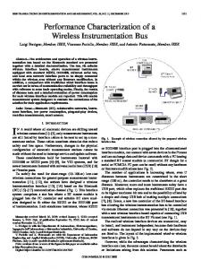
PV arrays are made up with a series/parallel combination of PV solar cells. PV cell is derived from the physics of the PN junction diode and it reflects the performance of the cell. The single diode model is given in Fig.1. The PV cell output voltage (typically 0.5 to 0.8V) is a function of the photocurrent; it is determined by the load current depending upon the solar insolation and temperature. Polycrystalline silicon cells are represented by an exponential equation [11][12].Two diode model is more realistic when recombination losses are considered. The equivalent circuit of two-diode model is shown in Fig.2. The voltage–current characteristics of solar PV cell for the p–n junction diode are described by the following Eq. (1) to Eq. (5).
Fig. 1. Equivalent Circuit of single diode model
Fig. 2.
. Equivalent circuit of two-diode model 1
2015 International Confeerence on Circuit, Power and Computing Technologiess [ICCPCT] Where, 1
2 1
,
3 4 5
the recombination process occcurs via band to band, trapassisted and auger for level of injection. The foundation of the simple diode equation uses deffinite assumption about the cell. Practically the ideal diode doees not follow the simple diode equation so the ideality factor provides p an approach to relating them by considering the numbeer of carriers. The ideal value of ideality factor (N) for silicon PV P cell is ‘1’ but practically its lies between 1&2.It is also knnown as emissivity factor. The effect of variation in idealityy-factor is obtained by nested sweep variable N and resultt shows that the open circuit voltage VOC increases as revealed in Fig.5.
Where IPh is the photo generateed current, which depends upon solar insolation, (I01, I02,VT1,V VT2,N1 and N2) are the reverse saturation current, terminal voltage and ideality factor of diode 1 and 2 respectively, ns is nuumber of cells are connected in series, and q, k, and T are thhe electron charge (1.602 10-19C), Boltzmann constant (1.3811 10-23 J/K), and junction temperature in Kelvin (K) respectiveely. III.
CHARACTERISTCS OF SOLAR R PV CELL
The V-I characteristics of a solar PV P cell are derived from the V-I characteristics of the diode in the darkness with increase in photo generated current. The major m effect of the light, it will shift the V-I characteristics dow wn into the fourth quadrant where power can be extracted froom the diode. The schematic of two-diode as shown in Fig.33 is simulated for obtaining the PV cell characteristics as depicted d in Fig.4. .
Fig. 5. Variation in iddeality factor
2.
Variation of Reverse saturation s current Another important parameter p is reverse saturation current (IS) of diode. Physicallly, it measures the "leakage" of carriers across the junction (p--n)when it is operates in reverse bias. Recombination in neutrall region occurs on either side of junction due to leakage of carrier. The major effect of variation in saturation currentt is obtained by nested sweep variable IS. From the simulatioon result it can be seen in Fig.6 that the open circuit voltage decreased by variation of the reverse saturation current.
Fig. 3. Schematic of two diode moddel
Fig. 6. Variation in reeverse saturation current
B. Fig. 4. VI and PV characteristics of ceell
IV. A.
EFFECT OF VARIATION IN MODELL PARAMETERS
Variation of Diode Parameters Variation of Ideality –factor The ideality factor of a diode that describes how to closely the diode behavior follows the ideal diode equation. In case of the ideal diode equation, it assumes all
Variation of Loss Com mponent
There are two powerr loss components in solar PV model i.e. series resistance annd shunt resistance. Presence of series resistance in a solar PV P causes the flow of current through emitter and base and the contact resistance between the silicon and metal contacct. The major issue of series resistance is to reduce the fill factor and short-circuit current due to high values of series ressistance. Due to the presence of
2015 International Confeerence on Circuit, Power and Computing Technologiess [ICCPCT] shunt resistance, it causes power loss due to poor design of solar cell and manufacturing defects. Variation of Series Resistance (Rs) The major effect of series resistancce is to reduce the short-circuit current andfill factor (FF). Athiggh values of series resistanceit reduces the power output of a cell/module/array. The FF is defined as the ratio of the maximuum power from the solar cell to the product of open circuit voltaage (Voc) and short circuit current(Isc). It is also known as curvee factor and given by Eq. (6). 1.
6 Where VMPP and IMPP are the maxiimum power point at voltage and current. The effect of variaation on different values of Rs is simulated under PSPICE E by main sweep variableV1 (control voltage) and nestedd sweep variable Rs(global parameter) as depicted in Fig.7. It I observed that it generates more output power and higher FF F for low value of
C. Effect of Variation in Enviroonmental Parameters 1. Variation of Insolationn (λ) In solar PV the photo generated current (IPh) is t which is given by depends upon insolation and temperature, the following equation. 298
7 100 C is the temperature coefficient whereKi=0.0017 A/◦C of cell's short circuit currentt and λis the solar insolation (W/m2). Eq. (7) dictates thatt at constant temperature, IPhis r current ‘ISC’ of a solar PV directly proportional toλ. The rated cell is 4A at standard temperrature condition. The values of these rated currents are 3A, 2A A and 1A will represent as 75%, 50% and 25% of solar insolatioon. The effect of variationn in solar insolation is simulated using ‘current source’ Iph as nested n sweep variable. It can be observed from the simulation result r that, when solar insolation reduces both VOC and ISC are deecreases as depicted in Fig.4. 2.
Variation of Temperatture (T)
Solar PV panels aree like semiconductor devices, which are sensitive to tempeerature.Increase in temperature reduces the band gap of semicoonductor devices and effects the parameters of semiconductor material. m In a solar PV, mostly open-circuit voltage(VOC), shhort circuit current (ISC) and saturation current (IS) are affeccted by variation of temperature. The reverse saturation current of diode varies as cubic power and expressed as Eq. (8). Rs.
1 Fig. 7. Variation in series resistance
2.
Variation of Shunt Resistance (Rsh) In presence of low shunt resistancce, induces power losses in solar cells/modules due to an alteernate current path for the photon current. Therefore it redduces current and voltage of the solar PV panel. The major effect of a shunt resistance is critical at low insolation levels, in view of the fact that it will generate less photon current.The effect of variation on different values of Rsh is simulated underr PSPICE by main sweep variable V1 (control voltage) and nestted sweep variable Rsh(global parameter) as shown in Fig.8. It I observed that it induces more output power loss and low FF F for low value of Rsh.
Fig. 8. Variation in shunt resistancce
.
8
Where: ‘Is’is diode reverses saturation current, ‘Tnom’is nominal temperature, ‘Eg’ is band gap energy of theseemiconductor and ‘Vt’ is the thermal voltage The impact of variatioon in temperature is revealed in Fig.9.From the simulation ressult it is observed that power output and VOC decreases and ISCincreases of a solar cell with increasing temperature.
Fig. 9. Variatioon in temperature
2015 International Confeerence on Circuit, Power and Computing Technologiess [ICCPCT] V.
CHARTERSTICS OF PV MODU ULE / ARRAY
Solar PV modules are obtained by interconnecting of s and parallel. several solar cells, which are connected in series It gives larger output voltage and current (hhence large output power) than a single cell.Now a day’s PV modules are also 4 and 72V.For designed for higher output voltage of 48V simulation of a PV module, the voltage–currrent relationship of PV cell is expressed as Eq. (9). I = n n
P
I
S 2
P
I
− n
Ph
⎛ ⎜⎜ exp ⎝
(N
I
P
2
S 1
qv KT
⎛ ⎜⎜ exp ⎝
)n S
(N
qvv KT T 1
⎞ − 1 ⎟⎟ − ⎠
)n S (V
condition (STC). Here param meters based comparison with single diode are performed using graphical and tabular analysis. The graphical anaalysis of single diode model simulated on PSPICE simulatoor is shown in Fig.12 to Fig. 19 [7]. Two diode model is an apppropriate solution for change in
⎞ − 1 ⎟⎟ − ⎠
+ IR R sh
s
)
Fig. 12. Variatioon in ideality factor
Fig. 10. Characteristics of PV Moduule
In this PV module 36 solar cellls are connected series(ns) and one current path is considered i.e. np=1 and ns=36. For simulation of a PV module seriess connected cellsns are united with ideality factor N. For PV array, PV modules are connnected together in order to achieve higher voltage and output power than a single PV module. For simulation of array 722 solar cells are connected series(ns) and two current path is considered i.e. np=2.The PSPICE simulation result of modulle and an array are revealed in Fig. 10 and Fig. 11 under varyinng insolation. This result shows that both short circuit currrent ISC and VOC increases according to variation of insolattion hence output power increases.
Fig. 13. Variation in reeverse saturation current
environmental condition as it compensates for recombination losses. It is clear from the annalysis that for each parameter change in both models under STC, two diode model gives near to practical value with respectt to single diode model. At low voltage the recombination loosses are high that leads to inaccurate results in a single diode model.
Fig. 14. Variation in Series Resistance Fig. 11. Characteristics of PV Arraay
VI.
GRAPHICAL AND TABULAR ANALYSIS
In this section single diode modeel is simulated on PSPICE platform using diode D1N4002 unnder standard test
2015 International Confeerence on Circuit, Power and Computing Technologiess [ICCPCT]
Fig. 15. Variation in Insolation Levvel
Fig. 19. Characteristics of PV array baased on single diode model
A Parametric based tabular analysis a is tabulated below from Table 1 to Table 7. VII.
Fig. 16. Characteristics of PV module based onn single diode
Fig. 17. Characteristics of PV array based on sinngle diode model
CONCLUSION
In this research a comprehhensive study on solar PV cell (two diode and single diodde) with variation in circuit parameter and environmentall condition is performed. The models developed on PSPICE platform are to achieve similar PV and VI characteristics too the graphs provided in the datasheet by the manufactureer of solar system. PSPICE is incorporated with componentt library that has component configuration similar to devicees available in the market which helps to develop a model whicch has identical characteristic to the physical model. The curvess of two diode model resembles to the desired results which helps h to study the performance and behavior close to real scenario.Anelaborated s study is conducted ontwo diode basedd PV model analyzed by five model parameters (IPh, Is, N, RsandRsh).The two diode model proves to be suitable for low temperature t and insolation level because the sun pattern starrts with low insolation in the morning and in the evening. Soo the performance evaluation of two-diode model is more accurate. a It is very close to practicalresults of solar PV system for different circuit u insolation levels. The topology and control strategy underlow two-diode model is superior to single diode model under partial shading condition of o solar PV system.PSPICE simulator avoids the complexxity due to increase number of parameter which results unw wanted iteration and increase computational time. E VIII. REFERENCES [1]
[2]
Fig. 18. Characteristics of PV module based onn single diode
[3]
Weidong Xiao; Edwin, F.F.; Sppagnuolo, G.; Jatskevich, J., "Efficient Approaches for Modeling and a Simulating Photovoltaic Power Systems," Photovoltaics, IEEE Journal J of , vol.3, no.1, pp.500,508, Jan. 2013. Ishaque, Kashif; Salam, Zainaal; Taheri, Hamed, "Simple, fast and accurate two-diode model for photovoltaic modules." Solar Energy Materials and Solar Cells, vol.955, no. 2,pp.586,594, 2011. Kumar, A. V. Pavan; Alivelu M. M Parimi; K. Uma Rao, “A Comparative Design of PV cell in Study of Model Based MATLAB/Simulink/Simscape.”” International Journal of Advanced Trends in Computer Science andd Engineering, Vol. 3, no.1, pp. 37 – 42, 2014.
2015 International Conference on Circuit, Power and Computing Technologies [ICCPCT] [4]
Wangnianchun; Wu MeiYue; Shi GuoSheng, "Study on Characteristics of Photovoltaic Cells Based on MATLAB Simulation," Power and Energy Engineering Conference (APPEEC), 2011 Asia-Pacific, vol., no., pp.1-4, 25-28 March 2011. [5] Sahoo, N.C.; Elamvazuthi, I.; Nor, N.M.; Sebastian, P.; Lim, B. P., "PV panel modelling using Simscape, "International Conference on Energy, Automation, and Signal (ICEAS), pp.1-4, 28-30 Dec. 2011. [6] Shekoofa, O.; Taherbaneh, M., "Modelling of Silicon Solar Panel by MATLAB/Simulink and Evaluating the Importance of Its Parameters in a Space Application," 3rd International Conference on Recent Advances in Space Technologies, RAST '07., pp.719-724, 14-16 June 2007. [7] Ishaque, Kashif; Salam, Zainal; Taheri, Hamed, "Accurate MATLAB simulink PV system simulator based on a two-diode model." Journal of Power Electronics, vol.11, no. 2, pp.179, 187, 2011. [8] C. Sah, R. N. Noyce, and W. Shockley, “Carrier generation and recombination in p-n junctions and p-n junction characteristics,” in Proc. IRE, Vol. 45, No, 9, pp. 1228-1243, 1957. [9] Nema, R. K.;Nema,Savita; Agnihotri, Gayatri, "Computer simulation based study of photovoltaic cells/modules and their experimental verification."International Journal of Recent Trends in Engineering 1,no. 3, pp.151-156, 2009. [10] Rathee, Reena; Khanna, Vandana; Das, B.K., “Spice based modelling and simulation to study the effects of partial shading on PVarray characteristics.” International Journal of Engineering Science Invention, vol.2, no.5, pp. 68-73, May.2013. [11] Nema, Savita; Nema,R. K.; Agnihotri, Gayatri, "MATLAB/Simulink based study of photovoltaic cells/modules/array and their experimental verification."International journal of Energy and Environment,vol.1, no. 3,pp.487,500, May 2010. [12] Bhuvaneswari, G.; Annamalai, R., "Development of a solar cell model in MATLAB for PV based generation system," Annual IEEE IndiaConference (INDICON), pp.1-5, 16-18 Dec. 2011.
2015 International Conference on Circuit, Power and Computing Technologies [ICCPCT] Table1.
APPENDIX-I
Variation in Ideality Factor (N) 1
VOC( V) 0.63
ISC( A) 4
1.5
0.88
4
0.65
2 2.5 3
1.14 1.35 1.38
4 4 4
0.86 1.05 1.1
Single diode Model VMPP IMPP (V) (A) 0.44 3.75
(W) 1.65
VOC( V) 0.55
ISC( A) 4
3.76
2.45
0.8
4
3.77 3.8 4
3.25 3.97 4.4
1.03 1.24 1.28
4 4 4
Two diode Model VMPP IMPP (V) (A) 0.42 3.7 5 0.62 3.75 5 0.83 3.77 1.02 3.79 1.05 3.9
(W) 1.572 2.343 3.129 3.866 4.095
Table 2 Single diode Model VMPP(V) ISC (A) 4 0.55
Variation in Reverse saturation current (IS)
VOC(V)
10 A
0.8
1 A
0.92
4
50nA
1.06
4
Two diode Model VMPP(V) ISC (A) 4 0.5
IMPP (A) 3.6
VOC(V)
0.67
3.65
0.82
4
0.62
3.67
0.8
3.7
0.96
4
0.77
3.68
0.693
IMPP (A) 3.66
Table 3 Variation in series resistance (RS)
VOC( V) 1.12 1.12 1.12
0.1 0.01 0.001
ISC( A) 4 4 4
Single diode Model VMPP( IMPP (A) V) 0.625 3.2 0.84 3.80 0.86 3.9
0.446 0.712 0.748
VOC( V) 1.025 1.025 1.025
ISC( A) 4 4 4
Two diode Model VMPP( IMPP (A) V) 0.575 3.25 0.8 3.68 0.825 3.7
0.42 0.72 0.745
VOC( V) 1 1.02 1.02
ISC( A) 4 4 4
Two diode Model VMPP( IMPP (A) V) 0.8 3.05 0.81 3.7 0.83 3.8
0.61 0.735 0.773
Table 4 Variation in shunt resistance (RSh)
VOC( V) 1.08 1.12 1.12
1 10 1000
Single diode Model ISC( VMPP IMPP (V) (A) A) 4 0.82 3.04 4 0.83 3.79 4 0.85 3.82
Variation in Temperature (T) 270
0.577 0.702 0.724 Table 5 Single diode Model VMPP(V) VOC(V) ISC (A) 1.09 4 0.79
IMPP (A) 3.15
VOC(V) 0.9
Two diode Model VMPP(V) ISC (A) 4 0.75
IMPP (A) 3.1
0
1.12
4.05
0.81
3.17
0.95
4.05
0.77
3.68
870
1.15
4.1
0.825
3.18
1
4.1
0.8
3.7
57
2015 International Conference on Circuit, Power and Computing Technologies [ICCPCT] Table 6 Single diode Model VMPP(V) VOC(V) ISC (A) 1.13 4 0.86
Variation in Insolation (λ) 1000W/m2
NS
NP
36
1
72
2
.
IMPP (A) 3.74
VOC(V) 1.02
Two diode Model VMPP(V) ISC (A) 4 0.85
IMPP (A) 3.76
2
750W/m
1.08
3
0.85
2.82
0.99
3
0.83
2.75
500W/m2
1.02
2
0.82
1.89
0.96
2
0.8
1.89
250W/m2
0.96
1
0.8
0.9
0.9
1
0.76
0.9
Variation in Insolation (λ) 1000 750 500 250 1000 750 500 250
VOC( V) 18.2 18 17.5 16.8 37.9 37 36.5 35
ISC( A) 4 3 2 1 8 6 4 2
Table 7 Single diode Model IMPP VMPP (V) (A) (W) 15.5 3.774 58.5 15.2 2.828 43 15 1.866 28 14.6 0.890 13 32.5 7.446 242 32 5.625 180 31 3.774 117 30.2 1.887 57
VOC( V) 17.5 17.2 16.9 16.2 36.5 35.8 35 33.8
ISC( A) 4 3 2 1 8 6 4 2
Two diode Model IMPP VMPP (V) (A) 14.9 3.758 14.5 2.862 14.2 1.901 13.5 0.962 31 7.580 30.4 5.657 30 3.733 29 1.862
(W) 56 41.5 27 13 235 172 112 54