5DARPA-MTO, Arlington, VA 22203-1714. Abstract - A miniature non-uniform copper-air rectangular coaxial line with the inner conductor supported by periodic.
1393
Modeling, Design, Fabrication, and Performance of Rectangular g-Coaxial Lines and Components D. S. Filipovic', Z. Popovic', K. Vanhille' M. Lukic' S. Rondineau' M. Buck' G. Potvin2 D. Fontaine2, C. Nichols3, D. Sherrer3, S. Zhou3, W. Houck3, D. Fleming3, E. Daniel4, W. Wilkins4, V. Sokolov4, and J. Evans5 Department of Electrical and Computer Engineering, University of Colorado, Boulder 80309-0425 2~~~~~ 2BAE Systems, Nashua, NH 03060 3Rohm and Hass Electronic Materials LLC, Blacksburg, VA 24060 4Mayo Clinic, Rochester, MN, 55905 5DARPA-MTO, Arlington, VA 22203-1714 Abstract - A miniature non-uniform copper-air rectangular coaxial line with the inner conductor supported by periodic dielectric straps is demonstrated. The overall height of the line is 310gm with the outer conductor cross-section being 250gmx250gm. The measured loss is 0.22dB/cm at 26GHz, while the isolation between two parallel lines with a center-to-center separation of 700gm is better than 60dB. Several quasi-planar components are designed and fabricated on the same wafer, and presented here are a branch-line hybrid and a transmission line resonator. The through and coupled port transmissions for the hybrid at 26GHz are -3.25dB and -3.35dB respectively, with phase misbalance below 0.2°. The transmission line resonator has an unloaded Q-factor of 110 at 25GHz.
their practical implementation. The performance of the basic transmission lines, branch-line hybrid, and transmission line resonator are compared with the developed models. The paper is organized as follows: a brief discussion on modeling and fabrication is given in Section II, followed by the performance characterization of a basic recta-coax line in Section III. Several g-coaxial components are presented in Section IV.
Index Terms - Branch line hybrid, Coaxial line, Computer aided design, Transmission Line Resonator. I. INTRODUCTION
Recent advances in micro-electromechanical systems (MEMS) fabrication techniques [1-3], including surface and bulk micromachining, provide ample opportunities for the use of small rectangular coaxial lines (RCL), also known as recta-coax. Highly integrated designs and assembly of non-dispersive, high-isolation lines, components, and sub-systems operating in the millimeter and sub-millimeter bands are becoming feasible. A number of novel recta-coax structures with heights from 50gm to 400gm have already been reported. For instance, air-filled RCLs built using different variations of surface micromachining are demonstrated in [4]. Very promising results with somewhat higher losses than the theoretical predictions are obtained. Branch line hybrids [5, 6] and filters [7], are recent examples of miniature RCL components designed to operate up to V-band. These lines and components are typically analyzed using 3D finite element solvers. In this paper, we discuss modeling and design of miniature irnhomogeneous copper recta-coax lines and components as well as a novel sequential microfabrication process [8] that enables
0-7803-9542-5/06/$20.00 ©2006 IEEE
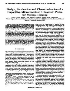
Fig. 1. Sketch of the ~i-recta-coax line. Structural parameters are: {w0,
ho, wi, hi, Lp, Ls, hs, Lh, Wh} = (0.25, 0.25, 0.1, 0.1, 0.7, 0.1, 0.015, 0.2, 0.1 } mm; 8r=3.7, and tan&0.05.
II. MODELING AND FABRICATION
A. Modeling Challenges andApproach Analysis of miniature rectangular coaxial lines and components is a challenging task. The issues can be argued from geometrical and computational perspectives. Multi-layered configuration, the combination of small and large structural features, homogeneous and irnhomogeneous cross-sections, sharp corners and roughness, misalignment of structural layers, the need for release holes, etc. are just a few examples of geometrical concerns that must be considered. The analysis method needs to accommodate easy 2D and 3D
1394
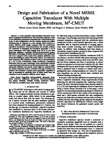
formulations and solutions of closed domain structures. However, the effects of the release holes, particularly radiation leakage through those must be also modeled. Also, the computational domain contains both small and large features, materials of different dielectric constants and high/low aspect ratios, and a combination of rough and smooth surfaces. All these demands place severe restrictions on the choice of modeling tools. Finally, a capability of easy definition of excitations, boundary conditions, material parameters, and extraction of performance parameters must be also accounted for. To address all these issues, a modeling approach (see Fig. 2) combining robust 2D and 3D eigenanalysis (EA) and driven finite element method (FEM) formulations within Ansoft's High Frequency Structure Simulator (HFSS') and quasi-static (QS) singly and doubly connected Schwartz-Christoffel conformal mapping (SCCM) [9] are utilized.
tan6=0.05). As shown in Fig. 1, the release holes in the side (100gmx75gm) and top walls (200gmxlOOgm) are placed in the regions between the straps. HFSS and SCCM are used to fully characterize the performance of the line. Electrical effects of potential fabrication issues such as strap parameters including the protrusion into the vertical walls, offset layers, under/over etching, surface roughness are also investigated (see Fig. 4). It is found that the performance of a line built within the limits of our fabrication tolerances is almost the same as the performance of a perfectly fabricated structure.
Finite Element Method Conformal Mapping 2D FEM
Quasi-static (QS)
2D Quasi-static
Full-wave (FW)
Eigenanalysis (EA)
Determination of ZO, y Efficient for time and memory Adequate modeling of sharp corners Easier convergence with fine geom. details Determination of higher order modes (EA)
* * * *
3D FEM
Eigenanalysis (EA)
PDE CEM choice for closed structures Higher order expansion, exact BCs Freedom in modeling 3D structures Robust modeling of inhomogenities FE-BI for antenna design
Fig. 2. Modeling approach followed in this work.
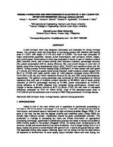
B. Fabrication Recta-coax lines and components are fabricated using a new sequential microfabrication process described in [8]. As in surface micromachining, the recta-coax structures are built up layer by layer by depositing a uniform copper stratum (layer 1), and a sequence of strata comprised of photo-resist and copper (layers 2, 4, and 5). The polymer support for the inner conductor is a part of the 3rd layer. The heights of layers 1-5 are {10, 75, 100, 75, 50} gim, respectively. Once the structure is built, the resist is drained through holes in the top and side walls (see Fig. 1). These openings are referred to as release holes. A scanning electron microscope (SEM) photo of a part of the fabricated wafer is shown in Fig. 3. Shown in the picture are different recta-coax lines, calibration structures, test sets for isolation, and several different cavity resonators. The components are built on a 15cm diameter and 1mm thick high resistivity Si wafer, however, other substrates may also be used. III. RECTA-COAX LINE Several 250gm tall rectangular and square 50Q coaxial lines are designed and fabricated. They are composed of five structural layers forming the inner and outer conductors. The
inner conductor is supported by periodically (700gm) spaced 15gm tall and 100gm wide dielectric support straps (e =3.7,
Fig. 3. SEM photograph of a portion ofthe fabricated wafer showing a number of coaxial lines with various separation distances, as well as portions of cavity resonators (larger areas in the photo). The 25Ox3OOm feed ports (launches) into the lines are visible as rectangular coaxial openings at the end of each line/component. The holes in the top and side walls are used for releasing the photoresist. The metal posts seen in the photo do not have any electrical effect.
d
.I
I
I
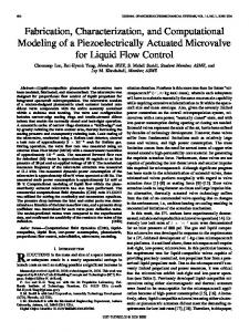
Fig. 4. Sketches of several geometries used to study effects of: dielectric straps (top left); under/over etching (top right); misaligned layers (bottom left); and surface roughness (bottom right).
As shown in Fig. 5, a 10% misalignment of stratum 3 increases the line attenuation by about 300, decreases the characteristic impedance by 1% and barely affects the cut-off frequency of the first higher order mode. Also shown in the figure is excellent agreement between the full-wave HIFSS and QS SCCM. The results are almost indistinguishable for the
1395
characteristic impedance whereas there is a slight discrepancy for the attenuation constant. 104--
complete metal deposition can produce dangerous stress levels on the wafer, it is a risk worth undertaking particularly in light of the reduced cross-talk between neighboring lines. The measured isolation and standard deviation (a) for several test structures are given in Table I.
IM4 DtiV
TABLE I
MEASURED ISOLATION FOR TWO ADJACENT PARALLEL LINES.
100
%®* S8
|S311 [dB] |o(IS3I1)
f [GHz] 24 26 28
*0
63.0 62.5 62.7
0.83 0.89 0.57
S411 [dB] 65.2 62.5 60.9
o(5S411) 0.53 1.09 0.80
0
6
Fig. 5. Predicted effects of misaligned stratum 3 on the performance of the RCL (lower left drawing in Fig. 4). The attenuation constant ao0, characteristic impedance Z,o and higher order cut-offfo of an ideal line are 0.161dB/cm at 26GHz, 50Q, and 467.5GHz, respectively.
The measured attenuation of a 50Q line is compared with simulations in Fig. 6 showing a loss of 0.22dB/cm at 26GHz. The measurements are calibrated using external short-open-load-thru (SOLT) calibration. Shown in the same figure is the line loss at 25GHz as de-embedded from the t-coaxial transmission line (TRL) resonator measurements discussed in the next section. C
-0.05
FEK
7d
-1 0
20
22
24
2
_RO"hd n _H
28
30
Fig. 7. Simulated return loss and cross-coupling for the structure shown in the inset. The wafer layout around the 4-port test structure is modeled exactly as fabricated. Denoted are structure's ports, gold foil traces (Au), copper traces (Cu) and non-metallized silicon wafer (Si).
IV. RECTA-COAX COMPONENTS
Several passive components, including branch-line hybrids, cavity backed patch antennas, as well as cavity and transmission line resonators are fabricated on the same wafer. Here we show results for a hybrid and a transmission line resonator.
-0.1 0
*F -0.15
& -0.2 Simulated
-0.25
co
---- Measured 0 Measured: TRL Res 5
10 15 20 Frequency in GHz
Fig. 6. Measured and computed transmission of a inset is a sketch of the launch cross-section.
25 1cm
30
long line. The
Shown in Fig. 7 is the computed isolation between two lines with a center-to-center separation of 700gm. The computational model is depicted in the same figure. It was determined that the main coupling mechanism of a non-metalized layer 1 structure is through the launch opening, and that special care must be exercised for the mitigation thereof. Specifically, the coupling can increase by almost 20dB if layer 1 is not metalized. While
A. Branch-Line Hybrid t-coaxial branch-line hybrids have been demonstrated using a different fabrication technique with nickel as the structural metal and with the short metallic posts supporting the inner conductor [6,7]. Here, we followed a standard branch-line hybrid design procedure in a copper-air-polymer based RCL configuration described in previous sections. Special care was exercised in studying the effects of the release holes and dielectric support. It was found that they have a small effect on amplitude and phase balance. Measured and predicted amplitude and phase of transmission through the direct and coupled ports are shown in Fig. 8 and 9, respectively. At the design frequency of 26GHz, the measured amplitude misbalance is 0.1dB (S31=-3.35dB, IS211=-3.25dB).
1396 program. The authors acknowledge Mr. E. Adler and Mr. R. Polcawich from ARL for useful discussions on the topic.
4[
..-t 4g
0
t
1 p.
Af
..~
Q=6
r *i
A
344
LatlLh
a
20
o
e.
Gap
Rdekag ho6l
I_
IW
Fig. 8. Measured (dots) and simulated (solid) coupling to through and coupled ports. Shown in the inset is an SEM of the fabricated hybrid. 150
247
248
PFE
50-.. ,5
251
REFERENCES
0
/
Dielectric
-50 a3
S21
150o 20
24,
Freqercy ir GHz Fig. 10. Measured transmission of a transmission line resonator. Shown in inset is a 1/2 of the structure's cross-section.
31
100 r
fleikcr
... ..................... N e tkf&ri
22
24
Freqency
2
in GHz
281
30,
Fig. 9. Measured (dots) and simulated (solid) phaise at through and coupled ports. Shown in the inset is a 1/4 symmetry nnodel.
B. Transmission Line Resonator A transmission line resonator is a useful component for has a characterizing attenuation. The 2-port half-wavTe resonator has 5.77mm long inner conductor supported by ei,ght 100gm wide dielectric straps separated (center-to-cente-r) by 0.7mm. Coupling is achieved with 50tm wide capa citive gaps. The formulaeused measured IS211 is shown in Fig. 10, along with tlhehe formulae used to compute the Q-factor and line loss. AlIso shown is a cross-section of the structure. The RCL loss, e)stracted from the transmission line resonator measurements, is g ;iven in Fig. 6.
compsonentfor
V. CONCLUSION High performance copper-air t-coaxial lines and components are designed and fabricated using a novel imicrofabrication process. The obtained results are discussed in this paper. ACKNOWLEDGMENT This work is funded by DARPA-MTO under the 3D MicroElectromagnetic Radio Frequency Systems (3D-MERFS)
[1] R. Chen, "Micro-fabrication techniques," Wireless Design and Development, pp. 16-20, Dec. 2004. [2] J.-B. Yoon, B.-I. Kim, Y.-S. Choi, and E. Yoon, "3-D construction of monolithic passive components for RF and microwave ICs using thick-metal surface micromachining technology," IEEE Trans. Microwave Theory Tech., vol. 5 1, no. 1, pp. 279-288, Jan. 2003. [3] I. Jeong, S.-H. Go, J.-S. Lee, and C.-M. Nam, "High-performance air-gap transmission lines and inductors for mm-wave applications," IEEE Trans. Microwave Theory Tech., vol. 50, no.12, pp. 2850-2855, Dec. 2002. [4] E. Brown, A. Cohn, C. Bang, M. Lockard, B. Byrne, N. Vandlli, D. McPherson and G. Zhang, "Characteristics of microfabricated rectangular coax in Ka band," Microwave and Optical Tech. Lett., vol. 40, no. 5, pp. 365-368, March 2004. [5] J. Reid and R. Webster, "A 60GHz branch line coupler fabricated using integrated rectangular coaxial lines," Proc. IEEE MTT-S
Int. Microwave Symp, Fort Worth, TX, June, 2004, pp. 441-444.
[6] R. Chen, E. Brown and R. Singh, "A compact 30GHz low loss balanced hybrid coupler fabricated using micromachined integrated coax," Proc. IEEE Radio Wireless. Conf:, pp. 227-230, Sept. 2004.
[7] J. Reid and R. Webster, "A compact integrated V-band bandpass filter," Proc. 2004 IEEE AP-S Int. Symp., Monteray, CA, July 2004, pp. 990-993.
[8] D. Sherrer and J. Fisher, "Coaxial waveguide microstructures and the method of formation thereof," U.S. Patent Application Publication No. US 2004/0 263 290A1, Dec. 30, 2004. [9] T. Driscoll and L. Trefethen, Schwarz-Christoffel Mapping, Cambridge Univ. Press, 2002.