A Queueing Model for Finite Load IEEE 802.11 Random Access MAC
Recommend Documents
The IEEE 802.11 MAC [7] has become ubiquitous and gained widespread popularity as a layer-2 protocol for wireless local area networks. While efforts have ...
May 26, 2009 - transmitted to another network node, the receiver, according to a deterministic ... than the effective transmission rate, queues can build up due.
Jun 8, 2013 - q(t) denotes the number of calls in the outbound queue at time t,. ⢠o(t) is the number ..... of maximum queue lengths to call center management.
Chul Geun Park and Ho Suk Jung. Department of Information and Comm. Eng. Sunmoon ... Dong Hwan Han. Department of Mathematics. Sunmoon University.
between CSMA and TDMA, LA-MAC achieves a high channel utilization and a ... collection of MIMO Universal Software Radio Peripheral (USRP). Software Defined Radio .... to the best of our knowledge, leveraging advance capabilities of such MANET ......
design for wireless networks based on maximizing a network utility function. .... described in the previous section has several drawbacks from a practical ...
Aug 17, 2005 - An important feature of the MVA algorithm, com- pared to the ..... tween numbers with N precision bits can be performed with the Karatsuba.
major access point into the health care system. Yet primary care practices ...... Rust, C. T., N.H. Gallups, W.S. Clark, D.S. Jones, and W.D. Wilcox. 1995. Patient.
models in providing guidance on identifying patient panel sizes for medical ... approach in both managed care and fee-for-service environments including ...
develop a queueing model to help identify nurse staffing levels in hospital clinical units .... of general medical/surgical beds or correspond to one or more specific hospital ...... nyhealthcarecommission.org/docs/final/commissionfinalreport.pdf.
Apr 4, 2005 - customer joins the system. For G/GI/s/m queues, we cannot determine optimal prices since we cannot determine the blocking probability.
Feb 1, 2010 - Dr. Hans Daduna. Prof. Dr. Bernd .... I would like to express my gratitude to my advisor Hans Daduna for his extraordinary ...... J. Keilson.
develop a queueing model to help identify nurse staffing levels in hospital clinical units based .... measurement, for example in call centers, see e.g. Gans et al.
customers in the system, average queue length and blocking probability have been obtained. Sensitivity .... distribution by phase type distribution, M/G/1 queue with queue ...... In Figures 2(a)-2(d) the variation of average number of jobs in ...
http://www.ieee.org/publications_standards/publications/rights/index.html for more information. .... finite element model of Li-ion batteries is introduced in Section.
ABSTRACT: Queuing theory is the mathematical study of waiting lines and it is
very .... Stochastic Processes are systems of events in which the times between ...
Chia-Hung Wei, Ping-Chen Lin, and Ray-Guang Cheng, Senior Member, IEEE. AbstractâIn [1], the throughput and access delay performance of the RACH in ...
Random Access text compression is a type of compression technique in which there is a direct access to the compressed data. It facilitates to start ...
enable full automation of sensors and actuators used in various smart city applications. M2M communication, also known as machine type communication (MTC) ...
Fig. 1. Abstract setting: a resource composed on N parts (slots) is randomly accessed by K users. Each user assigns to the accessed slot a numerical value.
Abstractâ In this paper, two methods for generating the daily load profile and forecasting in isolated small communities are proposed. In these communities, the ...
Deficit Round Robin (DDRR) [9]. The typical approach of these efforts is to tune one of the three 802.11 MAC parameters, i.e., Backoff Interval (BI), Contention.
May 15, 2012 - estimate the network performance with different network sizes, as well as different metrics such as node reliability and delay. Our contribution ... mechanisms and technical aspects widely used/seen in these networks in order to .....
Similarly, in time-limited systems, a vacation starts when the server has served a predetermined amount of time or when the system becomes empty. This paper ...
A Queueing Model for Finite Load IEEE 802.11 Random Access MAC
Distributed Coordination Function of IEEE 802.11 MAC speci-. £cations. Our model is valid ... While efforts have been made to support the transmission of real ...
A Queueing Model for Finite Load IEEE 802.11 Random Access MAC Omesh Tickoo and Biplab Sikdar Department of Electrical, Computer and Systems Engineering Rensselaer Polytechnic Institute, Troy, NY, 12180 Email:tickoo,[email protected]
Abstract— This paper presents an analytic model for evaluating the MAC layer queueing delays at wireless nodes using the Distributed Coordination Function of IEEE 802.11 MAC speci£cations. Our model is valid for £nite loads and can account for arbitrary arrival patterns, packet size distributions and number of nodes. Each node is modeled as a discrete time G/G/1 queue and we obtain closed form expressions for the delay and queue length characteristics at each node. We derive the service time distribution for the packets at each node while accounting for a number of factors including the channel access delay due to the shared medium, impact of packet collisions, the resulting backoffs as well as the packet size distribution. Our analytical results are veri£ed through extensive simulations and are more accurate than existing models.
I. I NTRODUCTION The IEEE 802.11 MAC [7] has become ubiquitous and gained widespread popularity as a layer-2 protocol for wireless local area networks. While efforts have been made to support the transmission of real time traf£c in such networks they primarily use centralized scheduling and polling techniques based on the point coordination function (PCF). For ad hoc scenarios, a more reasonable model of operation is that of random access and the distributed coordination function (DCF) where it is substantially more dif£cult to provide delay guarantees, and the performance of the MAC protocol can easily become the bottleneck due to factors like channel contention delays and collisions. In order to provide such guarantees, it is necessary to be able to characterize the delays and other performance metrics in these networks. In this paper we developing an analytic model for the delay and queue length characteristics in IEEE 802.11 MAC based networks in the random access mode with £nite load. Existing work on the performance of the 802.11 MAC has focused primarily on its throughput and capacity [3], [10], adaptive backoff schemes [2], [14] and traf£c characteristics [11]. A simulation based comparison of the delays in 802.11b and 802.11e in the DCF mode is presented in [4]. Delay analysis for the PCF mode of operation has been proposed in [5], [13] but no such analysis been reported for the DCF case. In [12] a queueing model has been proposed for IEEE 802.11. However, it makes many simplifying assumptions resulting is various inaccuracies. In this paper, we improve the model of [12] by including explicitly modeling the impact of the network load on the loss rates and thus the delays. As in [12], we model each node using a discrete time
G/G/1 queue. However, unlike [12], we propose and use a detailed model which accounts for the effect of £nite load on the collision rates and the queue utilization. This improved characterization allows a more accurate model for the service time distribution to be developed. Our model provides closed form expressions for the queue length in the presence of arbitrary arrival patterns, packet size distributions and network load. The model accounts for the collision avoidance and exponential backoff mechanism of 802.11, the delays in the channel access due to other nodes transmitting and the delays caused by collisions. The results obtained from this model have been veri£ed through extensive simulations and are shown to be signi£cantly better than those in [12]. The rest of the paper is organized as follows. In Section II we present the detailed queueing model and Section III presents the simulation results to verify the model. Finally, Section IV presents the concluding remarks. II. Q UEUEING M ODEL FOR THE 802.11 DCF In this section we introduce a discrete time G/G/1 queue for modeling nodes in a random access network based on the 802.11 MAC. We assume a network with N nodes and using the DCF of IEEE 802.11 to schedule their transmissions and arbitrary packet arrival process and packet length distribution. We assume the use of RTS and CTS messages for channel reservation. The analysis can be easily extended for the cases where such messages are absent. A. Modeling the Backoff Mechanism In order to model the MAC layer queueing delays and losses, we £rst analyze the back-off mechanism associated with the exponential back-off mechanism of 802.11 MAC protocol’s Collision Avoidance mechanism. In the following analysis, we denote the probability that an arbitrary packet transmission (i.e. an RTS transmission) results in a collision by p. The lower and upper bounds on the contention window associated with backoffs are denoted by CWmin and CWmax and we use the notation m = log2 (CWmax /CWmin ). Once a node goes into collision avoidance or the exponential back-off phase, we denote the number of slots that it waits beyond a DIFS period before initiating transmission by BC. This backoff counter is calculated from BC = int (rnd() · CW (k))
(1)
where the function rnd() returns a pseudo-random number uniformly distributed in [0, 1] and CW (k) represents the contention window after k unsuccessful transmission attempts. Note that in case the int() operation is done using a ceil() function, the effective range for BC becomes 1 ≤ BC ≤ CW (k) since the probability of rnd()= 0 is 0 assuming a continuous distribution. For the rest of this paper we assume that a ceil() function is used to do the int() operation. The £rst attempt at transmitting a given packet is performed assuming a CW value equal to the minimum possible value of CWmin [7]. For each unsuccessful attempt, the value of CW is doubled until it reaches the upper limit of CWmax speci£ed by the protocol. Then, at the end of k unsuccessful attempts, CW (k) is given by ¡ ¢ CW (k) = min CWmax , 2k−1 CWmin (2)
Also, let the probability that a transmission attempt is unsuccessful, i.e., the probability of a collision be denoted by p. Then, the probability that CW = W is given by ½ k−1 p (1 − p) for W = 2k−1 CWmin Pr{CW = W } = pm for W = CWmax (3) where k ≤ m. Note that the second case (W = CWmax ) includes all cases where the number of collisions is greater than m. The probability that back-off counter BC = i, 1 ≤ i ≤ CWmax , is then given by hP m−1 pk (1−p) 1 ≤ i ≤ CWmin k=0 2k CWmin i m p + CW max hPm−1 pk (1−p) 2j−1 CWmin + 1 ≤ k=j 2k CWmin Pr{BC = i} = i pm i ≤ 2j CWmin + CW max m p 2m−1 CWmin + 1 ≤ CWmax i ≤ CWmax (4) In [10], [11] the collision probability p was derived for the saturated network case where each node always has a packet to send and each incoming packet is immediately backlogged. In this paper, we extend the model to obtain an expression for collision probabilities in the general case. From [10], [11], the average backoff window in the saturated case is given by W =
1 − p − p(2p)m CWmin 1 − 2p 2
(5)
Now consider a network with N nodes operating in discrete time where the packet arrival rate at each node is λ packets per slot, the channel service rate is µ packets per slot and the queue utilization at a node is denoted by ρ. Consider a tagged node which transmits in a given slot. Now, a collision occurs if one or more of the remaining N − 1 nodes also transmit in this slot. Then, letting P [N T ] denote the probability that a node does not transmit in a slot, we have p = 1 − P [N T ]N −1
(6)
Now, with using QE to represent queue not empty and QN E queue not empty for ease of notation, P [N T ] is given by P [N T ]
=
P [N T | QE]P [QE] + P [N T | QN E]P [QN E]
=
1 · (1 − ρ) + ρP [N T | QN E].
Note that a queue is non-empty in a slot either if if is backlogged or if a new arrival occurs in that slot while the queue was empty. Now, considering the fact that we are interested in stable queues and backoff slots are two orders of magnitude smaller than typical data packet lengths, the probability of the latter case is quite small. Also, a backlogged queue will not transmit in a slot with probability (W − 1)/W . Then, P [N T | QN E] can be approximated by (W − 1)/W . Consequently, ρ W −1 =1− (7) W W and combining Equations (5), (6) and (7) the loss rate p is given by µ ¶N −1 (1 − 2p) 2 . (8) p=1− 1−ρ 1 − p − p(2p)m CWmin P [N T ] = (1 − ρ) + ρ
To determine ρ, we now characterize the average time to serve a packet. For each packet, the node spends W slots in backoff. Also, with the long term fairness of exponential backoff, in the case where all nodes have the same traf£c arrival rates, on an average ρ(N − 1) transmissions from other nodes occur between two transmissions from the tagged node. This contributes ρ(N − 1)TS slots to the service time where TS is the average length of a packet in units of backoff slots. The contribution due to the collisions of packets of other nodes is given by ρ(N − 1)pTC /(1 − p) where TC is the time of a collision in units of slots. Finally, adding the time to transmit the packet of the tagged node and any collision that it may have, we get, · ¸ p p 1 = ρ(N − 1) TS + TC (9) + W + T S + TC µ 1−p 1−p Then using the fact that ρ = λ/µ for a stable system, we can substitute ρ in Equation (8) to obtain p by solving the following equation h i p λ TS + TC 1−p h i p= m) p CWmin 1 − λ(N − 1) TS + TC 1−p − λ(1−p−p(2p) 1−2p 2 (10) B. The Queueing Model To obtain the delays experienced by packets, each node is modeled as a discrete time G/G/1 queue. The unit of time or the slot length corresponds to the length δ of a backoff slot. While packet lengths in real networks are not integral multiples of slot times, since δ is of the order of 20µsec, the error introduced by the discretization is quite small. We denote by a(n) the probability that n messages arrive in a given slot at a given node with the corresponding probability
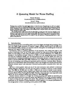
generating function (pgf) A(z). Also, b(n) denotes the the probability that the service time of a packet takes n slots with the corresponding pgf B(z). Now, b(n) depends on the number of nodes contending for the channel as well as the packet length distribution and we now characterize its distribution. The service time of a packet can be broken into two components: (1) the time till the node successfully accesses and reserves the channel for use and (2) the time required to transmit the packet (determined by the packet length distribution). To characterize the £rst component, we refer to Fig. 1. Between any two successful transmissions by a tagged node, other nodes may successfully transmit a number of packets or may be involved in a number of collision, each of which add to the channel access time of the tagged node. We £rst characterize the number of backoff slots that the tagged node has to wait between two successful transmissions. When a packet comes in and £nds that the system is empty it is transmitted without going into backoff, and thus the probability that the number of backoff slots, BO, is zero is given by P [BO = 0] = (1 − ρ)(1 − p). Now with probability ρ the packet goes into backoff at least once. Now, note that if the tagged node successfully transmits the packet in its £rst attempt (with probability 1 − p) the number of backoff slots is uniformly distributed between 1, · · · , CWmin . In case of a successful transmission after a single collision (with probability p(1−p)), the pmf of the number of backoff slots is obtained through U1,CWmin ∗ U1,2CWmin where Ua,b denotes a uniform distribution between a and b and ∗ represents the convolution operation. Following the same procedure for a sequence of successive collisions for the same packet, the probability the tagged node experiences i backoff slots, i > 0, is given by · P [BO = i] = ρ (1 − p)U1,CWmin (i) + p(1 − p) i h U1,CWmin ∗ U1,2CWmin (i) + · · · + pm (1 − p) i h U1,CWmin ∗ U1,2CWmin ∗ · · · ∗ U1,2m CWmin (i) h +pm+1 (1 − p) U1,CWmin ∗ · · · ∗ U1,2m CWmin ∗ ¸ i (11) U1,2m CWmin (i) + · · · with the corresponding pgf BO(z). Note that the maximum number of retransmission attempts allowed for each packet is governed by the long retry count (SLRC) (short retry count (SSRC) for transmissions without the RTS-CTS exchange) which forms the limit on the summation above. However, its effect may be neglected since the term pk (1 − p) becomes negligibly small as k increases. Since the average window size is W (Equation (5)) and a queue is active with probability ρ, the probability that a node attempts a transmission in an arbitrary slot is given by ρ/W . Then, the probability that a given slot is active, q, is given by µ ¶N ρ q =1− 1− (12) W
Then, given that the tagged node experiences i backoff slots before it successfully transmits a packet, the pmf of the number of active slots within the backoff slots is given by µ ¶ i q j (1 − q)i−j (13) P [j slots active|BO = i] = j for j = 0, · · · , i. Unconditioning on i, we have ¶ ∞ µ X i P [j slots active] = q j (1 − q)i−j P [BO = i] (14) j i=j
Also, the probability that a slot results in a collision given that it is active, qc , is given by ´N ³ ´N −1 ³ ρ ρ 1 − − ρN 1− 1− W W W (15) qc = ³ ´N ρ 1− 1− W and thus the probability that out of j active slots k result in collisions is given by µ ¶ j P [k collisions|j active slots] = qck (1 − qc )j−k (16) k Now, each collision adds TC slots to the service time where TC = DIF S + τRT S with τRT S being the time required to transmit a RTS packet. Note that in situations where RTS-CTS packets are not used to reserve the channel, the duration of a collision is given by TC = DIF S + τpkt where τpkt is the packet transmission time. Also, each successful transmission by other nodes between the two successful transmissions of the tagged node adds a time proportional to the packet length of the transmitted packet to the service time at the tagged node. In our analysis we allow for general packet length distributions and the probability that a packet transmission takes n slots (which is dependent on the packet length and the channel rate) is denoted by l(n) with the corresponding pgf L(z). Then, the contribution of j successful transmissions to the service time of the tagged node is given by P[
j X
pkt time = i] = l ∗ l ∗ · · · ∗ l(i) = l(j) (i)
(17)
where l(j) () represents the j−fold convolution of l(n). The contribution of the successful transmissions of the other competing stations and the collisions, X, to service time of the tagged node is then given by µ ¶ j q k (1 − q)j−k · n = kTC + i k P [X = n] = l(j−k) (i)P [SA = k] 0 otherwise (18) where P [SA = k] represents the probability that there are k active slots and is given by Equation (14). The above expression evaluates the probability of the event where there are k slots active between two transmissions from the tagged node, j of which result in collisions contributing kTC slots to the service time while the k − j successful transmissions contribute i slots. Note that the above expression needs to be
Interleaving of transmissions and collisions contributing to the service time.
evaluated for all possible values of i, j and k which result in a given value of n. The pgf of the £nal service time, B(z), which comprises of the backoff slots (BO), the delay due to other stations transmitting (X) and the length of the packet to be served (l) is then given by B(z) = BO(z)X(z)L(z)
(19)
Using standard discrete time queueing theory [1], the pgf of the system occupancy of the G/G/1 queue at random slot boundaries (beginning of a slot), U (z), is given by (z − 1)B(A(z)) U (z) = [1 − A (1)B (1)] z − B(A(z)) 0
Successful transmission by the tagged node
0
(20)
and the pgf of the integer part of the system time (where system time is de£ned as the total time spent in the system from the arrival instant to the service completion time) can be shown to be [1 − A0 (1)B 0 (1)] (z − 1)B(z) [1 − A(B(z))] Vint (z) = A0 (1) [1 − B(z)] [z − A(B(z))] (21) Allowing arrivals to occur at any point in the slot, we denote the distance of the arrival point from the start of the slot by F with mean F . This adds a fractional component to the system time of Vf rac = 1 − F . The total system time is then given by V = Vint + Vf rac whose mean can be expressed as 2
[A0 (1)] B 00 (1) + A00 (1)B 0 (1) V = 1 − F + B (1) + (22) 2 [1 − A0 (1)B 0 (1)] 0
The average queue size at each node can then be obtained using Little’s law and is given by Q = A0 (1)V . Equation (22) can now be solved to obtain the number of nodes that can be supported for arbitrary arrival traf£c patterns while providing a speci£ed delay guarantee. III. S IMULATION R ESULTS To validate our analytic model, we conducted extensive simulations using the simulator ns-2 [6] for different network topologies, number of nodes as well as the load on the network. In this section, we report on our simulation results for the case of 10 and 20 nodes and omit the others since they are similar. The simulations for the results reported in this section were carried out for a rectangular region of 1500 × 500 meters and the nodes were randomly distributed over this region. The routing protocol used for the simulations was Ad-hoc Ondemand Distance Vector routing (AODV) [9] and we also veri£ed our results for routing using Destination Sequenced
Physical Layer Propagation 2 ray gnd Channel Wireless Rx Threshold 3.652e-10 Bandwidth 2 Mbps Frequency 914 MHz Loss Factor 1.0
802.11 RTS size CTS size DIFS SIFS Slot size
MAC 44 bytes 38 bytes 50 µsec 10 µsec 20 µsec
TABLE I S IMULATION S ETTINGS
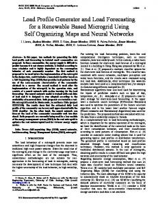
Distance Vector (DSDV) [8]. The interface queues at each mode used a Droptail policy and the interface queue length was set at 50 packets. All sources and receivers have an omni-directional antenna of height 1.5m with transmitter and receiver gains of 1 each. The simulations were run for a simulated time of 1800 seconds. All other parameter settings for the physical and MAC layers for these simulations are given in Table 1. Each node was the source for one ¤ow as well as the sink for another ¤ow. Thus the 10 node case corresponds to 10 ¤ows while the 20 node case had 20 active ¤ows. The arrival process at each node, (a(n)), was assumed to follow the distribution ½ 1−p n=0 (23) a(n) = p n=1 resulting in an average inter-arrival time of 1/p. The sources used UDP as the transport protocol and the packet sizes were assumed to be 1000 bytes. In Figure 2 we compare the simulation results for the collision probabilities with those obtained from our analysis. We also the corresponding analytic results for the collision rates from [12]. We note that our results are a large improvement over existing results and match quite well with the simulations. We also see that while for the 10 node case we have a good match with the simulation results, for the 20 node case we have a little deviation. Figure 3 compares the simulation and analytic results for the average delays for the 10 and 20 node cases along with the results obtained from the analysis of [12]. For both scenarios, we see the close match between the analytic and the simulation results with the analysis of this paper being more closer to the simulations as compared with those of [12]. Also, as expected, the system saturates more quickly for the 20 node cases at approximately half the load of the 10 node case. Similar results were also obtained for other topologies and network sizes, validating the analytic model for the delay in an 802.11 based
0.35
0.45
analysis simulation [12]
0.25 0.20 0.15 0.10 0.05 0.00 0.0
0.5
1.0
1.5
2.0
0.30 0.25 0.20 0.15 0.10
0.00 0.0
2.5
0.5
1.0
1.5
2.0
Average Interarrival Time
Average Interarrival Time
(a) 10 nodes
(b) 20 nodes
2.5
Comparison of the collision probabilities.
0.20
0.20 analysis simulation [12]
0.15
Average Delay (sec)
Average Delay (sec)
0.35
0.05
Fig. 2.
0.10
0.05
0.00 0.0
analysis simulation [12]
0.40
Collision Probability
Collision Probability
0.30
analysis simulation [12]
0.15
0.10
0.05
0.00 0.5
1.0
1.5
2.0
2.5
0.0
0.5
1.0
1.5
Average Interarrival Time
Average Interarrival Time
(a) 10 nodes
(b) 20 nodes
Fig. 3.
2.0
2.5
Comparison of the average packet delays.
network. IV. C ONCLUSIONS In this paper we present an improvement to the queueing model presented in [12] to evaluate the performance of the IEEE 802.11 MAC in terms of its delays and queue lengths and evaluate its capability to support delay sensitive traf£c. The improvement is achieved by explicitly modeling the impact of £nite loas on the loss rates and the queue utilizations. The queueing model for each node in the network accounts for the intricacies of the MAC protocol and its behavior as a function of the number of users in the network. Each node is modeled as a discrete time G/G/1 queue and we allow for arbitrary number of nodes, arrival patterns and packet size distributions. Our analytic results have been veri£ed using extensive simulations and show signi£cant improvements over the results of [12]. R EFERENCES [1] H. Bruneel and B. Kim, Discrete-Time Models for Communication Systems Including ATM, Kluwer Academic Publishers, Boston, 1993. [2] F. Cali, M. Conti and E. Gregori, “IEEE 802.11 protocol: design and performance evaluation of an adaptive backoff mechanism,” IEEE journal on selected areas of Communications, vol. 18, no. 9, pp. 17741786, September 2000. [3] H. Chhaya and S. Gupta, “Performance modeling of asynchronous data transfer methods of IEEE 802.11 MAC protocols,” Wireless Networks, vol. 3, pp. 217-234, 1997.
[4] S. Choi, J. del Prado, S. Nandgopalan and S. Mangold, “IEEE 802.11e contention-based channel access (EDCF) performance evaluation,” Proceedings of IEEE ICC, Anchorage, Ak, May 2003. [5] C. Coutras, S. Gupta and N. Shroff, “Scheduling of real-time traf£c in IEEE 802.11 wireless LANs,” Wireless Networks, vol. 6, no. 6, pp. 457-466, November 2000. [6] K. Fall and K. Varadhan, editors, “ns notes and documentation,” The VINT Project, UC BERKELY, LBL, USC/ISI, and Xerox PARC, November 1997. [7] Wireless LAN Medium Access Control (MAC) and Physical Layer (PHY) Speci£cations, IEEE standards 802.11, January 1997. [8] C. Perkins and P. Bhagwat, “Highly dynamic Destination Sequenced Distance-Vector routing (DSDV) for mobile computers,” Proceedings of ACM SIGCOMM, pp. 234-244, August 1994. [9] C. Perkins and E. Royer. “Ad-hoc On-Demand Distance Vector routing,” Proceedings of IEEE Workshop on Mobile Computing Systems and Applications, pp. 90-100, New Orleans, LA, February 1999. [10] Y. Tay and K. Chua, “A capacity analysis for the IEEE 802.11 MAC protocol,” Wireless Networks, vol. 7, no. 2, pp. 159-171, March, 2001. [11] O. Tickoo and B. Sikdar, “On the impact of IEEE 802.11 MAC on traf£c characteristics,” IEEE Journal on Selected Areas in Communications, vol. 21, no. 2, pp. 189-203, February 2003. [12] O. Tickoo and B. Sikdar, “Queueing analysis and delay mitigation in IEEE 802.11 random access MAC based wireless networks,” Proceedings of IEEE IMFOCOM, Hong Kong, China, March 2004. [13] M. Veeraraghavan, N. Cocker and T. Moors, “Support of voice services in IEEE 802.11 wireless LAN,” Proceedings of IEEE INFOCOM, pp. 488-497, Anchorage, Alaska, April 2001. [14] J. Weinmiller, H. Woesner, J.-P. Ebert and A. Wolisz, “Modi£ed backoff algorithms for DFWMAC’s distributed coordination function,” Proceedings of the 2nd ITG Fachtagung Mobile Kommunikation, pp. 363-370, Neu-Ulm, Germany, September 1995.