2012 9th International Conference on Ubiquitous Intelligence and Computing and 9th International Conference on Autonomic and Trusted Computing
Situation-based Design: a Rapid Approach for Pervasive Application Development Lei Tanga,b, Xingshe Zhoub, Christian Beckerc, Zhiwen Yub, Gregor Schielec a
b
School of Information Engineering, Chang’an University, 710064, P.R.China School of Computer, Northwestern Polytechnical of University, 710072, P.R.China c Information Systems II, University of Mannheim, 68131, Germany
[email protected] x
Abstract—Understanding the user’s requirements and intentions is important when developing pervasive applications. It helps making adaptation decisions and satisfying the user’s needs. In order to do this, the user’s intentions, the current situation and the options for application adaptation have to be taken into account. In this paper we extend prior work on situation modeling and specifying applications with respect to situations. We recapitulate our development language and discuss the development methodology that combines the notion of situation with an application model, thus provides a domain-specific design language and a set of graphical toolkits covering the development lifecycle of a pervasive application. We describe the results from a user study that illustrates the approach and its expressiveness and usability.
specifying a flexible programming structure that takes a form of a negotiation between functional requirements and device capability. x rapid prototyping with a development environment that offers GUI toolkits for design, a language for modeling, and a virtual pervasive environment for testing. The rest of the paper is organized as follows. First, we discuss related work. Next, we investigate the challenges of building pervasive application and derive requirements. Our work is based on a set of concepts, such as pervasive application model and situation modeling technologies. We then detail these features and describe the infrastructure integrating the models as well as the development process based on the infrastructure. We validate how our approach works in practice through a discussion and a brief user study. Finally, we give a conclusion and an outlook.
Keywords-application model; situation model; development methodology; programming toolkits
I. INTRODUCTION
II. RELATED WORK
Mark Weiser published his vision of Ubiquitous Computing more than a decade ago [1]. Meanwhile technological foundations have been developed that allow to realize this vision which is shown by a multitude of research projects. However, this did not happen so far in products, at least not to the anticipated extend. In prior work we analyzed the obstacles to developing ubiquitous computing applications [2]. In a nutshell, we identified the lack of development methodology in general and specifically the gap between design time and runtime as hindering aspects. Different users expect applications to behave different in a given situation. We proposed a design method that allows developers to model the application’s behavior depending on the situation in the physical world and the user’s expectation. User-centered design (UCD) allows to integrate the users’ preference and intentions already at during the early stages of application development. We argue that user requirements on the interactions vary from one situation to another, and also an activity can be observed only when it is carried out in a particular situation. Therefore, thinking of situations as abstractions is an important approach in the application development. To this end, we propose a situation-based design and apply it to the entire design process. This methodology allows a developer to build an application by: x focusing on the human situations evolved into the physical surroundings, rather than the user’s interaction with an interface on a specific device in a specific environment.
978-0-7695-4843-2/12 $26.00 © 2012 IEEE DOI 10.1109/UIC-ATC.2012.58
We discuss related work classified by three dimensions of support for developing pervasive application: methodology, tools and system support. However, system support which focusses on building pervasive application by improving the development of appropriate protocols and techniques is not our concern. Thus we do not discuss related work of this dimension here. A. Methodology support Developing applications is a complex task that has been explored over the past decades in software engineering. However, the dynamics of adaptive applications and the link to user preferences and the physical environment, i.e., the context, make ubiquitous computing applications special. A number of different approaches to engineering ubiquitous computing exist. User Centered Design (UCD) is one promising approach to integrate the user’s intention and preferences into early design stages. Typically designers utilize user studies once (or perhaps twice) during an application’s evolution, e.g. focusing on the early stage for analyzing technical requirement [3]. Later changes in requirements changes are not captured. One exception is the work of Davies et al. [4], which explores the integration of user-driven approach into an e-health application. This work involves a series of three phases to derive the area of interest that can be improved through an iterative technical development, along with a number of prototypes for testing. Due to the time-consuming nature and prohibitively expense introduced by the in-situ evaluation, efforts have been made to discuss how to meet the need of 128
Requirement 2: Ease context usage Pervasive applications are context-aware. Depending on context changes, the application’s behavior will change. Given the number of possible context this can result in complex application architectures. Context processing can happen on different levels from raw sensor data to reasoning processes. We will base our design methodology on the notion of situation which will be used to represent a situation in the physical world. Mapping of situations to context at runtime will decouple the specification of applications and their context aware behavior from the concrete runtime representation. Requirement 3: Dynamic Composition and Adaptation Distributed logic – as in requirement 1 – results in applications that span different devices that are connected by different network technologies. Due to mobility fluctuationsˈ devices become available and unavailable. Thus, the functionality on these devices can also fluctuate. Hence, applications have to react to these fluctuations by adaptation, e.g., selecting alternative components. Requirement 4: Integration of Testing and Deployment Testing pervasive applications is a complex task. A test has to incorporate the variety of the real-world deployment including the user and his intentions and actions [11]. Simulation environments can help users to test applications and build realistic mock-ups of the physical world. It is important that the deployment in the physical world as well as in the simulation environment do not differ. Suitable middleware abstractions that exist in the productive environment as well as in the simulation environment can help to provide uniform deployment processes that work in both environments.
pervasive application testing. Abowd et al. [5] extended the concept of UCD in the design of a mobile and ubiquitous computing application. In their Personal Audio Loop diary study, the designers use the diaries as an experience prototype, to record the reflections of participants in a simulated interaction which makes it clear in understanding the specific design issues (e.g., “how, when, and where people would use the application”.), and identifying the appropriate interruption of the activity flow. However, similar to the work from [6], user studies conducted currently give only a set of qualitative data by observing or interviewing the users. Thus, we argue that a tool which supports the integration of user and task analysis into the design stage is desirable, in order to help identify the design considerations. Additionally, a development environment that supports the UCD methodology is also required for building an application. B. Tool support A number of tools have been developed in the past. Many of them centered around prototyping efforts. The iCAP project [7] allows the end-users to configure the context-aware applications in their instrumented environments. It encapsulates the user-defined entities as separate builders and enables constructing a rule form rapidly. An approach that involves the end users in the deployment process is FedNet [8] that exposes the contextual changes as the functionalities of some instrumented artifacts, and enables the applications to be developed in a user-centric way around these context changes. Another example with underlying notion of UCD is ActivityDesigner [9] that models the activity context as several independent scenes and allows the developer to create stream-based application behavior by customizing transitions using different scenes. Testing in a simulated environment allows the designers to objectively assess the prototypes. One toolkit that simulates the physical environment surrounding wireless devices and the users for pervasive applications is described in UbiWise [10]. When testing with UbiWise, all events are encapsulated as messages that are communicated between the environment and devices allowing to simulate the devices’ behaviors. Previous work has made different efforts to address application development. We advocate a novel methodology based on a user-centric application model. Linking the application model to situations allows the designer to model the application according to user’s preferences and expectations.
IV. SITUATION-BASED DESIGN METHODOLOGY In accordance with the requirements discussed before, we present a situation-based design approach (SBD) to help the developers realize a pervasive application through a step-by-step process. Situation, “a description of the states of relevant entities” [12], can be thought as a higher level of abstraction related to the user’s intention. We will use situations as a core abstraction for modeling and programming pervasive applications. A. User-Centric Application Model An application model should support the aforementioned requirements. In essence this means, that dynamic composition must be supported as well as adaptation, i.e., the change of composition over time. Adaptation needs to refer to context including the user’s intentions in order to find a configuration that meets the user preferences in a given situation. In order to support adaptation a pervasive application has to take into account the user’s intention and include this into the mapping of the application’s tasks. In order to accomplish this, an application model has to provide means to capture the user’s intentions as well as the functional requirements to map the application’s functionality to the available resources.
III. REQUIREMENT OF DEVELOPING PERVASIVE APPLICATION
We will discuss four requirements that should be fulfilled by a development methodology for Pervasive Application. Requirement 1: Support of distributed logic Devices in Pervasive Computing are often specialized or mobile. As a result they have to cooperate in order to realize complex functionality. Thus an appropriate middleware is needed to discover and utilize functionality.
129
e.g., if other applications for the same user or a group with similar preferences are modeled. We define the situation as a set of user tasks performed under certain circumstances as shown in Figure 2, where a task will be performed by a set of interactions between the user and objects (devices). In other words, it needs a set of user actions and interactive object actions for accomplishing the task goal. For example, there is “presentation task” involved in the meeting situation where “user presents” (user action) and “projector opens” (object action) will be performed. Due to the need for the descriptions of context-awareness, the term of “Action” is modeled as a definition of its preconditions and effects related to the contexts. Our model of situation differs from others [13] in that the definition aims at demonstrating how a human perceives the world and himself. With our model, the situation can capture the user-specific information that is usually described as “what happens to who” and “when, where and why it happens” in natural language. In addition, the model also gives a way to define how the user task is done. Therefore, it is possible to extract the functions required rapidly, as well as to make the end-user understand the design better by showing the information to them.
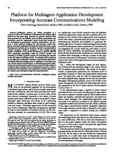
We present a novel application model bridging the gap between design time and an application’s run-time. It requires a user-centric description which captures the purpose of the user interaction at a high level, specifying the application in terms of its requirements as well as the required functionality of devices based on their capabilities. Figure 1 depicts the general application model meets the aforementioned requirements. It allows the developers to specify the user’s intentions with the task description, specify the instantiation of services on devices in an abstract manner, so that it enables the available services required by the tasks to be discovered in the environment and be implemented with the suitable device capability. The application model is composed of four elements. The task-based model describes the abstract user interactions, including the goal, the “flow" through the tasks, and the necessary information that the user needs to perform the task. The “task-service” models the expected functions for each (sub) tasks. In addition, the service-based model specifies the expected devices’ capability with the “service-device”. By linking it with the “environment-based” model, the application is structured in order to become context-aware. Specifically, the “service precondition” and “service effect” model the fact that once the context changes, the application’s behavior changes, and vice versa. Furthermore, the “context change” allows the developer to define the changes happening in the physical environment. The device-based model abstracts from the differences in the device with “device-service”, and “device-interaction”. As shown in Figure 1, the four elements involving the application run-time can be modeled in a pervasive design language (PerDL) presented in our early work. With the application model, the development will be directed at the level of specifying the abstract functions and connecting it with the available device capability, which thus meets the requirements 1 and 3.
situation
task user action
precondition
Service-Task Service-Device Service Precondition Service Effect
Environment-based model Context Type Context Change
task
task
user action
effect
ĂĂ
situation
contextual requirement
object action
situation
contextual requirement
object action
precondition
effect
Figure 2. Graphical representation of situation model, where the arrow indicates “is made of”.
C. Application Development with situation model The situation based design (SBD) process aims to provide a systematic methodology and adequate tool support that realizes the generation of application code. Figure 3 illustrates the framework of SBD which covers the phases of application development, including the application analysis, function design and implementation. Initially the contextual knowledge is identified and structured as the situation model. Then the templates related to user action, task and situation are derived from the model. In the second phase, a set of the functional and conditional components are identified within the available templates, defining where the template is used to initiate changes on application logics, which enables the application to behave context-aware. As a result, a platform-independent application model is generated. In the application implementation phase, the transformation accepts a model which is described in PerDL as input and generates an output model in JAVA. The final phase is model-to-code generation, where the implementation is generated via a code generator in the form of templates. The application code can be deployed and executed in a testing environment.
Task-based model
Service-based model
situation
Task goal Task-Service Task Precondition Task info
Device-based model Device-Service Device-Interaction UI Properties
Figure 1. Illustration of partial application model that structures an application with four interdependent parts: task, service, device and environment.
B. Situation Model There are many ways to describe a situation, ranging from ontologies, first-order logic theories, to logic programming language. In our approach, the notion of situation is presented as a way to encapsulate the underlying contexts as the user-specific knowledge being applied in the development. Thus it should expose the critical information of a user to the developer, e.g., what the user is paying attention to, what is important to the user. Furthermore, such knowledge should be shared, combined and allow for reuse,
130
Application Implementation
Code Template
input
for the transition (Figure 5(a)). Thus, if the effect (i.e. “Position is changed”) introduced by the template is detected at runtime, it will then execute the “Show” component.
Application Code generate Code Generator
Application Analysis
input
input
customize OWL Editor
define
Situation Model
Situation-based Templates
extract
Target Model
input Context Editor Logic Editor
generate define
PerDL Model
input
Transform
Function Design
(a)
Figure 3. Framework of the SBD
V. EXAMPLE APPLICATION One can imagine a location-aware visual experience where the developer can realize an application under a common situation setting: a lab tour for visitors. The scenario can be described as follows: After the meeting, Peter, the chairman, welcomes the attendees to visit his laboratory which integrates various pervasive devices. The visitors wander through the space, look at the information shown on the nearest displays, and hear the introductions about each techniques used through the owners’ voices. The devices automatically detect visitors and react accordingly.
(b)
A. How it works The developer first creates the templates involved in the scenario and adds them to the repository. There are three types of actions (i.e., “walking”, “sensing” and “playing”), two kinds of tasks (i.e., “view” and “listen”) and one core situation (i.e., “visit a lab”). For each action, the developer drags the “user action” icon onto the template sheets and creates a new action. Either by picking up an existing one or customizing a new one with the editor (Figure 4(a)). He then specifies the precondition and effect of the action with the contextual alternatives which are extracted from the situation model. The next step is to build the user task. The developer connects the task and action icons to define which actions are needed to perform the task as well as to specify the way in which the actions should be undertaken (Figure 4(b)). The final step is to build the situation instance. The developer selects the desired icons from the list provided, and decides the place and time where the situation can happen and should be handled by the application (Figure 4(c)). In addition, the user can build another situation, “visiting a campus” for example, or something where the same task should be performed, only by changing the contextual requirements. This allows to reuse already modeled actions in other situations easily. The designed application is now ready for designing the application semantics by simply selecting the appropriate templates as the transitions happening between different functions. To specify these functions, the developer structures it as a set of components, in our case “Detect” and “Show”, and uses the “walking” template as the condition
(c) Figure 4. (a) Creation of the “playing” action. (b) Creation of the “view” task. (c) Creation of the “visit a lab” situation
In order to realize the interactions between the services and map these to devices, the object’s actions are modeled as abstract device capabilities. Then, the developer connects the functions and device capabilities in order to specify what kind of devices each component needs. For an example (executing the service “DisplayService”) see Figure 5(b). Next, the developer implements a prototype in JAVA using the code generation process. The input model defines the structure of services described in PerDL. It abstracts from the underlying function and device capability by introducing means by which the user performs the task.
131
class Detect extends Component{ interface send_event="REQUEST= TOSTART"; } class Location extends Context{ interface event = “LOCATION.changed”; void getCurrentValue();} ……
To deploy the prototype for rapid testing, the developer selects the output model and creates a tree-based mapping. He then defines the key components used in the testing environment, including the name and corresponding message (Figure 6). In this case, the developer identifies an instance of “Detect” by defining what kind of sensor data the component can detect, and an instance of “Show” by defining which action command the component needs to execute. As a result, a new tree-based model is generated. (a)
Figure 6. Implementation of prototype deployed into the testing environment. (b)
Finally, the developer can test the application by constructing a visit scenario. The developer first selects a monitor as the virtual actuator and an RFID as a sensor from the “virtual device” library. By dragging them into the constructor plane and configuring them, e.g., defining the sense capability of the RFID sensor with the templates in the Linden Scripting Language (LSL), the developer can either control the avatar’s movement or the context inputs, to see if the application behaves as expected. Figure 7(a) shows the environment configuration, where two groups (a sensor and an actuator) are placed to be far away from each other in order to simulate different rooms. By moving the avatar close to a group the correct handling of events can be tested, as shown in Figure 7(b), where the virtual actuator will be active to change its color accordingly to the approaching/leaving user (Figure 7(c)).
Figure 5. Logic layout for the example application: the device will start a show when user is near to it
The output prototype includes the implementation specific details which conform to the operational semantics of JAVA. It consists of class definitions, class instances and the control flows. There are two kinds of classes, i.e., “component” and “context”, as well as two kinds of events. The “send_event” is responsible for the communication between the components and devices, while the “receive_event” received from the “EventListener” function is used for the specification of flows between different components. The main part of prototype is shown below: public Display(){//class instance LOCATION context1=new LOCATION(); REQUEST context2=new REQUEST(); STATE context3=new STATE(); Detect comp1=new Detect(); Show comp2=new Show(); //flows comp1.SentEvent(comp1.sent_event); while(true){ comp2.EventListener(e); if(e.equals(context1.event)) break;} comp2.SentEvent(comp2.sent_event); comp2.ContextChange(STATE,= ,OPEN){ context3.refreshValue();} }…… //class definition
(a)
132
(b)
guide for representing the structure of an application and creating rapid functional prototyping but is also complemented by tools. A Model View Controller-based (MVC) approach organizes the input, output and internal realization of our editor. Figure 9 depicts the interaction within the MVC framework when an application is modeled. The view component first receives the requests from the interactions between the developer and the system, e.g., to build a new graphical component, and actives the corresponding controller. 1) PerEditor Interaction With the graphical user interface, the PerEditor allows the functional prototypes to be set up rapidly, without writing any codes. There are two steps for the Interactions with the PerEditor. a) Creating the situation-based templates The system provides reusable templates as the mediator between the user-specified situation model and the step-by-step development methodology. The developer can simply drag the required icons from the tool panel onto the PerEditor, and define the corresponding properties. The precondition and effect of each action will be defined as a description relevant to the contexts which are extracted from the situation model. Since such descriptions are separated as three parts (i.e. “Type”, “Operator” and “Instance”), the effect is represented as, e.g., “It is very likely that the “State” context is “EQUAL” “OPEN” is happening”. All the situation-based templates can be added to the repository automatically.
(c) Figure 7. Simulation testing
VI. THE PERDE SYSTEM This chapter presents the design of PerDE system which realizes the development environment of the situation-based design approach. A. Architecture The architecture of the PerDE system is structured as shown in Figure 8. The basic strategie of PerDE is to design an application with PerDL using the graphical toolkits, and to complement it with separated functional components that can be deployed into the testing environment. The design in the development framework of the situation based design process SBD starts with the PerEditor which acts as the ContextEditor and the LogicEditor shown in Figure 3. The ModelCreator which implements the OWLEditor shown in Figure 3 is responsible for building the situation model, while the Converter is used in the phase of the application implementation. Based on this component-based prototype, a mapping by using the Code generator to the virtual pervasive environment, that we named PerVE (pronounced Pe-Ve), will support rapid configuration and simulation testing. The simulation environment is realized as a virtual 3D world, where the virtual entities are represented as plug-in modules of the OpenSim server. The BASE [14] middleware provides supports for executing the application, including discovering the available services and accessing the device capabilities by allowing the virtual entities to communicate with the aggregators. The PerDE system also enables a rapid access to all the templates housed in the PerDataBase, e.g., the PerDL description of the application semantics as well as the code templates for the transformation. Component Aggregator
Application
PerEditor
PerDataBase .perdl
.owl
.java
Code generator
Convertor
Controller ĸ Passes calls to
Tool Panel
View
Ļ Updates
C
Ĺ Changes something Or Requests some data
User Interaction
ĺ Fires events Ă
Legend R:Request C: Command V: Variable
V
Model Method getXX() setXX() ĂĂ
Figure 9. MVC-based Framework of the design system
b) Constructing the application semantics In our approach, the application semantics will be described as a composition of different services in conjunction with the situation-based templates. In order to specify the services abstractly, PerEditor provides a way to express the expected functions of a service by using a set of components and conditions as well as to specify the required device capability for instantiating these services. The system provides a default programming structure for the navigation design, where the situation-based templates are organized as a tree-based model which is able to be used as the alternatives of transition conditions involved in the application semantics. 2) Convertor Interaction The system realizes the translation from the PerDL-based model to the actual implementation in JAVA.
ModelCreator
Design Tools
BASE Middleware
Simulation environmet
ķ Action
R
Evaluation System
Figure 8. System architecture
B. The design tools At design-time where the application will be created in a user-specific way, the PerDE process not only serves as the
133
a) Creating a component-based prototype The prototype is created based on a template for the transformation. The template defines the rules to parse the concepts involved in the PerDL-based model, e.g., “subcomponent”, “precondition” and “dependency”. Each component is represented by some code template conforming to the target language, in our case Java. Specifically, a component introduces a set of events and commands that are used to offer the services of a device.
The Communication Service is responsible for the connections to the virtual sensors and actuators as well as communicating with them in order to receive the data and send the commands over HTTP. The Local Management Service realizes subscriptions of an interest in receiving data, stores the data including the IncomingMessages as well as updates to the CapabilitiesRegistry, and distributes it to other services. The Global Management Service enables the subscriptions of the requirements from the application, and forwards them to other services. 1) PerVE: a virtual testing environment In order to allow for simulated testing, PerVE emulates the computing and communication capabilities of a real pervasive computing environment. Furthermore, it implements the context-awareness by allowing the virtual entities to react to the various contexts generated. By replaying context traces, experiments can be repeated and comparison of approaches can be based on the same data/context set. Based on the OpenDynamicsEngine, it is possible to simulate the context input. Figure 11(a) illustrates the implementation of simulating the changes over the light intensity, where a command described in Linden Scripting Language (LSL) is given. Figure 11(b) is an example where the actuator reacts to the command and moves as it could in the real world. With a timer, the distance between the avatar and actuator is detected continuously and sent as the message over HTTP.
C. The evaluation system In order to simulate an application in our evaluation system, the generated entities have to be executed in the simulation environment. Technically this means, that the generated entities have to be linked to the events generated between the entities in this simulation. The code generator constructs so called aggregators that employ the message subscription for receiving the sensor data (from simulated as well as from manually activated sensors) and sending the corresponding action commands to the virtual entities. There are two kinds of messages involved in the resulting implementation. The “outgoing” message is responsible for specifying the acting capability and the “incoming” one is used to specify the type of data detected. At run-time, the developer invokes the application and tests its functionality. Figure 10 illustrates the simplified infrastructure of the system and the way it works. The underlying simulation environment is realized by the OpenSim server as a platform for hosting a virtual world. This virtual world allows the creation and programmability of virtual entities, that provide the sensor functionality or acting capabilities of entities, such as users or devices. The BASE middleware is extended to support the execution of the pervasive applications. 1) it enables the applications to be formed as the services and implements the communication protocols allowing the remote devices to be accessed; 2) it supports the discovery of available services through its own discovery plug-ins, as well as the redistribution of the communication path to reach the new service.
float _Cycle = 0.5; float intensity = 0.2; timer(){ float now = llGetTime(); if ((now - lastCaculate) >= _Cycle){ caculate(); lastCaculate = now; send(ĀOnLightChangedā, Ācaculate()ā); } } default{ state_entry(){ lastCaculate = llGetTime(); llListen(0, "", "", ""); llSetTimerEvent(_Cycle); timer();} } (a)
invocation
BASE
VS: virtual sensor
VA: virtual actuator
Communication Service
Local Management Service
invocation
if (command == "llmovetotarget"){ change = TRUE; llMoveToTarget(llList2Vector(l,1), llList2Integer(l,1));} return change; } (b)
VII. EVALUATION HTTP
VS
We evaluate PerDE in two ways. First, we describe the results of a user study we performed in order to investigate the usability of PerDE based on a health care application. Second, we show how PerDE enables the developer to rapidly build an application based on complexity measurements using the navigation system discussed in Section V.
VS VA
network
BASE Transport Plug-ins
Global Management Service
Transport Plug-ins
interface
network
M:outgoing M:incoming
Communication Service
A
A
Local Management Service
Transport Plug-ins
A
integer change = FALSE; string command = llStringTrim (llToLower(llList2String(l,0)), 1);
Figure 11. (a) it simulates a input of the light intensity. (b) A movement is simulated when the actuator reacts to a command.
BASE
Application
integer executeAction(list l){
HTTP
A: aggregator
Simulation Environment
VS
VS
A. User Study To better understand the usability of the PerDE, we had ten experienced programmers to use the system and give us their feedbacks. Most users were slightly familiar with the notion of situation, but none had ever built an application with a situation based or similar approach. They were asked to build a (simple) smart healthcare application where a
M: message
Figure 10. Infrastructure of the system, where VA,VS, A and M denote virtual actuator, virtual sensor, aggregator and message respectively.
We developed three additional services to structure the communications between the devices and the applications.
134
proactive reminder is delivered when a defined situation occurs, i.e., a medication has to be taken.
time lies in ca. 24 ms for the XML RPC and 23 ms for the HTTP based communication. For most interactions in distributed Pervasive Computing applications this is a tolerable overhead.
TABLE І. AVERAGE SCORE. 5=ACCREDIT STRONGLY; 4=ACCREDIT; 3=NEUTRAL; 2=DENY; 1=DENY STRONGLY Questions I’m interested in the SBD No need to care about the underlying data I’m satisfied with rapid development
Score 3.8 5.0 4.8
Evaluation system
It is useful to simulation testing
4.0
All
It is easy to use the PerDE I will use it again
4.6 4.8
Design system
VII. CONCLUSION In this paper we extended prior work for our situation-based design method. The design method provides means to model the application structure and allows the developer to leverage the notion of situation as a way to describe the application semantics. PerDE, a novel development environment, realizes the method and supports the whole process with graphical toolkits. A code generator transforms the models from design time into code. In order to provide means for testing and debugging, an application can be deployed into a simulation environment, where interaction with sensors and actuators can be simulated and traces allow to compare different prototypes, e.g., configuration strategies. In future work we are going to provide more evidences to show the usability of PerDE, and we want to integrate the suggestions from our user study and work on a broader set of templates for situations along with applying situation based design to more complex applications.
Table І shows the averaged scores of a small questionnaire after completing the development. The user study shows that the approach is effective and conforms that PerDE is a usable system. Beyond this success, there were two noticeable cases in the user studies. First, it took quite a long time to introduce the idea of SBD to the users. Most users had no idea of user centric design before. Thus, they had no experience in analyzing users and their tasks. Users showed an improved performance in completing the second template. They requested changes in PerVE, e.g., a functionality to configure context in the physical world. B. Performance analysis To validate the supports in rapid development, a CCCC tool is introduced to analyze the performance in the reduction of time and efforts on the development. Two metrics, i.e., the lines of code (LOC) and Cyclomatic complexity (CycloC) are used to conduct the testing on different implementations of the context-aware navigation application from Section V in JAVA and J2ME. TableII shows the results where 84.9% and 73% codes can be generated automatically, according to the evaluation with LOC. Furthermore, the results of a comparison of the CycloC illustrate that the prototype carries a low complexity. However, this can mainly attributed to the fact that the generated code is rather simple.
REFERENCES [1] M. Weiser (1991). The computer for the 21st century. Scientific American 265(3): 94-104. [2] L. Tang, Z. Yu, X. Zhou, G. Schiele, C. Becker (2010) PerDE: Towards a Rapid Design and Evaluation Environment for Pervasive Application. ICPS 2010, ACM:186-191 [3] S. Consolvo, L. Arnstein,B. Franza (2002). User study techniques in the design and evaluation of a ubicomp environment. UbiComp 2002: 73-90. [4] R. Davies, C. Nugent, M. Donnelly, et al. (2009). A user driven approach to develop a cognitive prosthetic to address the unmet needs of people with mild dementia. Pervasive and Mobile Computing 5(3): 253-267. [5] G. D. Abowd, G. R. Hayes, G. Iachello, et al. (2005). Prototypes and paratypes: Designing mobile and ubiquitous computing applications. Pervasive Computing, IEEE 4(4): 67-73. [6] D. Fitton, K. Cheverst, C. Kray, et al. (2005). Rapid prototyping and user-centered design of interactive display-based systems. Pervasive Computing, IEEE 4(4): 58-66. [7] T. Sohn, A. Dey (2003). iCAP: an informal tool for interactive prototyping of context-aware applications. CHI Extended Abstracts 2003, ACM: 974-975. [8] F. Kawsar, T. Nakajima,K. Fujinami (2008). Deploy spontaneously: supporting end-users in building and enhancing a smart home. UbiComp 2008, ACM: 282-291. [9] Y. Li, J. A. Landay (2008). Activity-based prototyping of ubicomp applications for long-lived, everyday human activities. CHI 2008, ACM: 1303-1312. [10] J. Barton, J.,V. Vijayaraghavan (2002). UBIWISE, a simulator for ubiquitous computing systems design, Technical Report, HPL-2003-93. [11] L. Tang, Z. Yu, X. Zhou, H. Wang, C. Becker (2011). Supporting rapid design and evaluation of pervasive applications: challenges and solutions. Personal and ubiquitous computing 15(3): 253-269. [12] A. K. Dey. (2001). Understanding and using context. Personal and ubiquitous computing 5(1): 4-7. [13] P. Bruegger, D. Lalanne, A. Lisowska, et al. (2009). Tools for designing and prototyping activity-based pervasive applications. MoMM 2009, ACM: 129-136. [14] C. Becker, G. Schiele, H. Gubbels, et al. (2003). Base - a micro-broker-based middleware for pervasive computing. PerCom 2003: 443-451.
TABLE II. EFFECTIVENESS OF THE PERDE SYSTEM Metrics
Code generated automatically Overall
J A V A J 2 M E
LOC CycloC Number
4096 45
All code
Per module
Overall
146.285 1.607
4820 61
Per module
155.484 1.968
Module Number
28
/
31
/
LOC CycloC Number
4683 117
114.220 2.857
6413 148
128.260 2.960
Module Number
41
/
50
/
The PerDE provides two kinds of communication modes, i.e., XML-RPCs and HTTP, for enabling the applications to be executed in the simulator. It is crucial that the interaction between application components and the simulation environment is not delayed to allow proper tests. Two experiments were conducted by running the application with two modes respectively, and the results were calculated from 100 samples. The average response
135