that captures the device infrastructure, business opera- tion structure, and their relationship. Building on the model, a management system can be designed to ...
A Model-Driven Approach to RFID Application Programming and Infrastructure Management Han Chen, Paul B. Chou, Sastry Duri, Jeffery G. Elliott, Johnathan M. Reason, Danny C. Wong IBM T.J. Watson Research Center {chenhan, pchou, sastry, jge, reason, dcwong}@us.ibm.com Abstract This paper describes a model-driven methodology to provide a systematic means of programming RFID applications and managing a distributed RFID infrastructure. The centerpiece of the approach is a model that captures the device infrastructure, business operation structure, and their relationship. Building on the model, a management system can be designed to support various management tasks effectively, such as the enrollment, provisioning, and monitoring of devices. Similarly an application framework can be created for solution developers to create distributed RFID applications. Applications can be written against a business operation model and deployed on an evolving device infrastructure. A prototype shows that the approach facilitates the management and programming of an RFID infrastructure.
1. Introduction Radio Frequency Identification (RFID) technology has existed for over thirty years [4] and has found many applications such as proximity access badge, automatic highway toll collection, gasoline station payment device, etc. The prospect of producing RFID tags at extremely low cost has attracted the attention of businesses in recent years. A so-called passive tag consists of a tiny silicon chip attached to an antenna printed on a plastic substrate. The antenna converts radiation emitted from a reader into electrical energy and powers up the circuitry. The incoming signal is then modulated with the tag id and sent back to the reader. Compared with its close relative, the omnipresent barcode, passive RFID technology has many advantages. First, there is no line-of-sight requirement for reading a tag, which allows tagged objects to be randomly oriented. Second, access algorithms are built-in to the reader protocol to allow multiple tags to be read simultaneously, which greatly improves the read speed. Third, RFID tags can potentially carry a large number of bits, which allows rich information to be stored with an item. Fourth, RFID tags can be made writable, which enables appli-
cations that are not possible with barcodes, e.g., product movement history. These properties promise to provide businesses benefits including improved operational productivity and efficiency. Industry leaders and government agencies across the world have put forth aggressive mandates in areas such as supply chain management, product traceability, and manufacturing production [1][2]. The most visible result of these mandates is the numerous pilot projects being conducted by major retailers and the suppliers. Thus far, the majority of these pilots have focused on the basic functional operation of RFID technology; namely, reading tag data, filtering tag data, communicating tag data up-stream to business applications, and validating tag data. Meanwhile, to help address some of the RFID device interoperability problems, there are various efforts in standardizing low-level communication protocols. For example, EPCglobal Inc™ has efforts to define supply-chain standards for RFID reader management, filtering and collection of RFID tags, and inter-company Electronic Product Code (EPC) information sharing [3]. While these efforts are very valuable, they are only part of the end-to-end story for an RFID deployment. To derive real value from RFID technology, businesses need to fully integrate their RFID infrastructure into existing information and business infrastructures. An RFID infrastructure should be programmable to support specific business objectives and manageable as part of a business’ information technology (IT) network. Unfortunately, to our knowledge, none of the existing pilot deployments are capable of addressing the areas of programmability and manageability. This paper describes a model-driven methodology that provides a systematic means to manage and program an RFID infrastructure. At the core of our methodology is a model that captures the RFID IT infrastructure, business operation structure, and the relationship between them. Using this model, we describe a management system that supports common management tasks, such as the enrollment, provisioning, and monitoring of RFID devices. We also describe an application framework that solution developers can use to
Proceedings of the 2005 IEEE International Conference on e-Business Engineering (ICEBE’05) 0-7695-2430-3/05 $20.00 © 2005
IEEE
1. ASN
Device Controller
Processing Unit
Processing Unit
integration
Processing Unit
Shipper
Back-end System
ime 2. T
Carrier
Receiver
n atio loc and
5. Match 6. Shortage
3. EPCs RFID Reader
4. Tags
Dock door controller
Light Stack
7. Unexpected
Device Controller RFID Reader
Light Stack
Figure 2. Goods receipt verification process Motion Sensor
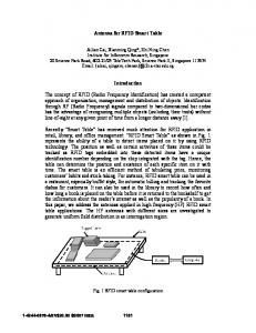
Figure 1. An RFID infrastructure
create distributed RFID applications. Applications can be written against a business operation model and deployed on an evolving device infrastructure. Using a prototype implementation, we describe how our approach facilitates managing and programming an RFID infrastructure. The rest of the paper is organized as follows. Section 2 describes some common use cases and requirements we learn from working with customers. Section 3 describes a model-driven approach to the problems of programming and managing an RFID infrastructure. Section 4 summarizes this paper.
2. Experiences and Lessons Learned In 2004, several large retailers around the world have started small scale pilot RFID projects with a plan for progressively rolling out a full scale deployment in the near future. Most of the pilots are in the supply chain management area, in which RFID enabled dock doors are used to track the movement of goods. A typical pilot project involves a few distribution centers and stores. A number of dock doors are chosen to be RFID-enabled. For each dock door, one or more RFID readers with multiple antennas are used. The antennas are mounted on a stand around the dock door space and are oriented to provide good read coverage. A computing device is used as the controller for the reader. It communicates with enterprise systems to send and receive business objects. Usually, an embedded platform is favored for its compactness, low power consumption, and low maintenance. The deployment might be augmented with various sensor modalities. For example, light stacks with multiple colors and buzzers are used to indicate the current operational status; motion sensors are used to detect incoming goods and turn on the reader automatically. These sensors and actuators are typically connected to the device controller. As a cost saving measure, a single device controller may be used for more than one dock door. In an enterprise-wide deployment of RFID technology, there might be tens of thousands readers and other sensors and actuators along with associated device controllers. They all need to be integrated to the exist-
ing enterprise computing infrastructure. For better scalability, intermediate processing units (PU) can be employed to provide necessary mediation including event filtering, aggregation, persistence, and routing. Each PU is a computing device, typically on a server platform, connected to multiple device controllers or other down-stream PU’s. A PU can be deployed at the enterprise level, geographic division level, and/or store level to achieve the desired scalability. Business integration with back-end systems can happen at each level depending on the operation model. This hierarchy of computing devices and sensors and actuators forms an RFID infrastructure (Figure 1). A common use case related to RFID-enabled dock doors is the Goods Receipt Verification process, as outlined below and in Figure 2. 1. The shipper sends the receiver an augmented Advanced Shipping Notice (ASN), which contains a list of EPC tag numbers of the goods in the shipment. 2. The receiver schedules the time and dock door location for the shipment to arrive with the carrier. 3. The receiver sends the ASN with the list of EPC codes to the target receiving dock door. 4. When the goods arrive, they are unloaded and moved through the dock door. RFID tags affixed to the cases and pallets are read and compared against the expected list of tags stored in the controller. 5. After scanning finishes, if all expected tags are read correctly, the controller reports to the enterprise system indicating success and a green light is lit. 6. If not all expected tags are read, the controller reports shortage and a yellow light is lit. 7. At any time during the scanning, if an unexpected tag is encountered, the controller immediately turns on a red light to alert the operator so that the erroneous goods can be reloaded back to the truck. There are variants of this process, for example, the tag comparison may happen in the back-end system instead of at the controller. Other use cases include perpetual inventory using smart shelves, print-tag-andship process, etc. A robust programming framework should support all these use cases. We have identified the following functional requirements for it to do so. 1. A communication mechanism for sending messages representing business objects, e.g., ASN’s, from an enterprise system to PU’s or device controllers.
Proceedings of the 2005 IEEE International Conference on e-Business Engineering (ICEBE’05) 0-7695-2430-3/05 $20.00 © 2005
IEEE
2. A communication mechanism for controllers and PU’s to report upstream to a business integration point. 3. A mechanism to distribute application logic to PU’s and device controllers. For example, an inventory application may need to aggregate partial reports from smart shelf controllers at intermediate levels. One key lesson learned in developing applications for RFID pilot projects leads to an important nonfunctional requirement, i.e., the application programming framework should decouple the business logic from the underlying RFID infrastructure. As an RFID deployment is gradually rolled out, the infrastructure will evolve. The application programming framework should make sure that this evolution does not affect business logic, so that an existing deployment can continue to function without intervention. An application programming framework makes the RFID infrastructure useful. To be utterly usable, it also needs good management support. Otherwise, the cost overhead associated with operating the infrastructure could potentially offset any benefits the RFID technology is able to bring to a business. The following is a list of common management functional requirements: 1. Device enrollment. When a new device (controller or sensor and actuator) is deployed, it needs to “join” the existing RFID infrastructure. 2. Device provisioning and configuration. Software is downloaded to the device, installed and configured. 3. Device replacement/upgrade. When a device is damaged or can no longer meet the requirement, it is removed and a replacement device is installed. This may trigger the enrollment and provisioning processes. 4. Device movement. An existing device may be repurposed, for example, moving a device controller from dock door #1 to #2. 5. Device status monitoring. In order for IT administration staff to remotely monitor the operation of the RFID infrastructure, devices should be able to report their operational status dynamically. 6. Device configuration update. During pilot deployments, we observe that, unlike traditional IT, an RFID infrastructure contains a large amount of assets deployed in the operation field that is often environmentally rugged and usually does not have support from an on-site IT staff. This leads to two non-functional management requirements: 1. Most, if not all, management tasks should be simple enough to be carried out by personnel with very little technology knowledge or training. 2. It should be feasible to remotely perform any task that must involve experienced IT staff. In the next section we propose a model-driven approach that satisfies these requirements for programming and managing a large-scale RFID deployment.
3. A Model-Driven Methodology To ease the programming of distributed RFID applications and management of the infrastructure, we adopt a model-driven methodology. The core idea is to capture the information about the entire infrastructure in an accurate model, which supports the programming framework and the management applications. Figure 3 shows a high-level view of this approach. We first create a meta-model for the domain of RFID infrastructure programming and management. A modeling tool is used to create an instance model for a specific deployment based on requirements. Instance objects of the model, such as processing nodes, controllers, readers, and lights, are created and stored in a hosting engine, such as a directory service. The application framework runs on the processing nodes and device controllers. It acts as a client to the hosting engine to provide model-related services to the applications, such as dynamic message routing based on infrastructure topology. Relevant portions of the model are replicated and cached in the application framework to enhance performance and scalability. The management applications also act as clients to the model. Management processes are designed such that any physical operations on the infrastructure are reflected as changes to the model, thus keeping the model in sync with the infrastructure. Due to space limit, we focus on the modeling processing itself, without going into details about the programming framework and management applications. Many of the difficulties we encountered in previous efforts of programming an RFID infrastructure result from the inter-mingling of business concepts and IT concepts. Consider a controller with IP address 1.2.3.4 that is used for a receiving dock door at store #2000 of company MegaMart. The business concepts—dock door, store, and company—are relatively static unless there is a change in the way the business is organized. However, the IP address as an IT concept is more dyRFID infrastructure Deployment Requirement
Query Interface Modeler Meta-model
IEEE
Management Applications Update Interface
Hosting Engine infrastructure model
Figure 3. A model-driven methodology of programming and managing RFID infrastructure
Proceedings of the 2005 IEEE International Conference on e-Business Engineering (ICEBE’05) 0-7695-2430-3/05 $20.00 © 2005
Application Framework
Business Concepts
IT Concepts
Business Hierarchy
IT Hierarchy
Device Instances
MegaMart
Processing Unit
Store #2000
Processing Unit
Hierarchy
Attribute
Relationship
Object
Container
Item
Controller #1
Containment Receiving Dept.
Device Controller
Device Controller
RFID Reader
RFID Reader
Controller #2
Dock Door #1
Dock Door #2
Figure 4. A three-tier RFID infrastructure model
namic. When an RFID infrastructure is gradually rolled out, the deployment structure and thus the associations between IT and business concepts will inevitably change over time. If we allow applications to be written using business concepts instead of IT concepts, they are much more likely to survive the evolution of the infrastructure. Therefore, we introduce a business hierarchy and an IT hierarchy in our model. The business hierarchy captures the containment relationship among business entities. For example, a model of business hierarchy may include four levels: company, store location, department, and functional unit. The aforementioned dock door is represented as a tuple (MegaMart, Store #2000, Receiving Department, Dock door #1). The IT hierarchy is used to model the containment relationship among sensors and actuators, device controllers, and processing units in the infrastructure. The framework translates business concepts into IT ones through a construct called Mapping, which links an entity in one hierarchy to another entity in different hierarchy. In this example, we map an IT entity to a business entity, with the constraint that the mapping target of a contained entity is contained by the mapping target of the containing entity. By separating the IT hierarchy from the business hierarchy, we achieve our goal of shielding the evolving infrastructure from applications. However, a single IT hierarchy is not sufficient to model many management operations. A device in the IT hierarchy has two distinct sets of attributes. One set of attributes is inherent to the device itself, for example, serial number, MAC address, etc. The other set is only acquired when the device is deployed, for example, its IP address, its parent processing node in the hierarchy, etc. We use the construct Item to model the device itself with its inherent attributes and leave the deployment time attributes in the IT hierarchy. Essentially, we create place holders for devices in the IT hierarchy. These are empty containers to be filled. When a device is deployed to a particular place, the corresponding item in the model is
IEEE
Assignment
Figure 5. A meta-model for RFID infrastructure
assigned to a place holder container in the IT hierarchy. This effectively creates a three-tier model, as shown in Figure 4. Management tasks such as device replacement and movement used to involve complex changes to the model. With this approach, they are modeled simply as moving items among containers. The business hierarchy and IT hierarchy also give an administrator two ways to organize the devices in the infrastructure, so that he/she can better visualize the current operational status. Our prototype implementation of the model-driven RFID infrastructure approach includes a modeling tool, based on a meta-model, whereby a deployment (instance) model can be easily and incrementally created. Figure 5 shows the core types in the meta-model. An Object is the basic type, which can have Attributes to describe it. There are two subtypes of object, Container and Item. An item can be put into containers using Assignment. A Relationship can be defined between two containers; it can be either Containment or Mapping. The containers linked through containment relationships form a Hierarchy.
4. Conclusion This paper discusses key challenges associated with RFID infrastructure deployment, given its highly distributed nature, and describes a model-driven approach to application development and system management. It provides an example of a deployment model and how it supports distributed applications and management tasks. We are validating this approach with end-to-end industry scenarios and investigating its applicability to general sensors and actuators infrastructure.
5. References [1] Walmart news releases, Wal-Mart Expands Electronic Product Code Goals, June 17, 2004. [2] DoD Logistic AIT Office, Radio Frequency Identification (RFID) Policy, July 30, 2004. [3] EPCglobal, www.epcglobalinc.org [4] H.A. Baldwin et al., Interrogation, and Detection System, United States Patent 4075632, 1978.
Proceedings of the 2005 IEEE International Conference on e-Business Engineering (ICEBE’05) 0-7695-2430-3/05 $20.00 © 2005
Mapping