A Real-Time Low-Latency Hardware Light-Field Renderer Matthew J. P. Regan, Gavin S. P. Miller, Steven M. Rubin and Chris Kogelnik Interval Research Corporation.
Abstract This paper describes the design and implementation of an architecture for interactively viewing static light fields with very low latency. The system was deliberately over engineered to specifications much tighter than expected necessary to eliminate perceptible latency. This allowed us to relax the specifications to the point at which human users began to detect latency artifacts. We found empirically that when interacting with a light field, human users began to notice latency artifacts when the total system latency is approximately 15 ms. Although the architecture may not be used in practice, this result should prove fundamental for designers of future interactive graphics systems. CR Categories and Subject Descriptors: I.3.3 [Computer Graphics]: Picture/Image Generation - Viewing Algorithms.
1 INTRODUCTION Latency is a serious problem in interactive 3D graphics, particularly in applications such as virtual reality, augmented reality and "Fish Tank" virtual reality, where the user's viewpoint is tracked and used to create the imagery. In virtual reality and augmented reality where the user wears a tracked head mounted display, latency in the graphics system causes objects to "swim" around in the scene. Furthermore, it causes significant dynamic registration problems [Azuma95] and is even believed to be a major contributor to simulator sickness. In "Fish Tank" virtual reality, where the user's head is tracked while viewing a more conventional display [Deering93] or a virtual workbench [Cutler97], latency in the graphics causes objects to "swim" or shear as the result of user head motion. The non-desirable side effects of latency have motivated us to examine techniques for reducing latency and to study how much system latency is perceptible by human users. The conventional 3D graphics pipeline is not well suited to lowlatency interactive graphics. It is inherently frame based and many implementations introduce significant pipelining to improve system throughput at the expense of latency. In a head tracked graphics application running on a conventional graphics pipeline, it is not unusual for the application program to create the geometry from the tracked head location for frame f . While simultaneously, frame f-1 is being rasterized, frame f-2 is being scanned out and frame f-3 is decaying on the phosphor. Hence the light actually hitting the user's eyes may be the result of tracking information that was captured some frames ago. 1801 Page Mill Rd. Bldg C. Palo Alto, CA, 94304
[email protected] [email protected]
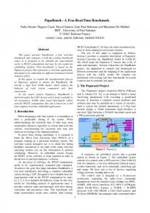
Techniques such as [Regan94] have been developed specifically to mask the latency introduced by the conventional graphics pipeline. However this particular technique only works for masking the rotational component of the viewing transformation leaving latency in the translational component of the viewing transformations. Other techniques have been developed to significantly reduce the latency induced by scanning out an image. For a 60 Hz display, the pixels at the bottom of the image are scanned out 16 ms later than the pixels at the top of the image. Olano et al. [Olano95] demonstrated that by changing the viewing transformation during scan out, this latency could be minimized. Their technique called "Just-In-Time Pixels" involves changing the viewing transformation slightly every scan line. It uses prediction and a simple approximation of the viewing transformation to mask scan-out latency. While this approach seems counter-intuitive for those used to dealing with frames, it does actually produce the right pixel at the right place at the right time. Provided the transformation is fast enough and smooth enough to avoid tearing, the technique works well. Tracking Geometry
0ms
Rasterize
17ms
Scan out
33ms
Decay
50ms
67ms
Conventional approach Tracking Decay
0ms
17ms
Just In Time Pixels approach Figure 1 Latency for the bottom scan line in a typical 3D graphics system vs. a "Just In Time Pixel" system. Images generated with a conventional 3D graphics pipeline have the same camera viewing transformation for all objects in the scene. To use a just-in-time pixels approach directly from a scene's geometry, a real-time ray tracer would be required. Otherwise, the scene's geometry would have to be pre-sorted into scan line order, then transformed and rasterized while "chasing the beam". In fact this in not a new idea as many of the earliest graphics systems used the "chase the beam" approach. Image-based rendering techniques seem much more appealing for changing the viewing transformation at scan-out rather than operating from geometry. Since pure rotations do not effect the occlusion within an image, image-based techniques have been developed to modify the rotational component of the viewing transformation late in the pipeline or at scan out [Regan94]. Translations do cause changes to occlusions within the scene, so modifying the translational component of the viewing transformation at scan out is much more challenging. Viewpoint interpolation techniques such as [Chen93, McMillan95] have
been developed to do this, however these techniques are generally suited to small translations and they can introduce visual artifacts where occlusion information has been lost. A newer image-based representation known as a "Light Field" [Levoy96] or "Lumigraph" [Gortler96] (from here on in we will use the term light field for convenience) is more suitable for this application than simple viewpoint interpolation. Light fields completely characterize the flow of light through unobstructed space in a static scene with fixed illumination. Hence viewpoint interpolation within a given region from a light field does not suffer from the same occlusion problems mentioned last paragraph. Section 2 of this paper briefly discusses light fields and the special case of the Levoy - Hanrahan geometry that is used to make the hardware version of the renderer. Section 3 discusses the architecture of the renderer and describes the low-latency hardware implementation. Section 4 discusses and provides the results of a human perception experiment while Section 5 of the paper describes future work and gives a conclusion.
2 THE LIGHTFIELD APPROACH A light field is a 4D function, that captures light rays between two surfaces. Levoy and Hanrahan, and Gortler et al. describe a parameterization method where the light rays are indexed by their intersection with these two surfaces. If we choose a special case of the Levoy - Hanrahan geometry where the focal plane coincides with the screen, an output image may be generated by re-sampling the light field in orientation but not position. The second projection in the Levoy - Hanrahan scheme is achieved by simply viewing the screen, replacing the quadralinear interpolation with a bi-linear interpolation.
when uncompressed. While compression schemes do exist and achieve significant compression ratios, schemes other than Vector Quantization (VQ) [Gersho92] are difficult to implement in real-time hardware. As a result, our initial implementation involves reducing the capture plane to a single axis, which eliminates vertical motion parallax. We refer to this as a 1-axis light field, giving a 3D light field rather than a regular light field which has a 2 axis capture plane resulting in a 4D function.
3 LOW LATENCY HARDWARE In order for a virtual object to appear stationary and accurately registered, two conditions must be satisfied. First, the user's viewpoint must be tracked accurately and with low latency. Secondly, the image must be computed and displayed with low latency. Any latency in the system causes objects to "swim" while the user's head is moving, potentially diminishing the illusion. A goal of this effort was to implement a low latency rendering scheme for "Fish Tank" virtual reality in order to study the effects of latency. We chose a light field representation for the object to be displayed with low latency. In principle, a light field can be sampled with a different tracking location for each display pixel or each display scan line, rather than just once per frame, making it suitable for the just-in-time pixels approach. To achieve this goal we actually built a low latency tracking system and a low latency hardware light-field renderer using a combination of custom and off-the-shelf components. We decided to build a “gold standard” system, which was specifically over-engineered to have the lowest latency we could reasonably achieve and significantly lower than we expected necessary. The system is depicted in Figure 3.
Screen Xright
Xlef
Viewing Location Sright
Sleft Capture Plane
Figure 2. Plan view of the geometry for the special case of the Levoy - Hanrahan light field. The Screen and the Capture Plane are the two surfaces used to create the light field. Projecting rays from the screen back through the viewing location to the capture plane gives us the s and t parameters for any x, y pixel location. From Figure 2 it can be seen by similar triangles that, s varies linearly with screen location based on the viewing location (t, the other axis not shown in Figure 2 also varies linearly with screen location). Hence for any given location, x and y correspond to the screen space location of a pixel and s and t are simple linear equations derived from the position of the screen and the viewing location. New s and t linear equation coefficients can be computed for every tracking sample. A disadvantage of the light field representation is the sheer volume of data required to represent a light field, especially
Figure 3. Using the light field renderer. Note the mechanical arm tracking the user’s head and the PC in the background which contains the custom hardware for the renderer. The system was designed to operate at 25 MHz, producing a Standard VGA signal. The user's head can be tracked rapidly and new light field parameters computed, and down-loaded to the hardware, at nearly 100 times per frame.
3.1 Tracking A great deal of work has been done to accurately track a user’s head for virtual reality and fish tank virtual reality. Schemes using a plethora of technologies have been developed and many
of these systems are commercially available. Technologies used for tracking a user’s head include magnetic systems, optical systems such as UNC’s hi-ball tracker [Welch97], acoustic systems and mechanical systems. To achieve minimal latency with high accuracy, we decided to use a mechanical system. In practice the main drawbacks of a mechanical system are the limited operating volume and the inertia introduced by the mechanical system. For the purpose of our experiment, where the user sits in front of a screen and moves from side to side, the restrictions of the mechanical tracker were tolerable. The main advantages of the mechanical systems are high accuracy, potentially very low latency and low cost.
The architecture for the light field renderer depicted in Figure 5 is very simple. It consists of a conventional raster generator for counting x and y, a light-field frame buffer, an interpolation unit for s, a linear interpolation filter, a stereo management unit and a video DAC. Each clock cycle, the raster generator increments x by one and s by δ s. At horizontal sync, y is incremented by one. Also at the horizontal sync, new values for s and δ s, are loaded into the interpolation unit. The x, y, s values are concatenated together to form the pixel address within the light field. The pixels at locations (x, y, s) and (x, y, s+1) are fetched simultaneously and blended together using the fractional parts of s.
From host
X
Raster Generator
Y
Light
S
Buffer
Pixel at X|Y|S
Blend
Video DAC
Field
sleft δ s
Pixel at X|Y|(S+1)
S interp. s = s + δs per clock (Set s Hsync)
=
sleft
Fractional part of S
at
Figure 5. Overview of the hardware light field renderer.
Figure 4. Inside the modified mechanical arm. The interface board allows the rotary encoders to be sampled at high speed. The tracker used for the light field renderer consisted of a modified MicroScribe mechanical arm from Immersion Corporation [Immersion99]. The arm has relatively low inertia and the manufacturers claim it is accurate to 0.3 mm. The MicroScribe arm uses rotary encoders at each mechanical joint to determine the orientation and location of the tip of the arm. The encoders are connected to counters inside the arm and the encoder readings are transmitted to a PC over an RS232 serial interface. Rather than rely on an RS232 serial link we built a custom interface board that transmits the encoder outputs in parallel to counters in the host PC (see Figure 4). The encoder counters are implemented in a Xilinx-based Field Programmable Gate Array (FPGA) on a custom PCI based board inside the PC. In the test system, the latency of reading the encoders and computing position and orientation information is approximately 64 µs.
3.3 Hardware Implementation The light field renderer has been implemented using two custom FPGA based rapid prototyping boards referred to as Programmable And Reconfigurable Tool Set (PARTS) boards [Woodfill97] (see Figure 6). Each PARTS board consists of 16 Xilinx 4028 FPGAs arranged in a 4 by 4 grid. The design uses two PARTS boards and operates at 25 MHz to produce a Standard VGA signal (60 Hz). Stereo is currently achieved using a red and green filter. The design can operate in mono mode or in stereo mode. Due to bandwidth limitations, the red green stereo mode operates in an interlaced manner.
3.2 Light Field Rendering Architecture To simplify the implementation of the light field renderer, it was decided that uncompressed light fields should be used. The custom hardware used to implement the architecture has a physical memory limitation of 32 Mbytes, thus as stated earlier, we decided to only implement a 1-axis light field rather than a 2axis light field. This means vertical motion parallax is eliminated while viewing the light field. Although this is undesirable, it still allows for meaningful latency tests to be carried out. While VQ decompression is well suited to a hardware implementation, even VQ decompression would not free up enough memory for a 2-axis light field on the current system. With 32 Mbytes of memory it is possible to store 128 gray-scale images of 512 by 512 pixels.
Figure 6 The PARTS board. Additional FPGAs are located on the other side of the board. The main reason for using an FPGA-based approach over a software implementation is that there is no final frame buffer in the system. The light field renderer directly drives the video DAC. The FPGA implementation guarantees data output for every pixel clock. It also guarantees the counters and interpolators will be incremented and updated at the appropriate times. A software-based implementation running on a system with an Operating System (OS) is not suitable for driving the beam directly, as any OS overheads would result in missed pixels. A large First In First Out (FIFO) buffer or a frame buffer
would be required to overcome this problem so that the swap time can be amortized over a large number of pixels. However the inclusion of such buffers requires additional hardware and increases latency. Conventional 3D graphics cards are designed to have a fixed viewing transformation for the entire frame and are not suited to the just-in-time pixels approach. The main tracking loop of the light field rendering system runs on the Pentium II PC host. It reads the rotary encoder counters from the FPGAs, converts these readings to a location for the arm, generates the linear equation for the light field for both the left and the right eyes. These values are then downloaded into the light-field renderer on the PARTS board. The measured end to end latency of the system is 200 µs, with an update rate of 5 kHz. On a sample by sample basis, s and δ s only change by a small amount. Although the update rate is less than once per scan line, no visual tearing in the light field was observed.
4 EXPERIMENTAL RESULTS We conducted a study to determine the point at which subjects could reliably detect latency in the display. This study involved twelve participants with normal or corrected vision. We ran a 2interval forced-choice staircase procedure [Levitt71] in which participants were asked to determine which of two intervals contained latency. The 2-down 1-up staircase routine yields the 70.7 percent correct point. Two staircases were randomly interleaved. The results of this study are depicted in Figure 7. The average latency threshold for the twelve participants was 15.0 ms, with a standard deviation of 3.1ms. Over multiple sessions, the user's threshold tended to decrease. Average Theshold by Subje ct
Thr esh old (m s)
25
enable the display of 2-axis light fields or motion sequences of 1-axis light fields.
Acknowledgements The authors would like to acknowledge Sheryl Ehrlich for designing and conducting the final version of the user study. We would like to thank Michael Bajura for his help with the mechanical tracking system, and Frank Crow and Philip Hubbard for their helpful suggestions. Finally we would like to thank the anonymous reviewers for their constructive criticism of the submission version of the paper.
References [Azuma95] Azuma, R., Predictive Tracking for Augmented Reality. UNC Chapel Hill Department of Computer Science PhD Dissertation 1995. [Chen93] Chen, S.E., Williams L., "View Interpolation for Synthetic Image Synthesis" Computer Graphics (SIGGRAPH '93 Proceedings), Vol. 26, 1992, pp 279-288. [Cutler97] Cutler, L.D , Frolich, B., and Hanrahan, P., "TwoHanded Direct Manipulation on the Responsive Workbench", 1997 Symposium on Interactive 3D Graphics, pp. 107— 114, 1997. [Deering93] Deering, M., "High resolution virtual reality", Computer Graphics (SIGGRAPH '92 Proceedings), Vol. 26, 1992, pp 195-202. [Gersho92] Gersho, A., and Grey, R.M., Vector Quantization and Signal Compression, Kluwer Academic Publishers, 1992. [Gortler96] Gortler, S.J., Grzeszczuk, R., Szeliski, R., and Cohen, M., “The Lumigraph”, Computer Graphics Proceedings, Annual Conference Series (SIGGRAPH 96), pp43-54. [Immersion99] Immersion www.immerse.com
20 15 10 m ean threshold
5 0 0
2
4
6
8
10
12
Sub ject #
Figure 7. Results from the user test. Note that 0ms latency really means less than 0.5ms. This experiment determined detectable amounts of system latency, when compared to a negligible latency system. In a practical application, users may tolerate or may not notice higher amounts of latency. When we refer to latency in the experiment, we are only referring to the computational component of the latency, leaving out the mechanical component and phosphor decay component.
5 CONCLUSION We have developed and implemented a graphics system architecture for displaying static light fields with very low latency. A user test of the system revealed an average detectable latency threshold of 15ms, although some users were able to detect 7.5 ms of latency. Below this threshold, the users perceived the graphical objects to be spatially stable. A new version of the system is currently being developed. This will
Corporation's
web
page.
[Levitt71] Levitt, H., "Transformed Up-Down Methods in Psychoacoutics", The Journal of the Acoustical Society of America, Vol 49. No. 2 (Part 2) 1971 pp467-477. [Levoy96] Levoy, M., Hanrahan, P., “Light Field Rendering”, Computer Graphics Proceedings, Annual Conference Series (SIGGRAPH 96), pp31-42. [McMillan95] McMillan, L., Bishop, G., "Head-Tracked Stereoscopic Display using Image Warping," Stereoscopic Displays and Virtual Reality Systems II, Proc. SPIE, Vol. 2409, S.Fisher, J. Merritt, B.Bolas eds. 1995, pp21-30 [Olano95] Olano, M., Cohen, J., Mine, M., Bishop, G., "Combatting Rendering Latency" 1995 Symposium on Interactive 3D Graphics, pp. 19— 24, 1995. [Regan94] Regan, M., Pose, R., "Priority Rendering with a Virtual Reality Address Recalculation Pipeline", Computer Graphics Proceedings, Annual Conference Series (SIGGRAPH 94), pp155-161. [Welch97] Welch, G., Bishop, G., "SCAAT: Incremental Tracking with Incomplete Information," Computer Graphics Proceedings, Annual Conference Series. (SIGGRAPH 97), pp333-344. [Woodfill97] Woodfill, J., and Von Herzen, B., "Real-Time Stereo Vision on the PARTS Reconfigurable Computer," Proceedings IEEE Symposium on Field-Programmable Custom Computing Machines, Napa, pp. 242-250, April 1997.