A Realtime Hardware System for Stereoscopic Videoconferencing with Viewpoint Adaptation Jens-Rainer Ohm1, Karsten Grüneberg1, Emile Hendriks2, Ebroul Izquierdo M.1, Dimitris Kalivas3, Michael Karl1, Dionysis Papadimatos4, André Redert2
ABSTRACT This paper describes a hardware system and the underlying algorithms that were developed for realtime stereoscopic videoconferencing with viewpoint adaptation within the European PANORAMA project. The goal was to achieve a true telepresence illusion for the remote partners. For this purpose, intermediate views at arbitrary positions must be synthesized from the views of a stereoscopic camera system with rather large baseline. The actual viewpoint is adapted according to the head position of the viewer, such that the impression of motion parallax is produced. The whole system consists of a disparity estimator, stereoscopic MPEG-2 encoder, disparity encoder and multiplexer at the transmitter side, and a demultiplexer, disparity decoder, MPEG-2 decoder and 1
Heinrich-Hertz-Institut Berlin, Germany.
2
Delft University of Technology, Netherlands
3
INTRACOM, Greece
4
University of Patras, Greece
The work described herein was performed within the ACTS PANORAMA project, funded by the European Commission under grant AC092.
Corresponding author : Dr.-Ing. Jens-Rainer Ohm Heinrich-Hertz-Institut Image Processing Department Einsteinufer 37, D-10587 Berlin, Germany Phone : +49-30-31002-617
Fax : +49-30-392-7200
E-mail :
[email protected]
interpolator with viewpoint adaptation at the receiver side. For transmission of the encoded signals, an ATM network is provided. In the final system, autostereoscopic displays will be used. The algorithms for disparity estimation, disparity encoding and disparity-driven intermediate viewpoint synthesis were specifically developed under the constraint of hardware feasibility.
Ohm/Grüneberg/Hendriks/Izquierdo/Kalivas/Karl/Pelekanos/Redert : -2-
A realtime hardware system for stereoscopic videoconferencing with viewpoint adaptation
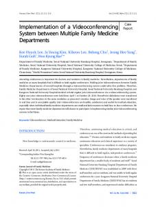
I. INTRODUCTION A telepresence videoconferencing system should give the users an illusion of true contact, bringing participants together in a virtual space. This cannot be achieved by an ordinary stereoscopic image acquisition/presentation chain. Firstly, the users should not wear glasses, which implies that autostereoscopic displays have to be used [1]. Second, the viewer would expect that the view angle alters with movements of the head ; this effect, called motion parallax, is very important for a true illusion of being inside a 3D scene. To achieve this, viewpoint adaptation must be performed, which means that the view angle on the display is altered automatically according to the viewer's head movements [2]. Third, the stereoscopic cameras cannot be positioned in front of the display, which implies that the baseline between the cameras must be at least 50 cm with a relatively small display, and 80 cm with a larger display. Such a baseline is by far too large for rendering stereoscopic images directly. The extreme differences between left- and right-view images do not correspond to the small distance of human eyes, and the resulting stereo presentation would perturb the viewer. Hence, it is necessary to synthesize intermediate-view stereo image pairs with smaller baseline (fig.1). At the same time, a headtracking system can be used to adapt the actual viewpoint on the interocular axis between the cameras, which gives the impression of natural motion parallax. A prototype hardware system, which will perform these tasks, is presently developed within the framework of the European PANORAMA project. The synthesis of natural-looking intermediate views can be done by interpolation from the leftand right-view images, if the positions of corresponding points are known. This requires the knowledge of depth information, which can be obtained by disparity estimation between the leftand right-view images. The disparity vectors can then be used to project pixels onto an intermediate image plane. However, a critical case is the presence of occlusion areas, where some parts of the scene may only be found in the left- or in the right-view image. In these cases, instead of interpolation, a unidirectional projection has to be performed. Furthermore, disparity estimation is not a trivial task due to the rather large baseline. We have found that horizontal disparity ranges of up to 120 pixel are necessary with a 50 cm baseline, and a distance of 1.5 m between the camera and the user. The vertical disparity shifts are much smaller. In the special case where a coplanar camera geometry is used (which means that cameras shoot in parallel directions and are adjusted at the same
Ohm/Grüneberg/Hendriks/Izquierdo/Kalivas/Karl/Pelekanos/Redert : A realtime hardware system for stereoscopic videoconferencing with viewpoint adaptation
-3-
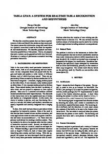
height), the vertical disparity is approximately zero all over the images. We decided to use this geometry in order to simplify the algorithms with respect to hardware realization. The paper is organized as follows. Section II introduces the concept of the whole system chain. In section III, the algorithm for disparity estimation algorithm is described. Section IV specifies the scheme developed for encoding of the disparity map. The algorithm for interpolation synthesis is introduced in section V. Section VI gives results of computer simulations and shows examples. Section VII describes the hardware concepts for the different parts of the chain. In section VIII, conclusions are drawn. II. SYSTEM CHAIN Fig.2 shows the complete system chain in schematic form. The transmitter side consists of data acquisition (stereoscopic camera, microphone), disparity estimation processing and encoding. The stereoscopic camera setup uses parallel camera geometry, which allows to reduce the disparity estimation search to the horizontal shift component. The disparity estimation processing also includes delays which are necessary to synchronize video, audio and disparity data prior to encoding, and a special disparity command conversion which is described in more detail in section IV. The left and right view image signals and the audio signal are encoded by separate, commercially-available MPEG-2 encoders. However, it is necessary to provide a separate encoder for the subsampled disparity fields that are output from the estimator. The system multiplexer, which is compatible to a standard MPEG-2 multiplex, integrates the encoded disparities as additional stream data, independent from video data. Furthermore, it is necessary to synchronize the independent left- and right-image video encoders and the disparity data. For transmission, a standard ATM network is provided. We are using constant rate transmission in AAL 5. At the receiver side, demultiplexing of video, audio and disparity data is performed first. Then, the separate elementary streams are fed into the appropriate decoders, of which only the disparity decoder is a non-standard device again. Video and disparity data are then fed into the intermediate viewpoint interpolator, which gets further information from a headtracking system about the required viewpoint. The information of the headtracker is used at the same time to drive the autostereoscopic display, which is a system based on projection onto a lenticular screen and must be adapted according to the viewing angle [3].
Ohm/Grüneberg/Hendriks/Izquierdo/Kalivas/Karl/Pelekanos/Redert : -4-
A realtime hardware system for stereoscopic videoconferencing with viewpoint adaptation
The system is designed such that it can work in three modes, and hence can also be configured in a flexible way for other purposes. In the direct mode, only data acquisition, estimator processing, interpolator processing and data presentation are performed, which is the basic configuration for a stereoscopic system with viewpoint adaptation. In coding mode, the chain is extended by the encoders, multiplexer, demultiplexer and decoder, which enables compression of the required data. In ATM mode, also a transmission of data is performed. III. DISPARITY ESTIMATION Disparity estimation is the most demanding task for the system hardware. To match the corresponding points between left- and right-view images, disparity ranges of up to 120 pixel are necessary, when the baseline is 50 cm and the distance between user and camera is 1.5 m. With 80 cm baseline, this range would even increase to approximately 230 pixel. Due to the use of a parallel camera geometry, the disparity estimator needs only to take into account the horizontal disparity shift. On the other hand, the parallel setup has the disadvantage that the absolute disparity shift between left and right images is much larger than the ranges given above ; specifically, the zero disparity is only met for a point with infinite distance. As a consequence, a large portion at the left side of the left image is not present in the right image, and a large portion at the right side of the right image is not present in the left image (see fig.3). This circumstance is taken into account during estimation by defining an additional disparity offset doff, and must also be treated during interpolation (see section V.2). During the last years, many different schemes for disparity estimation have been proposed. Though feature-based [4,5,6] and dynamic-programming [7,8,9] approaches seem to perform very well, we found them to be too complex for a hardware system with the requirement of large disparity ranges even in the case of pure horizontal disparities. Matching approaches can be classified as area-based schemes [10,11]. We have compared several algorithms (feature-based, dynamic programming and matching) with respect to subjective quality results and hardware feasibility, and decided to implement the hierarchical block matching scheme, which is described in this section. This scheme easily copes with arbitrary disparity ranges, and performs robust even in the case of low correspondence between left- and right-view images, e.g. in partially occluded areas. A criterion based on an absolute-difference feature is used to determine optimum positions of the
Ohm/Grüneberg/Hendriks/Izquierdo/Kalivas/Karl/Pelekanos/Redert : A realtime hardware system for stereoscopic videoconferencing with viewpoint adaptation
-5-
matching windows. At the same time, in a preprocessing stage, a simple foreground-/background segmentation is performed, which is used to refine the results of estimation. The disparity estimation algorithm can be divided into 4 different modules : 1. Preprocessing and segmentation. The goal of this stage is to find points with highest relevance for matching, and to perform a raw subdivision into foreground and background areas. 2. Block matching with large block size for global bidirectional disparity estimation, followed by a cross-consistency check. 3. Block matching with small block size for local bidirectional disparity estimation, followed by a cross-consistency check. 4. Interpolation of dense L→R and R→L disparity fields, application of vertical median filters and ordering-constraint check. A flowchart describing the interrelation of the disparity estimator module blocks is given in fig.4. Preprocessing and segmentation is performed on both input signals. Bidirectional (L→R and R→L) sparse disparity fields are estimated in the global and refined in the local estimation stage. In order to guarantee temporal continuity of the estimated disparities and to avoid temporally annoying artefacts, the disparities estimated for the previous field pair are fed back to the estimator stages. For this purpose, the dense field, generated at the final stage by bilinear interpolation, is used. III.1. Preprocessing and segmentation The preprocessing-and-segmentation stage uses a simple criterion based on pixel differences. To select those image points which cannot be distinguished from their neighbours, we use a simple, difference-based interest operator (see the so-called Moravec operator [12] in fig.5). This is applied to both left- and right-view image fields. The directional difference in four directions (horizontal, vertical and the two diagonals) is measured at each pixel position over a small square window of size 5x5. In each of the four directions, we have five pixels, and four differences between adjacent pixel pairs. In a first step, the sums-of-absolute-differences along all directions are calculated. The output of the operator is then defined as the maximum of these four sum values. The goal of this operation is two-fold : − The Moravec operator's output is used to detect the point of highest interest within each matching block for the subsequent global block matching stage.
Ohm/Grüneberg/Hendriks/Izquierdo/Kalivas/Karl/Pelekanos/Redert : -6-
A realtime hardware system for stereoscopic videoconferencing with viewpoint adaptation
− A threshold analysis detects large, uniform areas, at which valid disparity vectors cannot be estimated by a block matching strategy, because no true correspondences can be found. If we process head-and-shoulder scenes with relatively uniform background, it is easy to interpret this as a raw foreground/background segmentation. The classification is performed on block basis, where isolated areas with "wrong" classification are erased by comparison with their neighbors. In this case, we end up with a unique foreground/background mask containing only two segments. Actually, this system was only optimized for head-and-shoulder scenes with uniform background. In the future, it would be possible to replace this part by a more sophisticated algorithm, which enables a more precise knowlege about the borders between foreground and background areas, where abrupt changes in the disparities will occur due to occlusion effects. In the case where no reasonable foreground/background segmentation mask is found (the "foreground region" of the segmentation mask then covers the whole image), those features of the estimator, which are related to the segmentation mask, are switched off, while the overall system still keeps working with fair quality. Figures 6 and 7 show the extracted foreground regions from the left first frame of the sequences ANNE and CLAUDE, and the highest-variance points which are used as matching correspondences by the following global block matching stage III.2 Global disparity estimation In order to reduce noise sensitivity and simultaneously reach higher efficiency, both the left and right image fields are subsampled by a factor of two in the horizontal direction. Only those subsampled fields are used during the global estimation step, which are now divided into blocks of size 16x16 pixel. We use the point of highest interest within each block, which has been determined by the preprocessing module, and match a reference window of size MxN pixel around this point (fig.8). This means that the sampling position with highest omnidirectional difference inside the block is chosen as representative point for the entire block. Furthermore, matching is performed only for those blocks which are part of the foreground region from the segmentation mask (if present), which means that blocks within uniform background areas are not considered at all during the matching process. If the foreground region covers the whole image, matching is performed on all blocks.
Ohm/Grüneberg/Hendriks/Izquierdo/Kalivas/Karl/Pelekanos/Redert : A realtime hardware system for stereoscopic videoconferencing with viewpoint adaptation
-7-
Let z=(x,y) be the sampling position of the particular highest-interest point (center of the reference window) in the left field, that has been chosen to be matched. A full-search block matching in horizontal direction is performed in order to find the corresponding block centered z = ( x − d z( t ) − d off , y ) in the right field. Herein, d z( t ) denotes the absolute-valued around point ~ disparity vector from left to right at time t, and doff the predefined disparity offset (remark that the left-to-right shift is always negative with a parallel camera setup !). The reference window is compared with all corresponding windows (of size MxN as well) along the given horizontal search interval, defined by the disparity search range and the disparity offset. The disparity range is from 0 to 63, such that a maximum disparity shift of 126 pixel plus offset can be estimated with respect to the not-subsampled image field. In order to select the best match among the allowed displacements, a matching criterion based on temporal smoothing and mean absolute difference (MAD) is used. The MAD is given as
MAD(d z( t ) ) =
1 M⋅N
N /2
M /2
∑ ∑
j =− N / 2 i =− M / 2
I l ( x + i , y + j ) − I r ( x + i − d z( t ) − d off , y + j ) .
(1)
Using the MAD, the cost function is defined as:
F (d z( t ) , d z( t −1) ) = MAD(d z( t ) ) + α d z( t ) − d z( t −1) ,
(2)
with d z( t ) as current displacement vector, d z( t −1) the temporal prediction vector and the weight coefficient α, which should be set to an approximate value of 0.2. The block sizes were set to M=13 horizontally and N=9 vertically for the local matching stage. To realize a simple hardware structure, the quotient 1/117 was omitted from (1), and α was set to 16 in (2). The temporal prediction vector d z( t −1) is taken from the same position z in the previously-estimated disparity field at time t-1. The previous-field dense disparity maps are available from the dense-field interpolation module, which are stored internally. For each position ~ z within the search interval, the function value F (d z( t ) , d z( t −1) ) is calculated. The particular sampling position ~ z , which minimizes this cost function, is the corresponding point of z. Once ~ z has been estimated, the same procedure is repeated from right to left, using ~ z as
Ohm/Grüneberg/Hendriks/Izquierdo/Kalivas/Karl/Pelekanos/Redert : -8-
A realtime hardware system for stereoscopic videoconferencing with viewpoint adaptation
reference sampling position on the right image, which means that the reference window of size MxN is now centered at this position. The search window of the same size is placed on the left image and shifted within a search interval of 64-pixel width again. Now, the temporal prediction is taken from the R→L dense disparity memory. The correspondence search is then carried out without further consideration of the previously-found L→R disparity d z( t ) .
MAD(d ~z( t ) ) =
1 M⋅N
N /2
M /2
∑ ∑
j =− N / 2 i =− M / 2
Ir (~ x + i , y + j ) − I l ( x~ + i + d ~z( t ) + d off , y + j ) .
(3)
Using the MAD, the cost function is defined as:
F (d ~z( t ) , d ~z( t −1) ) = MAD(d ~z( t ) ) + α d ~z( t ) − d ~z( t −1) ,
(4)
Let us denote the estimated L→R disparity with z as reference sampling position as d z( t ) , and the estimated R→L disparity with reference sampling position ~ z = ( x − d z( t ) − d off , y ) on the right image as d ~z( t ) . Then, a bidirectional consistency check [13] is performed in order to reject outliers. If the vector difference condition
d z ( t ) − d ~z ( t ) ≤ 1 pel
(5)
is violated, the two vectors d z( t ) and d ~z( t ) are eliminated from both sparse disparity fields. This verification enables a reliability criterion of disparity estimation, such that the remaining disparity estimates can be considered as correct disparity values. III.3 Local disparity estimation Local disparity estimation is also a block matching procedure, but is applied to the full-resolution (not-subsampled) image fields. The block center positions z=(x,y) are now 4 pixel apart in the horizontal and vertical directions. The reference windows have a size of M=9 pixel horizontally and N=5 pixel vertically, but the position z is always at the block center, such that adjacent windows overlap by a regular value. Instead of using full search (as in global estimation), only the range
Ohm/Grüneberg/Hendriks/Izquierdo/Kalivas/Karl/Pelekanos/Redert : A realtime hardware system for stereoscopic videoconferencing with viewpoint adaptation
-9-
defined by candidate vectors is tested with an additional search range of ±2 pixel horizontally beyond the minimum and maximum candidates. We are using 10 candidates, of which are − 6 from the output of the global estimation, unless they are part of the background segment ; − 3 candidates from neighboring blocks, which were already calculated during local estimation; − 1 from the temporally-preceding displacement field at the same spatial position. The positions of candidates and the procedure of search range determination are illustrated in fig.9. Herein, the matching windows used during global matching are marked as hatched regions, with the center anywhere within the global block areas of size 32x16 (this is the not-subsampled equivalent of the 16x16 block size used during global estimation). Global candidates are the one that belongs to the active area (of which the actual local block is part), and in addition its left/right neighbors and the three neighbors below. It may happen that neither a global, nor a local candidate exists. This will be the case, e.g. when all candidates are within uniform background areas, or if they did not pass the bidirectional consistency check. In addition, the search range is cut by all disparities which would point into the background part of the opposite field's segmentation mask. In the case where less than 4 positions would have to be checked, no matching is performed, and the positions in the sparse disparity field are a priori marked as INVALID. Those candidates, which originated from global matching, have to be multiplied by two, because they were calculated on the basis of subsampled images. The search range of the local matching procedure is determined on the basis of all candidates. For this purpose, the minimum (MIN) and maximum (MAX) disparity values among the candidates are determined, and the search range reaches from MIN-2 to MAX+2, but is limited between 0 and 127. The rest of the procedure is very similar to global estimation (1)-(4), with exception of the search range(s) and block sizes. Again, the search criterion is a combination of MAD and temporal smoothness with approximately the same α-parameter (≈0.2) in (2),(4). In order to omit the division in (1),(3), where the quotient should now be 1/45, α was set to a value of 8. Local displacement estimation is also performed bidirectionally, in order to apply the crossconsistency check (5) on the estimation result. As the first step, L→R disparity estimation is performed. Hence, the positions z in the L image field are equidistant, while the best-matching positions in the R image field are not necessarily equidistant, but anywhere on the same line. Sparse disparity fields are generated with valid values at each fourth row. For R→L disparity estimation, the same search range is used as for L→R estimation. Ohm/Grüneberg/Hendriks/Izquierdo/Kalivas/Karl/Pelekanos/Redert : -10-
A realtime hardware system for stereoscopic videoconferencing with viewpoint adaptation
Regarding the output of the estimation, the number of disparity values calculated per image field is not fixed. This is caused by possible INVALID values in the sparse disparity field. The maximum possible number of estimated disparity values is 1/16 of image field size. Another object-based postprocessing step is performed if a foreground/background segmentation mask exists. Among the first four valid disparity values at the left and right sides of the foreground part of the mask, it is checked whether the absolute disparity is smoothly decreasing towards the outermost one. If this is not the case, those values are eliminated (set to INVALID), which offend this condition (indicated by broken lines in fig.10). III.4 Generation of rowwise-dense disparity fields After estimation of disparity values at sparse positions, as it is finally performed by the local estimation procedure, the dense disparity fields are generated by bilinear interpolation. Herein, we simply ignore the INVALID positions within the sparse disparity fields and generate the dense fields only from valid ones. The bilinear interpolation is at this stage performed only horizontally, within the rows where the local disparity estimation derives disparity values. This is called the rowwisedense disparity field, which is defined for rows 2,6,10,... of the image fields. This rowwise-dense field is used exclusively for the feedback (temporal prediction) of disparities during estimation. Furthermore, an extract from both rowwise-dense (L→R and R→L) fields is transformed into a unique command map representation for encoding, which will be described in the next section. After the interpolation, a vertical 7-tap median filter is applied to both disparity fields at these rows, i.e. the median mask contains the values at the same x-positions from each 3 rows below and above the actual point in the rowwise-dense disparity field (see fig.11). This median filter is necessary to reject outliers, and to introduce vertical dependencies between the estimated disparity values, which were so far calculated more or less independent of each other. If there are any remaining rows in the rowwise-dense field, which do not contain any valid disparities at all (this happens, e.g. in the case of a present segmentation mask, usually at the top of the image), these are filled by a vertical linear interpolation, again starting with a zero value at the top border. In fig.12, images representing the horizontal component of dense disparity field pointing from left to right are displayed for the tenth frame pair of sequences ANNE and CLAUDE. Low gray levels represent large negative horizontal vector components, whereas high gray levels represent large positive horizontal vector components. A vector with horizontal component 0 is represented by the gray value of 128. Ohm/Grüneberg/Hendriks/Izquierdo/Kalivas/Karl/Pelekanos/Redert : A realtime hardware system for stereoscopic videoconferencing with viewpoint adaptation
-11-
IV. DISPARITY MAP ENCODING In our system, the information about the disparity map must be transmitted along with the encoded data stream for the left and right camera signals. This is reasonable, because in multipoint videoconferencing it would be superfluous to determine the disparity parameters for all participants at each site. For the purpose of disparity map encoding, a new type of command map representation has been developed, which is easily compressible and bears information about both (L→R and R→L) disparity maps [14]. To transform disparities of the rowwise-dense field into the command map representation we are using, several constraints are imposed onto the disparity fields : − Only horizontal shifts can be treated (this was already a constraint from estimation) ; − The disparity map must obey the ordering constraint, i.e. disparities within one line must not cross each other ; − The disparity map must be absolutely dense, i.e. no special treatment of occlusions is performed (this demand is already fulfilled by the interpolation described in the last section). IV.1 The Disparity Command map If Dl( t ) ( x ) is the L→R absolute-valued disparity at pixel position x and time t, and Dl( t ) ( x −1) that of the previous pixel position (same with Dr( t ) for the R→L field), then the ordering constraint is violated, if Dl( t ) ( x − 1) − Dl( t ) ( x ) < 1 ; Dr( t ) ( x − 1) − Dr( t ) ( x ) > 1 .
(6)
If the constraint is violated once at position x1, the check must be iterated setting x←x+1, until a value is reached, which does not any more violate the condition Dl( t ) ( x1 ) − Dl( t ) ( x ) < x − x1 ; Dr( t ) ( x1 ) − Dr( t ) ( x ) > x − x1 .
(7)
Fig.13 shows an example of a disparity map violating the ordering constraint (a) and the correction (b). The command map, which is a transformed representation of the ordering-constraint checked disparity map, indicates where the correspondences can be found between the left and right image field. Two commands "match left" (ML) and "match right" (MR) are used, that indicate the
Ohm/Grüneberg/Hendriks/Izquierdo/Kalivas/Karl/Pelekanos/Redert : -12-
A realtime hardware system for stereoscopic videoconferencing with viewpoint adaptation
propagation of corresponding points along the scanlines of the left and right image fields. If the correspondence "halts", e.g. a number N of points of the left image are referenced to the same point in the right image, N subsequent ML commands are produced. This case we call a "left contraction". The other way round, in the case of a "right contraction", several subsequent MR commands are released. In the "normal" case, where disparity remains constant along the scanline, the sequence alternates ML-MR-ML-MR-... . An example is illustrated in fig.14. Starting at the left border of the images, which is position 0 in the right image, there is one correspondence to the left image at the same position (this will always be present, and must not be explicitly encoded), and 4 more correspondences to subsequent positions in the left image. Hence, the command map starts with four ML commands, which characterize the four additional correspondences of four left positions to the right position zero. Then, the correspondence proceeds one position in the left image (ML), and in the right image, too (MR). This happens once more, but then two additional MRs fit to the same left position. Finally, there is again one ML and three MRs. The complete command sequence for the example shown here is ML-ML-ML-ML-ML-MR-ML-MR-MR-MR-ML-MR-MR-MR. The total number of commands per scanline is 2⋅xsize-2, where xsize is the number of pixels in the scanline. The transformation from the disparity map to the command map is very simple. Suppose we are using the L→R disparity field. Since the estimator does not allow any disparities to point outside the image, and the dense field interpolation always starts with zero disparity at the borders, the disparity value of the first position of the scanline (x=0) will be zero. Now, whenever the disparity value at position x+1 is larger than the value at x, we have the case of left contraction ; if it is smaller, we have the case of right contraction, if it is equal, we have the normal case. Specifically, the number of ML commands to be released before the next MR command is equal to Dl( t ) ( x + 1) − Dl( t ) ( x ) + 1 in the case of zero or positive difference, and the number of MR commands to be released before ML is equal to Dl( t ) ( x ) − Dl( t ) ( x + 1) + 1 in the case of negative difference. It is easy to see that this automatically corrects disparity fields violating the ordering constraint (6),(7). For the R→L field, everything inverts ; a smaller disparity value at the next position indicates left contraction, a higher value the right contraction. It is left to the interested reader to determine the setting of ML and MR commands. Basically, both disparity fields contain approximately the same information, and are highly redundant due to the application of the bidirectional consistency check. Major differences may be present in the areas of heavy contractions (being in most cases originally occlusions), which are
Ohm/Grüneberg/Hendriks/Izquierdo/Kalivas/Karl/Pelekanos/Redert : A realtime hardware system for stereoscopic videoconferencing with viewpoint adaptation
-13-
indicated by many L→R (R→L) vectors pointing to only one or a very small number of pixels in the right-view (left-view) image. Indeed, we found that R→L disparities produced by the estimator algorithm are more reliable at left occlusions, while the L→R disparities produce better interpolated image quality at the right occlusions. Since we deal with videoconferencing sequences, we can employ a very simple model for head-and-shoulder scenes, which is based on the convex surface of the human head and body [11]. Then, it is clear that left occlusions can occur only left from the center of the foreground shape, while right occlusions will be present only at the right side from this point. Hence, we can divide each scanline of disparity values into two parts, which are marked by the mid position of the active area under the foreground object (fig.15). For the left part, the R→L disparity field is used, while for the right part, the L→R field is better suited. The split position is determined only from one of the masks (preferably R, since we start with this field), because the mid positions must not necessarily coincide. In addition, it is required to perform an orderingconstraint check at the crossover point, taking into account both fields. If no segmentation mask is present, the fallback mode is switched, which uses only one disparity field. As the estimation process is started with the L→R field, we chose to use this one. IV.2 Encoding of the Command map The command map is a compact representation of a disparity field checked for ordering constraint, and has an extremely small amount of inter-symbol redundancy [14]. With two commands, we need 2⋅xsize-2 bits per scanline to represent the command map. With CCIR-601 video (P=720), this results in a transmission rate of 5.177 Mb/s, if we transmit disparity values only at each fourth scanline. Since we have a maximum of 4 Mb/s allocated for lossless transmission of disparity values in our overall system, further reduction of data rate is necessary. We have found a Lempel-Ziv based algorithm [15] capable to reach a further reduction of rate by a factor of approximately two ; this algorithm can easily be implemented in realtime hardware, using a conventional microcontroller. The reason for further redundancy reduction is firstly the limited disparity range, which does not allow arbitrary command map sequences, but even more important are the interline, intraline, and temporal redundancies of the disparities, which are caused by the smoothness of object surfaces, and allow the code adapt to specific preferable ML/MR sequences. The encoding algorithm takes into account these characteristics. The update heuristic uses the frame being coded and the previous frame to update the Lempel-Ziv algorithm sequence memory. Sequences of ML/MR commands from lines adjacent to the line being coded and corresponding Ohm/Grüneberg/Hendriks/Izquierdo/Kalivas/Karl/Pelekanos/Redert : -14-
A realtime hardware system for stereoscopic videoconferencing with viewpoint adaptation
lines in the previous frame have been assigned a gradually increased priority over sequences gained from the rest of the sequence memory. Thus, during the coding process, these sequences are used first to compress the incoming command sequences. Tests have shown that even by limitation of the memory to these "near" sequences, the compression is not greatly affected : The compression degradation incurring through reduction of possible sequence memory positions is more than offset by the reduction of the absolute number of positions, which must be represented by specific codes. Limitation of sequences also reduces the hardware complexity. V. INTERMEDIATE VIEWPOINT INTERPOLATION The task of the interpolator is to generate two images from virtual cameras, based on two images from real cameras and their disparity map. The position of the virtual cameras should be related to the position of the viewer’s eyes. We have developed an interpolation concept which can decide dynamically, based on the degree of contraction, which areas of the intermediate image are truly interpolated, i.e. taken from both images, and which areas are possibly subject to occlusions and hence must only be projected from the corresponding area of one of the left- or right-view images. The unique representation of disparities by the command map has three advantages that can be exploited by the interpolator : − the vertical interpolation of the missing rows of disparities (the rowwise-dense map being defined so far only at each fourth row) is very simple using the command map ; − the determination of pixel addresses for the corresponding points, necessary during interpolation, can be performed only by increment operations ; − it is very easy to check the grade of contraction (multiple correspondences to one point), to decide whether it is more appropriate to perform extrapolation from one image instead of interpolation from both.
Fig.16 shows the block diagram of the interpolator. We can recognize four main parts: − Command expander − Parameter controller − Left eye image generator − Right eye image generator
Ohm/Grüneberg/Hendriks/Izquierdo/Kalivas/Karl/Pelekanos/Redert : A realtime hardware system for stereoscopic videoconferencing with viewpoint adaptation
-15-
The command expander transforms the four times subsampled command map to a dense (not subsampled) map by linear interpolation. The parameter controller generates control parameters for the image generators, e.g. the relative position of the virtual cameras. The right- and left-eye image generators are the actual image interpolators. V.1 Command expander The task of the command expander is to transform a four times vertically subsampled command map into a dense command map. To do this we need both interpolation and extrapolation of the command map. In the following example we will explain how to use these two options. Scanlines are numbered from 0 to 287 for each field. Since the original command map is sampled for example at scanlines 2, 6, 10, …, and 286, the lines 0 and 1 have to be extrapolated from line 2, line 287 has to be extrapolated from line 286, and all other lines have to be interpolated from the two lines that enclose them. All remaining lines have to interpolated. For this we use linear interpolation. This operation is very easily done with the two-command map. Let us consider two consecutive scanlines in the subsampled command map at positions y and y+4. We are going to create an intermediate command scanline at relative position α. For α=0, the scanline at position y is found, for α=1 the scanline at y+4. So, for our application, the values α = ¼, α = ½ and α = ¾ are used. The command map scanlines describe disparity paths. Fig.17 shows the two original disparity paths A and B in black and an interpolated one I in dark grey with α = ½. The axes are the horizontal positions of the left and right image scanlines. The disparity paths go from (0,0) to (719,719) in this diagram. The method of interpolation is very simple. We start at (0,0) for all three paths at time instant zero. At every time instant, we execute one command of each original command scanline. These commands we call ACOM and BCOM. They can be either ML or MR. An ML means a step in the left image scanline, in fig.17 this is a horizontal step from left to right. An MR means a step in the right image scanline, in the figure this is a vertical step from bottom to top. For the I command scanline we construct a command by ICOM = (1-α) * ACOM + α * BCOM. This gives us the analytical interpolated I path. For α unequal to 0 and 1 but in between, intermediate types of commands arise for the I path, other than ML or MR. The consequence of this is, that the analytical I path does not fit onto the grid in general. It can no longer be described by the normal commands ML and MR. We solve this by Ohm/Grüneberg/Hendriks/Izquierdo/Kalivas/Karl/Pelekanos/Redert : -16-
A realtime hardware system for stereoscopic videoconferencing with viewpoint adaptation
rounding off the path to the nearest grid point. The disparity path in light grey shows a rounded version of the original I path in dark grey. Although the rounded light grey path is used for output, the analytical dark grey path has to be calculated as well. If not, round off errors in the path will accumulate very fast. As the analytical path is constructed step by step at each time instant, the rounded path can be constructed by choosing either ML or MR. The goal is to minimize the distance between the endpoints of the current analytical and rounded path. V.2 Parameter controller Fig.18a/b shows as an example the left and right camera image of the MAN sequence, first frame. Fig.18c shows the associated command map disparity field, where the ML command is indicated as black, MR as white, and the "normal" alternation of ML-MR as grey. Fig.19 illustrates, for the example of one scanline at the tip of the nose of these images, some important preliminaries that have to be observed by the interpolator and must be regulated by the parameter controller. The scanline showing grey values from the left camera is located on top, that from the right camera at the bottom. All corresponding points are connected as they were found by the disparity estimator. The representation of fig.19 is very closely related to image interpolation : Every horizontal cross section gives the luminance values along the scanline of a virtual camera at a specific position between the real cameras. This relative position is indicated by the parameter S, which varies from -½ (position of left camera) to ½ (position of right camera). For the stereoscopic presentation, we take two virtual cameras with positions S1 and S2, S1 < S2, which are the positions of the virtual left and right cameras, respectively. If a stereoscopic scene shall appear behind the display, the nearest point must have a disparity shift of zero. However, in our parallel camera configuration, the nearest point has the largest disparity shift dmax, such that it is necessary to introduce a shift correction. Moreover, we must guarantee that the position of that point on the screen remains the same when the view angle is changed. Hence, the shift relative to the right camera at a specific position S, as it is shown in fig.19, must be SHIFT = d max ⋅ ( 12 − S )
(8)
pixels to the right. In this example, the nearest point is the lightest value, which is the tip of the nose. Ohm/Grüneberg/Hendriks/Izquierdo/Kalivas/Karl/Pelekanos/Redert : A realtime hardware system for stereoscopic videoconferencing with viewpoint adaptation
-17-
Now, the algorithm has two input parameters: the relative virtual camera position S and the shift parameter SHIFT. The S parameter is a real number between -½ and ½, the shift parameter an integer that can be both positive and negative, depending whether the left or right camera position is interpolated. Due to the horizontal shift, it is possible that some pixels on the virtual scanline are not in the visible region. In the example of fig.19, this is the case for the rightmost pixels. Using information from the visible region to define the luminance and chrominance of these pixels is not feasible. Therefore, we chose to set these pixels to black values. Specifically, it is necessary to set dmax pixels to black value at the left side of the left-view image (if S=-½ is selected) and do the same with dmax pixels at the right side of the right-view image (if S=½ is selected). At intermediate positions, the number of black pixels BLACKleft at the left side is equal to SHIFT from (8), and the number of black pixels BLACKright at the right side is equal to dmax-SHIFT. The parameter controller has to generate two sets of each four parameters, one for the left eye image generator and one for the right eye image generator. The headtracker information is vital for this. The information of the headtracker are the real numbers X, Y and Z. At this moment, we are using only the X component (left/right head position), which has the same scale as S. Furthermore, we need to define the real number DIST that is related to the eye distance and the camera baseline. This gives the relative distance between the viewpoints S of the left and right virtual cameras. A value of DIST=0.05 is presently set. We still investigate a technique to adapt this parameter to the Z information of the headtracker, which is the distance between display and viewer. We now redefine the SHIFT parameter given in (8), such that zero shift is now obtained at position S=0. All generated images with S0 are shifted towards right. At the same time, we assume that the blackening of pixels is performed after the shift, such that always dmax/2 pixels are set to black at both sides of the images. The following control parameters are then used:
Left control parameters S1 = x − 12 ⋅ DIST ; SHIFT = d max ⋅ S1
(9)
Right control parameters S 2 = x + 12 ⋅ DIST ; SHIFT = d max ⋅ S 2
(10)
Ohm/Grüneberg/Hendriks/Izquierdo/Kalivas/Karl/Pelekanos/Redert : -18-
A realtime hardware system for stereoscopic videoconferencing with viewpoint adaptation
Note that the two S parameters should always be in the range of [-½,½]. For extreme DIST values, S has to be clipped. Fig.20 shows the effect of the linear relation between the S and SHIFT parameter. The black parameters are chosen just large enough to ensure that always the same set of pixels on the virtual scanline is visible, independent of position S. V.3 Image interpolators Fig.21 shows one scanline of left and right images, their associated disparity field and an intermediate virtual image. For each 2 pixels in all images, we have two Y values, one U and one V value. For each virtual Y-pixel, we determine which disparity vectors cross its area. Of those, we select the ones most to the left. In the figure these are indicated by grey lines. After selecting a disparity vector, we determine which Y-pixels of the left and right image are referenced by this vector, and use a weighted average to create the value of the virtual Y-pixel: Yvirtual = Wleft ⋅ Yleft + Wright ⋅ Yright
(11)
The same procedure is done for U- and V-pixels, the only difference being that these components have only half the size, and double number of disparities values is defined for each pixel area. The generation of virtual Y-, U- and V-pixels are separate processes and can be done in parallel. In formula (11), two weights Wleft and Wright were introduced. Since the condition Wleft+Wright=1 must apply, we need to specify only one. For example, if we set Wleft=½, the interpolator would be most simple ; however, to obtain better image quality, it is required to take into account the position parameter S, and the contractivity of the disparity field described by the command map. The first can be done by setting Wleft =
1
2
−S,
(12)
which for extreme virtual camera positions |S| ≈ ½ produces much better results. An extension to this scheme is to make the weights dependent on the disparity field. If done correctly, it is possible to adjust the weights in such a way that in occlusion areas data is only taken from one image. In a two command disparity map, we can not see the difference between an occlusion and a strong
Ohm/Grüneberg/Hendriks/Izquierdo/Kalivas/Karl/Pelekanos/Redert : A realtime hardware system for stereoscopic videoconferencing with viewpoint adaptation
-19-
contraction. However, in both cases it would be wise to take data only from one of the left and right images. To accomplish this, we use again the notion of the disparity path. Fig.22 shows a disparity path representation of the disparity map scanline in fig.19. The horizontal and vertical axes are the horizontal positions of the left and right image scanlines, respectively. Each point in this representation corresponds to a possible match. The grey values indicate the probability of each possible match. The disparity path goes from (0,0) to (719,719) for CCIR601 images. Each disparity vector is one white point. The disparity range (allowed minimum and maximum disparities) is also shown in white. Next, we introduce the real number δ that indicates, for each disparity vector, the average direction of the disparity path in a window around that vector. The length of the window is the even integer N, and count(ML) is the number of ML commands in that window :
δ = 2⋅
count( ML) −1 N
(13)
In left occlusion or strong left contraction areas, δ becomes +1, indicating a horizontal path in fig.22 around the point of interest. In right occlusion or strong right contraction areas, δ becomes -1, indicating a vertical path in fig.22 around the point of interest. Now, we choose the weight Wleft to be: Wleft = W + δ ⋅ ∆W
(14)
with W=
1
2
− S ; ∆W =
1
2
−S
(15)
It is easy to see that Wleft = 1 in a left occlusion, Wleft = 0 in a right occlusion and Wleft = W for a normal object. This kind of adaptive weight setting is very easy to implement in hardware. Fig.23 shows the effect of the disparity-driven weighting procedure. Fig.23a is the weighting according to (12), with white indicating Wleft = 1 and black indicating Wleft = 0. Fig.23b shows the disparity-
Ohm/Grüneberg/Hendriks/Izquierdo/Kalivas/Karl/Pelekanos/Redert : -20-
A realtime hardware system for stereoscopic videoconferencing with viewpoint adaptation
adaptive weighting according to (14)-(15) with a window length N=8, and fig.23c with a window length of N=64. It can clearly be seen that Wleft approaches 1 even for S→½ in the areas of left occlusions (left side of the head), and Wleft approaches 0 even for S→-½ in the areas of right occlusions with adaptive weighting. In these areas, the disparity-weighted interpolation algorithm produces sharper images than the simple interpolator using (12). VI. EVALUATION OF ALGORITHMS AND RESULTS OF COMPUTER SIMULATIONS In the start phase of the PANORAMA project, we have compared different algorithms for disparity estimation and viewpoint interpolation with regard to subjective quality and hardware feasibility. Among the disparity estimators were a feature-based approach [16], two dynamic-programming approaches and the hierarchical block matching, which is described in this paper. The latter one was finally selected, because it showed superior performance and did not require larger hardware complexity than any of the other proposals. Two interpolation concepts were investigated, one of these an object-based approach [17], the other one the concept presented in this paper. Though the former one performed slightly better in the areas of conclusions with uniform background scenes, the latter one was selected, because it is less complex with respect to hardware realization, and more universal applicable also to non-uniform background scenes. The subjective assessments of six expert viewers were evaluated ; a "good" picture quality was attested to the selected scheme. The performance of the methods presented in this paper has been tested with a set of natural stereoscopic sequences in extensive computer simulation experiments. These sequences were recorded within the framework of the European projects RACE-DISTIMA and ACTSPANORAMA. The image resolution is 720x576 pixels. The stereoscopic sequences M AN, ANNE and CLAUDE, representing typical videoconferencing situations, are given here as a reference. It is interesting to note that these three sequences were taken with different camera setups. While MAN is truly in the configuration we are planning to realize (parallel cameras, but only the overlapping area is shown), the ANNE images were artificially shifted in order to avoid the large non-overlapping area between left and right image view. In both of these images, the baseline was 50 cm, with a distance of 2-2.5 m between cameras and person. The CLAUDE sequence was even captured with a convergent (non-parallel) camera setup, however with a much smaller baseline (15 cm), but also with smaller distance between person and camera (1.2 m). All the sequences presented here fulfil the uniform background assumption, such that the foreground/background segmentation can be
Ohm/Grüneberg/Hendriks/Izquierdo/Kalivas/Karl/Pelekanos/Redert : A realtime hardware system for stereoscopic videoconferencing with viewpoint adaptation
-21-
performed as planned in the hardware system. However, the disparity estimation algorithm did succeed not only with these sequences, but has also successfully been applied to other (non-uniform background) sequences. All underlying disparity estimation experiments have been performed using the parameters given in section III. Some results illustrating the performance of the image interpolation method are given in figures 24-26, which show left-view images, synthesized central viewpoints and right-view images using the tenth frame pairs of the sequences MAN, ANNE and CLAUDE. The computed central viewpoint is displayed between the two original stereo images. We obtain a good stereoscopic virtual-viewpoint image quality, when the difference in the sposition between a synthesized left- and right-view image is between 0.05 and 0.1, which corresponds approximately to the "natural" disparity due to the distance of human eyes. It is remarkable, that some occasional distortions, which become visible as some kind of temporal flicker near the foreground/background borders in a monoscopic presentation, are becoming unnoticeable in the stereoscopic view. The telepresence illusion is very natural, rendering high image quality. Recently, we have also tested the performance of the system with sequences, that were taken with a convergent camera setup. Herein, the preliminary condition is violated, that no vertical disparities should be present, which implies that the actions of the disparity estimator and the viewpoint interpolator should strictly not be limited to only one scan line. However, we have found that the quality of images interpolated with our system remains high, if the convergence angle between the camera is not too large (up to 15 degrees). With a convergent camera setup, the SHIFT parameters in (8) (9) and (10) can drastically be lowered, such that it is no longer necessary to set a large number of pixels at the left and right sides of the image to black values. This implies that we can utilize a larger area of the images, and can increase the size of the person by using cameras with larger focal length. VII. HARDWARE STRUCTURE
VII.1 Disparity estimator We have started hardware implementation of the disparity estimation algorithm with the overall structure that was shown in fig.3. The goal was to build a target hardware without dedicated chip
Ohm/Grüneberg/Hendriks/Izquierdo/Kalivas/Karl/Pelekanos/Redert : -22-
A realtime hardware system for stereoscopic videoconferencing with viewpoint adaptation
design, such that only custom chips, digital signal processors (DSPs) and field programmable gate arrays (FPGAs) were to be used. While the preprocessing and postprocessing (interpolation) stages can easily be realized within FPGAs, the matching stages give the most demanding task with respect to processing power. Nevertheless, we found it feasible to implement the matching kernel of the global stage by using one FPGA and one DSP. An additional FPGA is needed for pixel access control. The basic structure is similar to the local block matching module, which is indeed more complicated and will be described with more detail in the rest of this section. Figure 27 shows the hardware architecture of the local block matching module in more detail. Input data of this module are luminance of left and right video image and estimates of the global disparity vectors for a number of feature points. All input data form a multiplexed CCIR 656 data stream, where left and right video replace the luminance and chrominance data, and feature point coordinates as well as estimated global disparity vectors are transmitted in the horizontal blanking interval. Signal processing on the local block matching board is divided into several modules: two block matching modules, one 7-tap median filter module, and three DSP modules. Mechanical and electrical specification of all six modules and their connectors comply with the TIM-40 standard [18] to make interfacing and testing easy. While the DSP TIM-40 modules are commercially available, the other three modules are developed especially for the needs of this project. The complexity of present high-end FPGAs allows the design of a FPGA-based block matching processor containing 20 cell elements for parallel MAD calculations as well as additional circuitry for pixel addressing and MAD postprocessing. The applied principle of MAD calculation is the parallel accumulation of absolute pixel differences by shifting measure pixels. As depicted in figure 28, the cell array contains 20 block matching cells, each calculating the MAD for a single search position and passing on the measure pixel to the next cell. Thus, search pixels (S t) and measure pixels (Mt) have to be fetched only once for the complete estimation of a single block. The block matching processor is depicted in figure 29. It interacts with a DSP for provision of parameters used for address generation and MAD postprocessing, and with a dual-port memory which sequentially stores both left and right image slices and outputs left and right pixels for matching blockwise. The cost function is performed by an addition of the MAD and a counter register which is preloaded with the temporal prediction vector. Thus, the expression α|dz(t)-dz(t-1)| is built by decrementing or incrementing the counter register. The last step of finding the minimum of
Ohm/Grüneberg/Hendriks/Izquierdo/Kalivas/Karl/Pelekanos/Redert : A realtime hardware system for stereoscopic videoconferencing with viewpoint adaptation
-23-
the cost function requires the presence of a vector mask, which defines the valid positions to be taken into account for the search. The mask is provided by the DSP and results from ten start vectors for local search and the start vector transmitted to the processor. As depicted in figure 30, the estimation algorithm allows a parallel connection of BlockMatching Processors, each calculating a separate image slice. The parameters used for local disparity estimation require four processors working in parallel to meet the real-time requirements. The processors are supervised by DSPs, which build the block-matching commands and start vectors for each processor. This hardware solution offers an area-efficient design, such that both local stage and the dense field generation can be placed on a single board. The whole disparity estimator will be realized on two boards (actually, everything would fit on one board, but the two-board solution is more practical in the prototype version, because the two matching stages are built by different partners). VII.2 Synchronization unit To increase the testability of the system, the signals at the interfaces between camera, disparity estimator, encoder, decoder, interpolator and display are in conformance to the parallel CCIR 656 standard. To compensate for the (variable) delay of the disparity estimator, a synchronization unit is inserted to ensure synchronization of the disparity fields and the recorded image sequences at the input of the encoders. A block scheme of the synchronizer is shown in figure 31. Based on the implementation of the disparity estimator, a maximum delay of one frame is assumed (= 40 msec). At start-up of the system the start code for a new frame is searched for in the CCIR 656 data streams of the left and right image sequences. When found, the synchronizer starts to buffer the image data and at the same time starts to search for the code of a new frame in the CCIR 656 stream of the command map (disparity field information). As soon as the latter is detected, the synchronizer starts to output the image data and command map data to the encoders. If for some reason the data streams become asynchronous again during operation, the detection procedure is repeated. Synchronization at the output of the decoders is obtained by using the inserted timestamps (PresentationTimeStamp, DecodingTimeStamp, SystemTimeClock) during (MPEG) encoding and multiplexing.
Ohm/Grüneberg/Hendriks/Izquierdo/Kalivas/Karl/Pelekanos/Redert : -24-
A realtime hardware system for stereoscopic videoconferencing with viewpoint adaptation
VII.3 Interpolator The hardware architecture of the interpolator is shown in figure 32. Since the goal of the project is to realize a prototype system, we have chosen to implement the interpolator with off-the-shelf memories and FPGAs (Altera 9k/10k series). The decoded left and right images are demultiplexed and the luminance and chrominance data are stored in separate 8-bit FIFO buffers. After demultiplexing the subsampled command map is first expanded to a dense map and then stored in a 1-bit FIFO buffer. When enough data is available in the FIFO buffers the weights Wleft and Wright are calculated as described in section V, controlled by the Algo block. The Algo block is the most critical part of the interpolator. It controls the pixel positions in the intermediate view, taking into account the external parameters SHIFT, S, the numbers BLACKleft and BLACKright of black pixels at the left and right size of the intermediate image and the head position. Moreover it takes into consideration the different sampling of luminance and chrominance data. The controller takes care of the timing and synchronization of input and output data. The multipliers (X) are implemented as serial pipelined multipliers, since the parallel version in the chosen technology was not fast enough to run at the intended 27 MHz. This introduces a small extra delay of eight clock periods. The overall delay of the interpolator is about 1 µs which is neglectable, compared to the total delay of the chain. The interpolator is implemented twice, one for the virtual left camera and one for the virtual right camera. VIII. SUMMARY AND CONCLUSIONS A method for disparity estimation and image synthesis applied to 3D-videoconferencing with viewpoint adaptation is introduced. The novelty of the disparity estimator is twofold : On one hand, it has been optimized in order to achieve a very low hardware complexity, and on the other hand, it shows robustness and accuracy with regard to the addressed application. The goal, to estimate reliable displacement maps with extremely low computational costs, is reached by an improved hierarchical Block-Matching method. The idea at the heart of the approach presented is to combine previously estimated vectors to predict and correct each newly-calculated disparity vector, applying a suitable cost function and taking into account the assumptions about the scene. The image synthesis performs a weighted interpolation, wherein the specific weights for the left and right camera images are adapted to the degree of contraction within the disparity field. The methods reported in this paper were designed under the constraints to keep implementation costs low and to
Ohm/Grüneberg/Hendriks/Izquierdo/Kalivas/Karl/Pelekanos/Redert : A realtime hardware system for stereoscopic videoconferencing with viewpoint adaptation
-25-
supply intermediate views with good image quality. The performance of the presented methods was tested by computer experiments using natural stereoscopic sequences representing typical videoconferencing situations. The system is presently realized in a hardware testbed by the project partners. The disparity estimator and image synthesis method introduced in this paper are expected to be capable to offer realistic 3D-impression with continuous motion parallax in videoconferencing situations. ACKNOWLEDGEMENTS This work was supported by the European Commission within the ACTS PANORAMA project under grant AC092. The sequences used for the experiments were recorded at HHI, Germany, and CCETT, France. REFERENCES [1]
N. Tetsutani, K. Omura and F. Kishino : "Wide-screen autostereoscopic displays employing head-position tracking," Opt. Eng. , vol. 33, no. 11, pp. 3690-3697, Nov. 1994.
[2]
K. Hopf, D. Runde and M. Böcker : "Advanced videocommunications with stereoscopy and individual
perspective,"
in
Towards
a
Pan-European
Telecommunication
Service
Infrastructure - IS&N '94, Kugler et. al. (eds.), Berlin, Heidelberg, New York : Springer 1994. [3]
R.Börner : "2-channel lenticular system for 3D-imaging with tracked projectors," HHI Annual Report 1996, Berlin : HHI 1997
[4]
W. Hoff and N. Ahuja : "Surfaces from stereo : Integrating feature matching, disparity estimation and contour detection," IEEE Trans. Patt Anal. Mach. Intell., vol. PAMI-11, no.2, 1989.
[5]
J. Weng, N. Ahuja and T.S. Huang : "Matching two perspective views," IEEE Trans. Patt Anal. Mach. Intell., vol. PAMI-14, no.8, 1992.
[6]
H.H. Baker and T.O. Binford : "Depth from edges and intensity based stereo," Proc. 7th Int. Joint Conf. Artif. Intell., pp. 631-636, Vancouver, Canada, Aug. 1981.
[7]
Y. Ohta and T. Kanade : "Stereo by intra- and inter-scanline," IEEE Trans. Patt Anal. Mach. Intell., vol. PAMI-7, no.2, pp. 139-154, Mar. 1985.
[8]
P. Anandan : "Measuring visual motion from image sequences," PhD thesis, University of Massachusetts, 1987. Ohm/Grüneberg/Hendriks/Izquierdo/Kalivas/Karl/Pelekanos/Redert :
-26-
A realtime hardware system for stereoscopic videoconferencing with viewpoint adaptation
[9]
I.J. Cox, S.L. Hingorani and S.B. Rao : "A maximum likelihood stereo algorithm," Computer Vision and Image Understanding 63 (1996), no.3, pp. 542-567
[10] B. Chupeau : "A multiscale approach to the joint computation of motion and disparity : Application to the synthesis of intermediate views," Proc. 4th Europ. Worksh. on ThreeDimension. Televis., pp. 223-230, Rome, Italy, Oct. 1993. [11] E. Izquierdo and M. Ernst : "Motion/disparity analysis for 3D video conference applications," Proc. Int. Workshop on Stereoscopic and Three Dimensional Imaging, pp. 180-186, Santorini, Greece, Sept. 1995. [12] H.P. Moravec : "Towards automatic visual obstacle avoidance," Proc. Of Fifth Intern. Joint Conf. On Artif. Intell., p.584, Cambridge, MA, August 1977 [13] M.J. Hannah : "A system for digital stereo image matching," Photogrammic Engineering and Remote Sensing 55 (1989), no. 12, pp. 1765-1770 [14] P.A. Redert and E.A. Hendriks : "Disparity map coding for 3D teleconferencing applications," to appear in Proceedings of SPIE VCIP, San José, USA, 1997 [15] J. Ziv and A. Lempel : "Compression of individual sequences via variable-rate coding," IEEE Trans. Inf. Theor., 1978 [16] J. Liu, I.P. Beldie and M. Wöpking : "A computational approach to establish eye-contact in videocommunication," Proc. Int. Workshop on Stereoscopic and Three Dimensional Imaging, pp. 229-234, Santorini, Greece, Sept. 1995. [17] J.-R.
Ohm
and
Ebroul
Izquierdo
:
"An
object-based
system
for
stereoscopic
videoconferencing with viewpoint adaptation," in Digital Compression Technologies and Systems for Video Communications, N.Ohta, Editor, Proc. SPIE 2952, pp.29-41, Berlin, Oct. 1996 [18] Texas Instruments: "TIM-40, TMS320C4x Module Specification," Version 1.01, 1993
Ohm/Grüneberg/Hendriks/Izquierdo/Kalivas/Karl/Pelekanos/Redert : A realtime hardware system for stereoscopic videoconferencing with viewpoint adaptation
-27-
List of Figures Fig.1.
Setup of stereoscopic cameras and screen, and variable position of virtual camera pair.
Fig.2.
The complete system chain.
Fig.3.
Invisible areas in parallel camera setup
Fig.4.
Flowchart of disparity estimator algorithm.
Fig.5.
Gradient-based operator applied for homogeneity decision.
Fig.6.
a foreground region b/c highest-variance matching points (left/right image) of sequence ANNE.
Fig.7.
a foreground region b/c highest-variance matching points (left/right image) of sequence CLAUDE.
Fig.8.
Relation of block position, point of highest Moravec output and matching window.
Fig.9.
Positions of 9 spatial candidate vectors (one candidate from temporal preceding displacement field not shown).
Fig.10. Postprocessing of disparities at foreground/background segmentation mask borders (illegal disparities indicated as dotted lines). Fig.11. Vertical median filter after horizontal interpolation. Fig.12. Dense disparity fields a of sequence ANNE b of sequence CLAUDE. Fig.13. a Violation of ordering constrained b Interpolated fill. (violating vectors indicated as bold lines) Fig.14. Disparity example for generation of disparity command map. Fig.15. Usage of L→R and R→L disparities exploiting position of the foreground masks. Fig.16. Block diagram of the interpolator. Fig.17. Disparity paths of two scanlines and the interpolated analytical and rounded paths Fig.18. Left (a) and right (b) camera images, and the associated disparity map (c). Fig.19. Scanlines of left, right and virtual cameras. Fig.20. The effect of the control parameters with respect to image position. Fig.21. The definition of pixel values in the visible region of intermediate images, for the cases of Y, U and V components.
Ohm/Grüneberg/Hendriks/Izquierdo/Kalivas/Karl/Pelekanos/Redert : -28-
A realtime hardware system for stereoscopic videoconferencing with viewpoint adaptation
Fig.22. The disparity path representation relating to fig.14. Fig.23. Weights Wleft for different interpolation positions (top : left position, bottom : right position) a with weighting according to (12) b,c with disparity-adapted weighting according to (14)-(15). Fig.24. Left-view image, synthesized central viewpoint and right-view image, sequence MAN. Fig.25. Left-view images, synthesized central viewpoints and right-view images, sequence ANNE. Fig.26. Left-view images, synthesized central viewpoints and right-view images, sequence CLAUDE. Fig.27. Hardware architecture of the local block matching module Fig.28. Cell array Fig.29. FPGA-based block matching processor Fig.30. Structure for block matching Fig.31. Structure of the synchronizer Fig.32. Hardware structure of the interpolator
Ohm/Grüneberg/Hendriks/Izquierdo/Kalivas/Karl/Pelekanos/Redert : A realtime hardware system for stereoscopic videoconferencing with viewpoint adaptation
-29-
Fig.1.
Fig.2.
Ohm/Grüneberg/Hendriks/Izquierdo/Kalivas/Karl/Pelekanos/Redert : -30-
A realtime hardware system for stereoscopic videoconferencing with viewpoint adaptation
Fig.3.
feature point coordinates
global disparities
local disparities
L image field R image field
L image field R image field
Preprocessing and Segmentation
Global disparity estimation
Local disparity estimation
Dense field interpolation, vertical median filter
to interpolator
L disparity field R disparity field segmentation mask
Fig.4.
Fig.5.
Ohm/Grüneberg/Hendriks/Izquierdo/Kalivas/Karl/Pelekanos/Redert : A realtime hardware system for stereoscopic videoconferencing with viewpoint adaptation
-31-
a)
b)
c)
b)
c)
Fig.6.
a) Fig.7.
point with highest Moravec output Matching window of size 13x9 Block of size 16x16 Fig.8.
Ohm/Grüneberg/Hendriks/Izquierdo/Kalivas/Karl/Pelekanos/Redert : -32-
A realtime hardware system for stereoscopic videoconferencing with viewpoint adaptation
Fig.9.
Fig.10.
actual row rows processed during horizontal interpolation rows processed during vertical interpolation median filter inputs
Ohm/Grüneberg/Hendriks/Izquierdo/Kalivas/Karl/Pelekanos/Redert : A realtime hardware system for stereoscopic videoconferencing with viewpoint adaptation
-33-
Fig. 11.
a)
b)
Fig.12.
L image
a) R image
L image
b) R image
Fig. 13.
Fig.14.
Ohm/Grüneberg/Hendriks/Izquierdo/Kalivas/Karl/Pelekanos/Redert : -34-
A realtime hardware system for stereoscopic videoconferencing with viewpoint adaptation
R mask R image R->L disparities
L->R disparities L image
L mask
Fig.15.
Fig.16.
Ohm/Grüneberg/Hendriks/Izquierdo/Kalivas/Karl/Pelekanos/Redert : A realtime hardware system for stereoscopic videoconferencing with viewpoint adaptation
-35-
Fig.17.
a)
b)
c)
Fig.18.
Fig.19.
Ohm/Grüneberg/Hendriks/Izquierdo/Kalivas/Karl/Pelekanos/Redert : -36-
A realtime hardware system for stereoscopic videoconferencing with viewpoint adaptation
Fig.20.
Fig.21.
Fig.22.
Ohm/Grüneberg/Hendriks/Izquierdo/Kalivas/Karl/Pelekanos/Redert : A realtime hardware system for stereoscopic videoconferencing with viewpoint adaptation
-37-
a)
b)
c)
Fig.23.
Fig.24.
Fig.25.
Fig.26.
Ohm/Grüneberg/Hendriks/Izquierdo/Kalivas/Karl/Pelekanos/Redert : -38-
A realtime hardware system for stereoscopic videoconferencing with viewpoint adaptation
multiplexed left/right video and global disparity
global disparity vectors
postprocessing Local Blockmatching Module, FPGA based, TIM size & pinning COM ports Dual DSP 320C44 TIM Module with 4x 128k x 32 SRAM start vector generation
Local Blockmatching Module, FPGA based, TIM size & pinning disparity vectors every 4x4 block global disparity vectors
COM ports Dual DSP 320C44 TIM Module with 4x 128k x 32 SRAM
7 tap Vertical Median Module, FPGA based, TIM size & pinning disparity vectors every 4x4 block
start vector generation
dense disparity every 4th line
COM ports Dual DSP 320C44 TIM Module with 4x 128k x 32 SRAM horiz. interpolation
Fig.27.
St Mt
∑Mt-St
Mt-1
∑Mt-1-St
Mt-19
∑Mt-19-St MAD
Position 1
Position 2
Position 20
Fig.28.
Ohm/Grüneberg/Hendriks/Izquierdo/Kalivas/Karl/Pelekanos/Redert : A realtime hardware system for stereoscopic videoconferencing with viewpoint adaptation
-39-
TV right
Dual Port Memory
TV left
Blockmatching Processor Block vectors
MPix SPix
Block Address Generation
Cell Array MAD
DSP Interface
Temporal prediction vector
Cost function
Vector mask
Minimum finder
Minimum position
Fig.29.
Global disparity field
DSP
TV left/right
Block Matching Processor
Dual Port Memory
Stripe 0 DSP
Stripe 1
DSP
Stripe 2
DSP
Stripe 3
Local disparity field
Fig.30.
Ohm/Grüneberg/Hendriks/Izquierdo/Kalivas/Karl/Pelekanos/Redert : -40-
A realtime hardware system for stereoscopic videoconferencing with viewpoint adaptation
separate module
synchronized reg ister
v ideo left
Rec.656 interpretator recognizes start EAVpreamble
w rite coun ter
m em o ry 640K x 16
read coun ter
address
ECL ou tpu t bu ffers
video left
ECL ou tpu t bu ffers
video right
separate module reg ister
v ideo righ t Rec.656 interpretator start recognizes EAVpreamble
d isparity
Rec.656 interpretator start recognizes EAVpreamble
w rite coun ter
m em ory 640K x 16 address
F IFO 4 x 1by te
read coun ter
read coun ter con tro l
ECL ou tpu t buffers
disparity
Fig.31.
Fig.32
Ohm/Grüneberg/Hendriks/Izquierdo/Kalivas/Karl/Pelekanos/Redert : A realtime hardware system for stereoscopic videoconferencing with viewpoint adaptation
-41-