Real-Time Kernel concepts. I hope to get you thinking, reading more, and
hopefully writing RT Operating. Systems for your current and future projects.
Many.
AN585 A Real-Time Operating System for PICmicro™ Microcontrollers Why do I Need a Real-Time Kernel? Author:
Jerry Farmer Myriad Development Company
INTRODUCTION Ever dream of having a Real-Time Kernel for the PIC16CXXX family of microcontrollers? Or ever wonder what Multitasking or Threads are all about? Then this article is for you. We will explore how to implement all of the features of a large Real-Time Multitasking Kernel in much less space, with more control, and without the large overhead of existing kernels. By planning ahead, and using the techniques outlined here, you can build your own fast, light, powerful, flexible real-time kernel with just the features needed to get the job done. Included in this article are two large examples: one on the PIC16C54, and the other on the more powerful PIC16C64. A “Remote Alarm” is implemented on the PIC16C54 as an example of a Non-Preemptive Kernel, with two asynchronous serial input sources capable of running up to 19,200 Baud along with seven sensors needing to be debounced as inputs. One more input line is monitored and causes an internal software recount. For output, this example has an LED that shows eight different internal states of the “Remote Alarm”, blinking at different rates and different sequences. Last but not least, is an asynchronous serial output capable of running at 38,400 Baud, passing the inputs to the next remote alarm station. Several short and long timers are included to round out the nine cooperating tasks in this example. Please refer to Figure 2 and Appendix B.
Real-time design techniques allow the engineer/ designer to break-up large, complicated problems into smaller simpler tasks or threads. These more manageable units of code allow faster response to important events, while prioritizing the jobs to be done in a structured well-tested format. The kernel does the job of keeping the time, the peace between tasks, and keeping all the tasks’ communication flowing. More activities can be performed in the same amount of time by allowing other tasks to work while other tasks are waiting for some event to occur. Smaller code is also the result of using State-Driven techniques because much information is condensed into the state variables and code structure. If you need an example, look at the PIC16C54’s “Remote Alarm” code.
What is Multitasking Anyway? This is the appearance of several tasks working at the same time. Each task thinks that it owns the CPU, but this appearance is controlled by the kernel. Only one task can be running at a time, but there is undone work that can be done by other tasks not blocked. Multitasking is the orchestration of interrupts, events, communication, shared data, and timing to get a job done. Real-Time Programming is just a bunch of ideas, concepts, and techniques that allow us to divide problems into units of code that are based on units of time, or events that drive a task from one state to another.
The second example is implemented on an PIC16C64 featuring an interrupt driven Semi-Preemptive Kernel. This example has the serial input and output routines of the first example moved into Interrupt Service Routines (ISR) for more speed and accuracy. The interrupt capabilities of the PIC16C64 will be explored, and a RealTime Multitasking Kernel framework will be developed. Please refer to Figure 5 and Appendix C.
1997 Microchip Technology Inc.
DS00585B-page 5-105
AN585 CONCEPTS
Shared Resources
We will cover the basic concepts of kernels here so that we are using the same definitions when talking about this difficult topic. This article is a very quick survey on Real-Time Kernel concepts. I hope to get you thinking, reading more, and hopefully writing RT Operating Systems for your current and future projects. Many great books have been written about this very broad and interesting subject. We will refer to some of these books which have a different point of view other than those expressed in this paper.
Critical Section A critical section is a shared data structure, or a shared resource, or a critical time section of code, or a non-reentrant section of code that can have only one owner that is allowed to view/change/use that section at any one time. These sections must not be interrupted during the update process. They must be protected so that other tasks can not get in and change the pointers/ data or modify the hardware at the same time. Remember that if two tasks can get into a critical section, at the same time, then data WILL be corrupted. Make sure that critical sections are small, with time for pending interrupts to get serviced. Not understanding critical sections is where the beginning RT programmers get into the most trouble. Even without interrupts, you must protect variables that are changing over time, such as the byte sized variable xmt_byte used in the PIC16C54 example. This variable changes each time the STATE changes for the Serial Out Task. Semaphores, and Disabling Interrupts are two of the techniques used to coordinate between different tasks wanting to control a critical section. Task #4 is devoted to the proper feeding of the shared Serial Out Resource in the PIC16C54 example. Note the use of the binary semaphore “OState_B” to control Task #4, Task #1, and the variable xmt_byte. There are several more examples of critical sections in the PIC16C64 example due to the use of interrupts. We disable interrupts for very short time periods to protect these areas. Also in the PIC16C64 example, all critical sections are finished before checking to see if the kernel wants another task to start running instead of the current task. We will discuss in more detail how to protect critical sections later in this article.
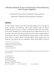
FIGURE 1:
TASK / PROCESS STATE TRANSITION DIAGRAM Executing State
(Context Switch)
ISR State (Waiting for Events)
Ready State
Waiting State
Data structures, displays, I/O hardware, and non-reentrant routines are a few resource examples. If two or more tasks use these resources, then they are called Shared Resources and you must protect them from being corrupted. They must have only one owner, a way of telling others to wait, and possibly a waiting list for future users of that resource. A rare example of a shared resource is when there exists a critical timing sequence of input and output operations to control some hardware. You must disable interrupts before starting this sequence, and re-enable them upon finishing. Note that Task #1 in the PIC16C64 example is an example of an “non-reentrant” routine that must be finished by the current owner before another task can use it.
Context Switch/Task Switch When one task takes over from another, the current values of the CPU registers for this running task are saved and the old saved registers for the new task are restored. The new task continues where it left off. This is all done by the Context Switch part of the Real-Time Kernel. Each task usually has a “context switch storage area”. Each task’s SP (Stack Pointer pointing into its own stack) is stored there along with all the other important saved registers. The “Remote Alarm” example does not need to use a context switch because all the important registers are properly freedup before each task is finished. The PIC16C64 example uses a similar concept, thus keeping the number of saved registers per task way down. We use an old concept called “where I came from”. The variable “FROM” is used to direct the dispatcher to start up the task where it left off. This is because you cannot manipulate the stack in the PIC16CXXX family. This same reason is why we have a “Semi-Preemptive” kernel on the PIC16C64 as an example. By the way, the faster the context switch is done, the better.
Scheduler The scheduler is that part of the kernel that decides which task will run next. We will talk about several common types in this section. This is where a lot of thinking should be done before starting your new project. By understanding the different kinds of schedulers and what features and problems each type has, you can match your problem to a creatively styled scheduler that meets your needs. For example, the PIC16C54 example shows the recalling of Tasks #1-3 just before a long sequence of code is executed. More creative ways can also be implemented, but be careful to allow all tasks to execute in a timely fashion. Please see Figure 1. Each task must be in “Ready State" or the "Executing State" to be considered by the scheduler to get temporary control of the CPU next.
(Events)
DS00585B-page 5-106
1997 Microchip Technology Inc.
AN585 Non-Preemptive Kernel
Preemptive vs. Non-Preemptive
The Non-Preemptive Kernel is also called a “Cooperative Kernel” because the tasks only give-up control when they want/need to in coordination with other tasks, and events. The “Remote Alarm” example uses a Non-Preemptive Kernel type, showing that despite its reputation as being a simple kernel type, a lot can be done with it. The Non-Preemptive Kernel type is well suited for the non-interrupt type PIC16C5Xs. The heart beat of the PIC16C54 example is the internal TMR0 counter crossing over from a high value to a low value of the counter. Use the prescaler to adjust the time units. The very fast tasks continually read the TMR0 directly comparing the delta of time to see if it should fire.
The Preemptive Kernel is harder to develop, but is easier to use, and is sometimes used incorrectly. You must spend more upfront time with the Non-Preemptive Kernel but it is better for more cramped microcontrollers. You get much better response time between a cause/ event and the response/action for that event with a Non-Preemptive Kernel. The Preemptive Kernel is more predictable in the response times, and can be calculated as to the maximum time to complete a given job. Often the Preemptive Kernel is more expensive.
Preemptive Kernel In a Preemptive Kernel, a running task can be swapped out for a higher priority task when it becomes ready. The Preemptive Kernel relies much more on interrupts as its driving force. The context switch is at the heart of this type of kernel. To implement a true Preemptive Kernel, you must be able to manipulate the stack. This is why we implemented a “Semi-Preemptive” kernel on the PIC16C64, with some of the best features of both types of kernels. We moved some of the tasks in the PIC16C54 example into ISRs to handle the I/Os. This works very well as the ISRs are very short and do most of the real work in this example. The TIMER0 interrupt is the heart beat for the PIC16C64 example. You must have a clock interrupt in order to make a true Preemptive kernel.
Round Robin Scheduler When the scheduler finds tasks on the ready queue that have the same priorities, the scheduler often uses a technique called Round Robin scheduling to make sure each task gets its day in the sun. This means more housekeeping to get it right. This is part of the creative ways you can tailor the scheduler to fit your needs. In the PIC16C54 example, all tasks will get to run shortly after their appointed time. This means that no task will dominate all others in this simple approach. In the “olden” days of the first Real-Time Operating Systems the term was used to mean the same as “time slicing”. The Preemptive Kernels of today are a major step forward, with their priority schemes, and intertask communication capabilities.
1997 Microchip Technology Inc.
Reentrancy In a Preemptive Kernel, two or more tasks may want to use the same subroutine. The problem is that you can not control when a task is swapped out and when another takes its place. Thus, if a subroutine uses only local or passed variables that are stored only in each tasks’ stack, then it is call reentrant or a pure routine. No global variables or hardware may be used in such a pure routine. A way around this reentrancy requirement is to treat the whole subroutine as a critical section. Appendix D is an example of reentrant code segment as might have been used in the PIC16C54 code example.
Task Priority Some tasks are not created equal. Some jobs must be done on time or data will be lost. Make the tasks that must get done the highest priority and go down the scale from there. Some kernels make you have a different priority for each task. This is a good idea and requires some thought before coding to make the design work.
Static vs. Dynamic Priorities and Priority Inversions For most embedded Real-Time Kernels, both static priorities and static tasks are used. Dynamic priorities are sometimes used to solve deadlock and other complex situations that arise from not understanding the problem and not understanding Real-Time Techniques. If the need for dynamic priorities seem to occur, you should relook at how you divided the problem, and divide less so as to include the resources in question under one semaphore. You could divide the problem more to have more tasks not needing two or more resources to complete its job, and have the new tasks talk more together.
DS00585B-page 5-107
AN585 As for Dynamic tasks, you should define the problem so as to know, ahead of coding, the continuous use of all tasks. You will need more upfront time in the planning stage to get all tasks talking, but it is well worth it to keep Dynamic Priorities and Dynamic Tasking out of the kernel design. Priority Inversions is a trick used to get past a poorly designed system by inverting the priorities to allow lower tasks to run that were previously blocked. This is a cheap trick, and is best kept out of a Real-Time Kernel. Use the other techniques outlined in this section to solve this kind of problem.
Semaphores There are basically two types: binary and counting semaphores. The binary semaphore allows only one owner, and all other tasks wanting access are made to wait. The counting semaphore keeps a list of users that need access. Semaphores can be used in many ways. We will illustrate most of them in the following paragraphs. Note that you can implement counting semaphores using binary semaphores.
Synchronization Semaphores can be used to synchronize tasks so that messages can be passed between them. Also tasks can be started up by semaphores, stopped by semaphores, or started together. They are the foundation blocks for Real-Time Programming. Once you have built a binary semaphore for your kernel, you can build very complex semaphores to synchronize anything. In the PIC16C54 example, data from several sources are passed out the Serial Port Resource. Task #4 synchronizes the other tasks trying to send data out and synchronizes with task #1 to get it done. When task #1 is running, then task #4 can not run until task #1 is ready for more data to send out.
Intertask Communication We have touched on this topic already, but for large kernels, one can include more complex communication methods to pass data/messages between tasks. Much of the handshaking is done for you inside the kernel. This takes a lot more space and execution speed to implement them in a kernel.
Mutual Exclusion
Event Flags
We have touched on the subject of Mutual Exclusion earlier (a method to exclude other tasks from gaining access to critical sections). Mutual Exclusion is the process of excluding others from access to the shared resources. To make a semaphore is a very complicated process. The semaphore’s construction must be atomic. That means that once the process has started, it can not be interrupted until it has saved the name of the new owner. From there on, it knows that no one else can break-in and change owners. We have implemented a binary semaphore using bits and kernel functions to mutually exclude access in the PIC16C54 example.
We implemented Event Flags as simple bits having two states (on and off). More info can be stored per Event Flag such as time it was recorded, by who, and who the event belongs to, and whether data was lost.
In the PIC16C64 example, we also disable interrupts to get the same effect. There are at least two good ways of implementing a binary semaphore. The first and oldest way was discovered by a Dutch mathematician named Dekker. We will refer you to a book that talks more about this algorithm. The second method of implementing a binary semaphore was also discovered by another Dutchman named Dijkstra. This method uses the “testandset” type instruction and is much more important to us. We used the dec & jump if not zero instruction (see PIC16C64 example).
This again is a very nice feature if you have the execution time, and the ram to implement them. This feature is related to Mailboxes, in that you can store several messages even after reading, to be processed later. If you want to only operate on the highest prioritized messages before handling the rest, this is allowed. You can be very fancy with the Mailboxes and Queues. If you have them, use them.
Message Mailboxes This is a nice feature to have if you have the ram space. Mailboxes allow the designer to pass messages between tasks, and allows messages to be looked at when the task is ready, and to reply telling the sender that the message was received. One message can be sent to many tasks at the same time.
Message Queues
Deadlock Deadlock is a condition where two or more tasks own resources that other tasks need to complete there assignment but will not release their own resources until the other tasks release theirs. Talk about cooperation. Please read section, "Static vs. Dynamic Priorities and Priority Inversions" for a discussion about such problems and ways to solve them. The root of such problems is not understanding the original problem.
DS00585B-page 5-108
1997 Microchip Technology Inc.
AN585 Interrupts
ISR Processing Time
Interrupts are one of the best inventions to come along for solving Real-Time problems. You can get very quick response to the need, and then go back to what you were doing. The only problem is that they can and do happen at the worst times. That means that you must learn how to turn them on and off to protect your critical sections. Note that before an interrupt can be handled, you must save all important registers so that you can restore them so that the kernel can restart the task where it left off. This is much like the context switch issue, but for interrupts, you must always save and restore. In the PIC16C64 example, the Status, W, and FSR registers are saved in RAM because of the interrupt. The PC register is saved onto the stack by hardware.
ISR (Interrupt Service Routine) Processing Time is defined as the time an ISR keeps control of the CPU. This amount of time should be short, and if a lot of processing needs to be done in a ISR, then break up the ISR. The new ISR should now just store the new data and return. Next, create a new task and move the extra code from the old ISR into the new task. Remember that the longer you are in one interrupt, the longer you can not answer another pressing interrupt.
Interrupt Latency, Response and Recovery Interrupt Latency is defined as the largest time period that interrupts are disabled, plus the time it takes for the ISR to start to execute. The Interrupt Response Time is defined for a NonPreemptive system as Interrupt Latency plus the “context saving time.” For a Preemptive system, add the execution time for the kernel to record the interrupt. Interrupt Recovery Time for a Non-Preemptive system is defined as the time to restore the saved context and for the restarting of the task that was interrupted. Interrupt Recovery Time for a Preemptive system is the same as for the Non-Preemptive system plus the time the kernel takes in the scheduler deciding which task to run next. These measurements are how most kernels are compared with each other. The PIC16C64 example does very well in these measurements. That is because of the PIC16CXXX processor and that they are mostly a Non-Preemptive system. You must keep the time you disable interrupts to a minimum in any kernel you write or any task that you write. You should break-up long sequences of instructions to allow for interrupts that are already waiting to execute.
1997 Microchip Technology Inc.
Nesting interrupts are where the interrupt with a higher priority can interrupt a lower priority interrupt. Care must be used, as different interrupts may have critical sections too, and disabling interrupts must be used here too to protect critical sections. Nesting of interrupts may not exist on all microcontrollers, such as the PIC16CXXX family.
Non-Maskable Interrupts On some microprocessors, you can enable/disable selected interrupts, such as on the PICmicro family. This is a great tool to control the flow of data into the system and out. Some systems have what is called Non-Maskable Interrupts. Here you can not turn them off by software masking. These NMIs as they are call for short, are used as clock Ticks, because you do not want problems with complex critical sections on a interrupt that you can not turn off. The PIC16CXXX family does not have any NMIs. NMIs are not as useful as maskable interrupts.
Clock Tick The Clock Tick, is the heart beat of the system. This is how the kernel keeps time (relative & absolute). This is how the kernel is restarted to see if there is a delay that has finished, so that the task can be moved into the ready state. In the PIC16C54 example, the Timer0 clock is used. In the PIC16C64 example, Timer0 is used. You must have a clock interrupt in order to make a true Preemptive kernel. This is the other reason why we implemented a Non-Preemptive Kernel on the PIC16C54 - no clock interrupt.
DS00585B-page 5-109
AN585 ANALYSIS OF CODE EXAMPLES These sections are the real meat of this article. In these sections we will explain how the concepts are put to practical use line by line in each of the two main examples - PIC16C54 (Appendix C) and PIC16C64 (Appendix D). We will also examine a short reentrant code example in Appendix B. We will give some ideas on how to expand the examples and how far and how fast the examples can be pushed. Be sure to read both sections on the two examples. The “Remote Alarm” application has many interesting features. The concept is to have as many tiers of units like a tree feeding into the lower level units the status of each of the larger branches to one central point. Each unit can detect any changes in status before the intruder shuts that unit down, or tampers with it. If any unit’s power or wires connecting it down the tree are cut, the lack of the flow of status and passwords would be noticed in five seconds and reported down the line. The two Serial Input lines per unit receive the status and passwords from it’s two larger branches, checking the data and passing the info down the line by its own Serial Output line. The seven input status lines are debounced in these examples, showing the technique. The LED on each unit reports the status at that node as to the importance of its own seven input status lines and the status flowing down the line. The level indication outputted on the LED continues at the last highest level until either a reset is received on the “Reset State” line or five minutes of no new activity on the seven input status lines are received. When either of these two events occur, the level of the LED output is adjusted to the current level of input. Some of the features are changed for this article (Figure 2 and Figure 5). Another Embedded System use of this type of “Remote Alarm” application is that of placing the unit on the outside of a safe. Hopefully the intruder would be detected before arriving at the unit itself. The continuous stream of status and passwords to the larger unit inside would slow down any simple theft.
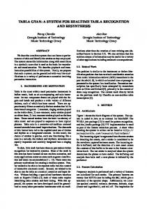
PIC16C54 - “Remote Alarm” Example This example is a cross between a true application and an attempt to show new concepts and some extra features for show. Some of the application specific code has been removed to show more clearly the possibilities of a Real-time Operating System on the PICmicro family. We chose the Baud rate for the Serial output to be twice the speed of the two Serial inputs because it is harder to accurately output a precise Serial Output than it is to monitor Serial inputs.
DS00585B-page 5-110
FIGURE 2:
REMOTE ALARM-PIC16C54 EXAMPLE
Serial IN 1
LED Level PIC16C54
Serial IN 2
Serial OUT Remote Alarm
7 Sensors IN
Reset State
This example operates at 4 Mhz. By simply increasing the crystal speed to 8 MHz, the two Asynchronous input Serial Baud rates increase from 4800 Baud to 9600 Baud. The Serial Output Baud rate increases from 9600 Baud to 19,200 Baud. By increasing the crystal speed to 16 MHz, it will increase the Baud rates to 19,200 Baud for the two independent Asynchronous inputs, and increase the baud rate for the Asynchronous Serial output to 38,400 Baud. By adjusting the constants in the code for the Serial routines, other Baud rates can be achieved at other crystal speeds. Note that you must use a very stable crystal setup and NOT an RC combination to run these examples. We will now give a quick outline of the PIC16C54 code example. Lines 1-85 are the equates for this program. Lines 88-95 are simple jump tables so as to save some of the precious “first 256 bytes” of each page. The Serial Output Routines - Task #1 are in lines 97-159. Task #7’s subroutines start at line 160 and continue to line 277. In this section, the LED output is controlled. The subroutine QCheck_T123, lines 278-301, is used to allow the checking of Tasks #1-3 to see if they are ready to execute before a long section of code in a slower Task is about to be executed. This is a creative way for the Kernel’s Scheduler to makes sure that the highest Prioritized Tasks get serviced before the less important tasks get executed. Task #2 starts at line 302. This task reads the Serial Input #1 for Asynchronous data. Task #2 can be described as a State Machine for outputting a byte Serially. Task #3 interrupts the code of Task #2 at line 333 and continues until line 362. Task #3 also reads the Serial Input but on input #2. Task #2’s subroutines continue at line 363 and continue until line 423. Task #3’s subroutines continue at line 424 and continue until line 484 is reached. The main or starting code is started at line 485. From that line to line 515, all variables are initialized, and all tasks are initialized at this time also. The Main Loop is started at line 516 and ends at line 665. This is where the real action is done. Each task checks the time to see if the conditions are correct for it to run. The tasks that are not Blocked, and have a job to do now are in a Ready State. In the Main Loop, we check the current state of
1997 Microchip Technology Inc.
AN585 each task in order of Priority (1-9). If ready, we do a very simple Task Switch and place that task in the Executing State/Running State. Several time unit changes take place in the Main Loop. Tasks #1-4 use 2 µs as a time base by reading the TMR0 directly. A time unit change takes place at lines 562-575 to 512 µs per unit for Tasks #5-6. Another time unit change takes place for Tasks #7-9, to 131072 µs per unit. For Tasks #5-9, each task counts the time units and compares them to their standard for activation or activity. Task #4 starts at line 538 and finishes at line 561. Task #4 controls the feeding of Task #1 from several other tasks that want data to be outputted. It uses several Semaphores to make sure that Task #1 is not bothered until it is ready for another byte. Task #5 monitors the Level Reset Line, and is always running. It simply resets the status of the LED, to be recalculated in Task #6. Task #5 runs through lines 576-581, and is very short. Lines 582-611 represent Task #6. Here we debounce the seven sensor input lines, leaving the current standard in the variable “Old_RB”. Task #6 asks/Signals Task #4 to output the current standard out the Serial pin. Task #7’s main code is lines 621-628. Task #8 is a five second lack of activity timer, and exists in lines 629-645. If no data comes from either of the two input Serial lines, then Task #8 Signals Task #4 to send a special byte to be outputted by Task #1. This Signals the next “Remote Alarm” of the lack of communication between units. The last task is Task #9. This is a five minute lack of Severe Errors the from Sensor Reset Timer. Lines 646663 compose Task #9. Subroutine Do_D_H_E_L starts at line 667 and continues through to line 692. This routine determines the Highest Error Level, and passes Task #7, the current state, to output on the LED. Lines 693-703, clear the registers #7-1Fh. The “jump at Power-On” code is the last lines 705-706. The following sections describe in more detail how and what each part of the code does and why. The code segment lines 1-87 are explained in this paragraph. Line 4 tells the MPASM assembler which PICmicro you are using. The include file PICREG.H follows with the equates and assignments to make the code more readable and changeable. You should use equates that relate symbols to each other. The Constants lines 10-12 are the values to change for different Baud rates. They represent the Bit Times for the Baud rates divided by 2 minus some latency factor. You might have to adjust the “Fudge Factor” and other values to fine tune the performance. The value used for the “Fudge Factor” is related to the longest path of code. Lines 2124 are an experiment that allows a simple name to be associated to a single bit. This allows for easily changeable assignments. Lines 30-54 are the variable assignments. Variables (lines 35-39) are used as time counters. They count the number of units of time, and are compared to literals to see if an Event has just happened. The bits defined in lines 57-64 are used as Binary Semaphores. They keep Critical Sections of data protected. We will see them in action later in the code. The bits defined in lines 67-73 are error flags.
1997 Microchip Technology Inc.
They define the current or last error states of the Serial routines, and whether data was lost coming in or out. The section of equates in lines 76-85 are used to define the different LED activity. They are used by Task #7 to keep the LED blinking. In lines 89-94, we try to save the all important first 256 bytes of any page. Task #1 outputs a byte Asynchronously over the Serial Output pin. Task #1 is started at line 98. The time units used for Tasks #1-4 are 2µS. We first sample the TMR0 and store the count. When Tasks #1-4 are then allowed to run, they check the difference between the first sample and the current time. If the delta is greater than or equal to the delay, then that Event has just happened. We first check if the state of the Serial Output is zero. We then jump to OStateS to start the outputting of the “Start Bit”. Because any Serial Output timings must be rock solid, we use a trick in lines 101116 that helps greatly. We check if we are within a certain amount of time BEFORE the deadline and then wait for the time to output another bit. This trick allows us to be within a certain ± amount of time within the expected time to output that bit. With this code, we are about