for more accurate processing and routing of packets using any fields that ... tern matcher, a parsing structure, and a routing module. Both the pattern .... ple business card. It contains fields for a ..... chine via the small test application shown in figure 12. The ... the Sixth European Software Engineering Conference (ESEC/FSE.
A RECONFIGURABLE ARCHITECTURE FOR MULTI-GIGABIT SPEED CONTENT-BASED ROUTING James Moscola, Young H. Cho, John W. Lockwood ∗ Dept. of Computer Science and Engineering Washington University, St. Louis, MO {jmm5, young, lockwood}@arl.wustl.edu
ABSTRACT This paper presents a reconfigurable architecture for highspeed content-based routing. Our architecture goes beyond simple pattern matching by implementing a parsing engine that defines the semantics of patterns that are parsed within the data stream. Defining the semantics of patterns allows for more accurate processing and routing of packets using any fields that appear within the payload of the packet. The architecture consists of several components, including a pattern matcher, a parsing structure, and a routing module. Both the pattern matcher and parsing structure are automatically generated using an application-specific compiler that is described in this paper. The compiler accepts a grammar specification as input and outputs a data parser in VHDL. The routing module receives control signals from both the pattern matcher and the parsing structure that aid in the routing of packets. We illustrate how a content-based router can be implemented with our technique using an XML parser as an example. The XML parser presented was designed, implemented, and tested in a Xilinx Virtex XCV2000E FPGA on the FPX platform. It is capable of processing 32-bits of data per clock cycle and runs at 100 MHz. This allows the system to process and route XML messages at 3.2 Gbps.
1. INTRODUCTION Typical routers use layers 1 through 4 to route network packets. On the Internet, IP addresses are commonly used to route packets. However, such routing schemes require packet senders to obtain the destination address before sending the packets. Such interaction introduces overhead at the application level and places constraints on the scalability and dynamics of the network. ∗ This research was sponsored by the Air Force Research Laboratory, Air Force Materiel Command, USAF, under Contract number MDA97203-9-0001. The views and conclusions contained herein are those of the authors and should not be interpreted as necessarily representing the official policies or endorsements, either expressed or implied, of AFRL or the U.S. Government.
As the Internet continues to expand, researchers are starting to look at content-based routing as a mechanism to improve upon and/or add new services for managing the distribution of data. Content-based routing improves upon the existing Internet model by giving users the freedom to describe routing schemes in the application layer of the network packets. Content-based routers then inspect and interpret packet payloads and route packets according to the content of the packet. One example of this type of interaction can be seen in publish/subscribe networks [1, 2]. Users can subscribe to information that is interesting to them by sending high level descriptions to routers using the application layer (layer 7) of the packet. Content-based routers then interpret the subscription packet content and route all messages with matching contents to the subscriber. Some examples for publish/subscribe networks include the routing of stock quotes, distribution of weather reports, and streaming video broadcasts. Content-based routing can also be used for applications such as load balancing in web server clusters [3], or routing of online transactions to the appropriate shipping warehouse. It is this class of content-based routing applications that is the focus of this paper. To route packets based on values that appear in the payload, efficient methods for packet payload processing are needed. Carzaniga, Rutherford, and Wolf presented a software based routing algorithm in [4]. However, due to the processing power required by deep content inspection, software approaches are unlikely to maintain the throughput of multi-gigabit networks. This can potentially limit the adoption of content-based networks. As such we propose a reconfigurable hardware architecture capable of intelligent content inspection. In this paper we describe the implementation of a contentbased routing architecture that has been implemented in reconfigurable hardware. Our system performs much more than simple pattern matching – the architecture takes the next evolutionary step in message content processing by implementing a complete parser. Given a grammar specification, our parser architecture is capable of understanding the
semantics of and routing any message format. Our architecture has been fully implemented on the Field-Programmable Port Extender (FPX) platform which allows for rapid deployment and testing in gigabit-rate networks. The remainder of this paper is divided into the following sections. Section 2 gives a brief description of the implementation platform and supporting work. Section 3 describes our approach and architecture for content-based routing. Performance and area numbers are presented in section 4. Section 5 presents concluding statements.
Data Packets
Content-Based Router
Data Packets
IP Processor Frame Processor Cell Processor
Fig. 1. Content-based router in protocol wrappers
2. BACKGROUND
3. CONTENT-BASED ROUTER ARCHITECTURE
The hardware platform and modules used to implement parts of our content-based router have been described in previous papers. This section includes a short description of that work, including the FPX platform and a set protocol wrappers.
Our architecture for content-based routing can route packets with many different formats. Instead of routing packets based on strings that appear within the packet, our architecture achieves a higher level of understanding of each packet by fully parsing the entire payload. Packet formats to be routed are specified using grammars. In this paper we illustrate how our architecture is configured and used to route XML packets. Since its introduction, XML has become the format of choice for exchanging information over networks. Additionally, we choose XML because there are many grammars already available for XML messages in the form of document type definitions (DTD).
2.1. Field-Programmable Port Extender The FPX is a general purpose, reprogrammable platform that performs data processing in FPGA hardware [5, 6]. As data packets pass through the device, they can be processed in the hardware by user-defined, reprogrammable modules. Hardware-accelerated data processing enables the FPX to process data at multi-gigabit per second rates, even when performing deep processing of packet payloads. Version 2 of the FPX contains two FPGAs. A Xilinx Virtex XCV600E FPGA called the Network Interface Device (NID) routes packets into and out of the FPX. It also controls the routing of packets to and from the application FPGA. The Reconfigurable Application Device (RAD) is another FPGA, which is configured over the network to perform the customized data processing functions. The RAD is implemented with a large Xilinx Virtex XCV2000E. The FPX also contains two banks of 36-bit wide Zero-Bus-Turnaround Static RAM (ZBT SRAM) and two banks of 64-bit PC-100 Synchronous Dynamic RAM (SDRAM) which provided ample space for off-chip data storage.. 2.2. Protocol Wrappers To provide a higher level of abstraction for packet processing, a library of layered protocol wrappers was implemented for the FPX [7]. They use a layered design and consist of different processing circuits within each layer. At the lowest level, a cell processor processes raw cells between network interfaces. At the higher levels, a frame processor reassembles and processes variable length frames while an IP processor processes IP packets. Figure 1 shows the configuration of our content-based router in the protocol wrappers.
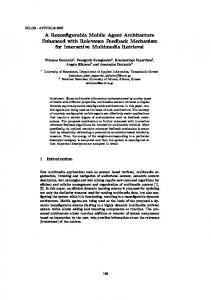
card routekey name first last title phone
(routekey, name, title?, phone?)> (#PCDATA)> ((first, last) | (last, first))> (#PCDATA)> (#PCDATA)> (#PCDATA)> (#PCDATA)>
Fig. 2. DTD for example implementation
STRING [a-zA-Z0-9-]+ %% card: "" routekey name title phone "" routekey: "" route "" route: routefirst | routelast routefirst: "first" routelast: "last" name: "" nameN "" nameN: nameFL | nameLF nameFL: firstFL lastFL nameLF: lastLF firstLF firstFL: "" STRING "" lastFL: "" STRING "" lastLF: "" STRING "" firstLF: "" STRING "" title: "" STRING "" | ε phone: "" STRING "" | ε %%
Fig. 3. Lex/Yacc style grammar for example implementation Figure 2 shows an example DTD which represents a simple business card. It contains fields for a first name, a last name, a title, and a phone number. Additionally, the DTD
Routing Module
data packets
Fig. 4. Content-based router architecture
3.1. Pattern Matcher Data packets enter our content-based router via the layered protocol wrappers. The first stage in processing each packet for routing is pattern matching. Our modular design, allows a variety of techniques to be used for pattern matching. For this implementation, we use a modified decoded character pipeline [8, 9] which has been scaled to accept a four character wide (32-bit) input. Scaling is achieved by replicating the pipeline until there is one pipeline for each character in the input width. A detailed block diagram of the decoded character pipeline is shown in figure 5. The scaled pipeline receives four characters (32-bits) per clock cycle from the layered protocol wrappers. Characters 1, 2, 3, and 4 are passed into pipeline alignments 3, 2, 1, and 0 respectively. Before entering the pipeline registers, characters are passed into an 8-to-256-bit decoder. The 256-bit output represents a single bit line for each of the 256 possible ASCII characters. This decreases the routing resource required for string detectors. The decoded character lines
m4
... m0 ... m1 ... m2 ... m3 ...
Alignment 3 [23:16] Alignment 2 [15:8] Alignment 1 [7:0]
Pattern Matcher
Alignment 0
Fig. 5. Detailed view of the pattern matcher pipeline
are passed into the pipeline registers as illustrated in figure 5. The pipeline can detect patterns that are less than or equal to the length of the pipeline. Additionally, the pipeline only needs to be as long as the longest pattern in the grammar The actual pattern matching is executed by a series of string detectors. A string detector is generated for each of the patterns in the input grammar. For our example grammar in figure 3 there are 17 unique patterns: , , , , first, last, , , , , , , , , , , and STRING. Each of these patterns can be detected by ANDing together the appropriate bits from the decoded character pipeline. Since we are using a scaled pipeline, we need to check for the presence of a pattern at each possible starting alignment. A pattern is detected if it is found at any one of the four possible starting alignments. Figure 6 illustrates the logic required to match the patten . The notation shown in figure 6 is Register[Alignment][Character]. For example, m1[0][c] represents the ‘c’ character bit of register m1 in alignment 0. A single bit line is output from the pattern matcher to the parser structure for each of the string detectors.
pattern(0) ""
pattern(1)
String Detectors
...
Token FIFO
Parsing Structure
8-bit to 256-bit decoder
m2[0][]
32
Pattern Matcher
[32:24]
...
data packets
...
32
a b c
m1[3][]
...
data
m1[2][]
Grammar
256-bit decoded registers
...
Patterns
One copy for each alignment
m1[1][]
contains a routekey field which indicates which field the router should use for routing. We will use this DTD throughout the remainder of the paper to illustrate our content-based router architecture. Prior to generating the hardware to parse the DTD in figure 2, we first convert the DTD into a Lex/Yacc style grammar. The Lex/Yacc style grammar is shown in figure 3. This grammar is then passed into a custom compiler which automatically generates the VHDL required for the dynamic components of the architecture. The dynamic components include a pattern matcher and a parsing structure. These components have a static interface which allows them to integrate easily with the static components of the architecture. The layout of the main components of our architecture, including the pattern matcher, the parsing structure, and the routing module, is shown in figure 4. The remainder of this section will describe each of these components in more detail.
pattern(n)
Fig. 6. Detailed view of a string detector
3.2. Parsing Structure The parsing structure gives the content-based router a higher level of understanding than just simple pattern matching. It defines the semantics of patterns as they are detected by the pattern matcher. The hardware logic for the parsing structure is determined from the input grammar (or grammars). The production list of a grammar defines all of the possible transitions for a grammar. While processing data, the parser maintains the state of the grammar allowing it to determine which patterns can occur next. For each terminal symbol Z FIRST [ Z ] ← {Z } repeat For each production X → Y1 ... Yk
routed to the input of other pattern registers. Transitions are determined from the production list of the grammar using the well known FIRST and FOLLOW set algorithms (figure 7) [10]. The FIRST algorithm is used to determine the starting point of the grammar. The FOLLOW set algorithm traverses through the production list to find sets of patterns that can follow any other patten in the grammar. The resulting sets are then used to map the output of pattern primitives to the input of each of the pattern primitives listed in its FOLLOW set. When there is more than one connection to the input of a pattern primitive, an OR gate is used to combine the signals into a single bit input. Figure 8 shows the FOLLOW sets for each of the patterns in our example grammar in 3. The resulting parsing structure for our example implementation is illustrated in figure 9.
if Y1 ... Yk are all nullable (or if k=0) then nullable[ X ] ← true
start of packet
For each i from 1 to k , each j from i+1 to k if Y1 ... Yi −1 are all nullable (or if i=1)
P6
P0
1
P12
2
P18
then FIRST [ X ] ← FIRST [ X ] ∪ FIRST [Yi ] if Yi +1 ... Yk are all nullable (or if i=k )
P1
P7
STRING1
P13
STRING 2
P19
P22
then FOLLOW [Yi ] ← FOLLOW [Yi ] ∪ FOLLOW [ X ] if Yi +1 ... Y j −1 are all nullable (or if i+1=j ) then FOLLOW [Yi ] ← FOLLOW [Yi ] ∪ FOLLOW [Y j ]
P2
P3
first
last
P8
1
P20
P14
2
P23
STRING
STRING
until FIRST , FOLLOW and nullable no longer change P9
1
Fig. 7. FIRST and FOLLOW set algorithms
Non-terminals
FOLLOW Set
first, last
first, last
1, 1
1, 1, 2, 2, ,
STRING
STIRNG
1, 1, 2, 2, ,
1
1
2
2
1, 2
, ,
,
Fig. 8. FOLLOW sets for example implementation In our parsing structure, each pattern is represented using a simple primitive that consists of a single register and a single AND gate. The inputs to each of the AND gates are the outputs of the pattern matcher. The output of each AND gate represents a transition in the state of the grammar and is
P4
P10
STRING1
P5
P24
P16
STRING 2
P11
1
P21
P15
2
P17
2
P25
Parsing Structure
XML valid
Fig. 9. Detailed view of the parsing structure
The generated parsing structure processes packets one pattern at a time. At the start of a packet, the starting register (register P0 in figure 9) is set. As packets are processed, the parsing structure receives a signal from the pattern matcher for each pattern that is found. These signals allow the parsing structure to traverse through the grammar and maintain the semantics of the data stream. During processing, all signals from the pattern matcher are sent downstream to the routing module accompanied by the state of the parsing structure. The state of the parsing structure indicates where in the grammar each pattern is found. Knowing where in the grammar a pattern is found allows the routing module to make more intelligent decisions.
3.2.1. Validating XML Input To avoid routing invalid or malformed XML messages, our content-based router validates all XML messages prior to routing them. As shown in figure 9, an XML valid signal is asserted when the parsing structure successfully traverses through the entire grammar. The XML valid signal is forwarded to the routing module. 3.3. Routing Module The routing module (figure 10) is responsible for modifying the IP header of each packet to route the packet to the appropriate destination. As packets enter the content-based router they are buffered in the routing module until the packet has been completely processed. Prior to routing any packet, the routing module verifies that the packet is the correct format. Most importantly, this entails validating the XML message. XML messages that do not strictly adhere to the grammar provided will not be rerouted by the module. Optionally, the module can also check for specific IP address and port ranges prior to routing. data packets
output controller
32
data packets
Packet Buffer IP valid Port valid XML valid
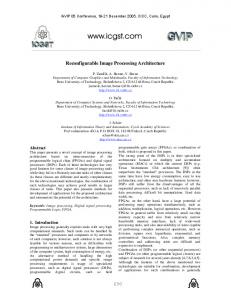
name in the XML message. These values stay enabled for the duration of the packet. The firstSTRING value is enabled by the parsing structure when either register P7 or register P16 are set and a STRING pattern is detected by the pattern matcher. Similarly, the lastSTRING value is enabled when either register P10 or P13 are set and a STRING pattern is detected. The firstSTRING and lastSTRING values are only valid for a single clock cycle. During this clock cycle, the first character of the STRING pattern (the route character) is forwarded to the routing module and stored. This value is then used to address a routing table which determines the next destination of the packet being processed. Once a packet has been fully processed, the output controller reads the packet from the packet buffer for output. If the packet contains a valid XML message (and optionally, IP address and port ranges), then the IP header is rewritten with the new destination address as it is output. 4. IMPLEMENTATION The content-based router described in this paper was fully implemented and tested on the Xilinx Virtex XCV2000E FPGA on the FPX platform. The FPX was integrated into a Global Velocity GVS-1000 chassis. A photograph of an FPX and the GVS-1000 chassis is shown in figure 11.
reroute packet
routefirst firstSTRING routelast lastSTRING route character
8
Routing Module
D E Q
dest. IP
route data Route Table
Fig. 11. FPX and GVS-1000 chassis Fig. 10. Detailed view of the routing module For our example implementation, we want to route packets based on the first character of either the first name or the last name specified in the XML message. The routekey value specifies which name to use for routing. A series of control signals received from the pattern matcher and the parsing module allow the routing module to route packets accordingly. These control signals are described below and can be seen in figure 10. The value routefirst is enabled by the parsing structure when register P2 is set and the pattern first is detected by the pattern matcher. This value indicates that the packet should be routed according to the first name in the XML message. Similarly, the value routelast is enabled when register P3 is set and the pattern last is detected. It indicates that the packet should be routed according to the last
The GVS-1000 has two bidirectional gigabit interfaces for passing traffic into the FPX. To test our content-based router architecture, each of the gigabit interfaces on the GVS1000 were connected to a different host machines. One machine was used to generate and send XML messages into the content-based router. The second machine was used as a receiver for routed messages. Since only two machines were used for our experiments, we routed XML messages to different ports on the receiving machine based on the message content. Both Ethereal and a small counter application were used to verify XML messages arrived at the correct destination port on the receiving machine. XML data messages were generated on the sending machine via the small test application shown in figure 12. The test application creates XML messages using the values specified in the text fields and sends them as UDP packets into
the content-based router. Additionally, the test application can randomly generate and send a specified number of XML messages into the content-based router. An example XML message is shown in figure 13.
Fig. 12. Test application interface
routing architecture means we can fit much larger and/or many more grammars on the FPGA. 5. CONCLUSION In this paper we presented a content-based router application that has been implemented with Field Programmable Gate Arrays. The content-based router consists of a pattern matcher, a parsing structure and a routing module. The pattern matcher and the parsing structure are automatically generated by a custom compiler that accepts grammars as input. The routing module receives control signals from the pattern matcher and the parsing structure that aid in the routing of the packet. The router is wrapped in a set of layered protocol wrappers that handle all the required protocol processing. The content-based router was implemented and tested in the Xilinx Virtex XCV2000E FPGA on the FPX platform. The architecture was placed and routed at 100 MHz and can process XML messages at 3.2 Gbps. Without the layered protocol wrappers, the content-based router architecture is capable of running at over 200 MHz and processing XML messages at over 6.4 Gbps. 6. REFERENCES
first John Doe Citizen 555-555-5555
Fig. 13. XML packet contents
4.1. Area and Performance For this application our maximum clock frequency is limited to 100 MHz by the layered protocol wrappers. At this speed our content-based router can achieve a maximum throughput of 3.2 Gbps. Without the protocol wrappers, the core of the content-based router architecture can achieve frequencies over 200 MHz. At this speed the content-based router can route XML data messages at over 6.4 Gbps. The content-based router requires 3751 slice flip flops, approximately 9% of the available flip flop resources. The architecture requires 3058 4-input LUTs, approximately 7% of the available LUT resources. The layered protocol wrappers alone require 2623 flip flops and 2196 4-input LUTs. This is approximately 6% and 5% of the available flip flop and LUT resources respectively. The core of the content-based router (without the protocol wrappers) requires approximately 1128 slice flip flops and 862 4-input LUTs. This is approximately 2.9% and 2.2% of the available flip flop and LUT resources respectively. Such a small space requirement for the core of the
[1] A. Carzaniga, D. S. Rosenblum, and A. L. Wolf, “Design and evaluation of a wide-area event notification service,” ACM Transactions on Computer Systems, vol. 19, no. 3, pp. 332–383, Aug. 2001. [2] D. S. Rosenblum and A. L. Wolf, “A design framework for internet-scale event observation and notification,” in Proceedings of the Sixth European Software Engineering Conference (ESEC/FSE 97), M. Jazayeri and H. Schauer, Eds. Springer–Verlag, 1997, pp. 344–360. [3] Chu-Sing Yang and Mon-Yen Luo, “Efficient Support for ContentBased Routing in Web Server Clusters,” in Proceedings of USENIX Symposium on Internet Technologies & Systems (USITS), Boulder, CO, Oct. 1999. [4] A. Carzaniga, M. J. Rutherford, and A. L. Wolf, “A routing scheme for content-based networking,” in Proceedings of IEEE INFOCOM 2004, Hong Kong, China, Mar. 2004. [5] J. W. Lockwood, “An open platform for development of network processing modules in reprogrammable hardware,” in IEC DesignCon’01, Santa Clara, CA, Jan. 2001, pp. WB–19. [6] “Field Programmable Port Extender Homepage,” Online: http://www.arl.wustl.edu/projects/fpx/reconfig.htm, Aug. 2000. [7] F. Braun, J. W. Lockwood, and M. Waldvogel, “Layered Protocol Wrappers for Internet Packet Processing in Reconfigurable Hardware,” IEEE Micro, vol. Volume 22, no. Number 3, pp. 66–74, Feb. 2002. [8] Z. K. Baker and V. K. Prasanna, “A Methodology for Synthesis of Efficient Intrusion Detection Systems on FPGAs,” in IEEE Symposium on Field-Programmable Custom Computing Machines. Napa Valley, CA: IEEE, April 2004. [9] R. Sidhu and V. K. Prasanna, “Fast Regular Expression Matching using FPGAs,” in IEEE Symposium on Field-Programmable Custom Computing Machines. Napa Valley, CA: IEEE, Apr. 2001. [10] A. Aho, R. Sethi, and J. Ullman, Compilers: Principles and Techniques and Tools. Addison-Wesley, 1986.