A RECONFIGURABLE VITERBI TRACEBACK FOR IMPLEMENATION ON TURBO DECODING ARRAY Imran Ahmed*†
Tughrul Arslan*†
School of Electronics and Engineering. University of Edinburgh, King’s Buildings Mayfield Road, Edinburgh, EH9 3JL, UK email:
[email protected]
Institute for System Level Integration, The Alba Campus, The Alba Centre, Livingston, Scotland, EH54 7EG, UK email:
[email protected]
*
†
ABSTRACT The trace back operation as used in Viterbi decoding is presented. The trace back is used for a new large constraint length, soft decision viterbi decoder designed to be implemented reusing components of turbo decoding array. The viterbi decoder can be reconfigured for standards such as CDMA2000, WCDMA (UMTS), ADSL, IEEE 802.11 and GSM. The proposed trace back operation supports all of these multiple standards. The viterbi decoding is made reconfigurable between different trellis types, constraint lengths and rates that can be reconfigured for the desired standard. The reconfigurable fabric is implemented as a subset of turbo decoder array on a 180 nm UMC process technology.
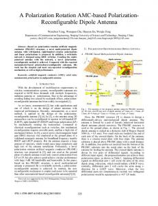
Size of PH RAM = (2L-1/2M) x WL x total windows ---- (1) --- where WL (window length) is 5-6 times the constraint length. ‘L’ is the constraint length and M=3 for 8 ACS units. The total processing of states (2L-1 states) is done by a smaller de Bruijin graph of 2M states. For example in equation (1), the size of the PH RAM for constraint length 9 (as in 3GPP) will be: Size of PH RAM =32x54x4 = 6912x8 bits. There is 8K (2Kx8) of output RAM available in turbo decoding array [4]. This is reused for PH Memory and is shown in the figure 1.
VLSI DESIGN The main aim of this reported research is to present the viterbi trace back operation used in an open trellis structure for a unified viterbi and turbo decoding for multiple standards. The viterbi components of the architecture can support up to 256 states, trellises with different generator polynomials and rates. In contrast to state serial [1,2] and fully parallel architectures [3] our viterbi design uses an intermediate solution. A better area and speed efficiency can be achieved by Processing N states (up to 256) by using P AddCompare-Select ‘ACS’ units (P=8) [3]. The survivor memories and their management with reconfigurable trace back approach are presented in the subsequent sections. 1.1. Path History (PH) Memory. Path History Memory is used in Viterbi algorithm to find the survivor path. The contents of this memory are updated on each stage ‘L’ of the trellis which allows reconstructing the survivor path. There are 8 ACS units in the array that output 8 decision bits per clock cycle. These decision bits (survivor states) are saved in the PH RAM. Total size of the PH RAM is given by:
0-7803-9782-7/06/$20.00 ©2006 IEEE
107
Figure 1. 2Kx4 identical path history RAMs, Segmentation and mappings shown for different standards. Each block of 2K RAM is used to store one window length (WL) of decision bits. These RAMs are segmented by total states of the trellis. For example, for 256 states there are 256 decision bits (one for each state). Therefore the RAMs will be divided into 32x8 wide segments. The total number of segments will be equal to one window length (constraint length x 6 = 54 for 3GPP). Figure 1 and table 1 show these mappings and segmentation for various standards. PH memory is read by trace back processors as they calculate the survivor path in the reverse traversing of the trellis. Memory utilization for Standard Const. length each 2K RAM=WL x segment size. W-CDMA(Japan) 9 54 x 32 =1728 X 8 bits CDMA 2000 UMTS GSM,PDC 5 30 x 2 = 60 X 8 bits IS-95, IEEE 802.16 7 42 x 8 = 336 X 8 bits
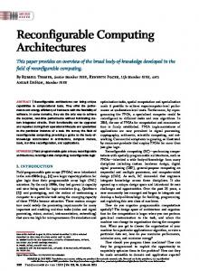
IS-54 6 36 x 4 = 144 X 8 bits Table1. Memory utilization for different standards. 1.2. Reconfigurable Trace Back Processing. The input/output state connections for the ACS blocks are explained in figure 2. Total number of states = 2 a+1.
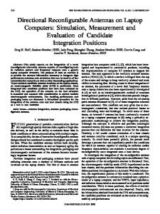
Figure 2. Next and Previous state calculation for all trellises For example if the state at stage ‘L’ of trellis is 0_1111111(figure 3); it implies that the decoded bit (shown in red) is 0 and the two possible states connected to this winning state at stage ‘L-1’ of trellis are 1111111_0 and 1111111_1. The previous winning state decisions are provided by PH RAMs. These were stored in PH RAMs during the ACS calculations.
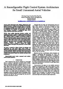
Let U4-U3_U2_U1_U0 are outputs of buffers B1B2_B3_B4 and C6_C5_C4_C3_C2_C1_C0 are the outputs of the 6 bit down counter. Output of the arithmetic shifter with zero shift is 0_0_0_0_C6_C5_C4_C3_C2_C1_C0. B1 B2 B3 B4 B5 B6 B7 B8 GSM On on on On On Off On On 3GPP Off Off off Off Off On Off Off Table 4. Tri state buffer controls for reconfigurable trace back processing The contents of the read register for 3GPP using the controls in table 4 and table 5 will be By a similar reasoning the read register contents for GSM are:
Figure 4. Traceback processing
Figure 3 Example showing previous state calculation There are two reverse processors B1 and B2 (dummy) working in parallel, each accessing separate PH RAM. B2 calculations initialize the start state of B1 To get the survivor path, we have chosen the trace back technique as register exchange in not preferred for large constraint lengths [5]. As explained above, the previous trellis path stage SL-1 is given by the current path state SL according to the following update. SL-1 = [SL