storage at a clock rate of 10 GHz, which is several times faster than the register files. This result shows that the superconducting delay-line memory is a powerful ...
A Reentrant Delay-line Memory Using a YBa2Cu3O7-d Coplanar Delay-line W. Hattori, T. Yoshitake, and S. Tahara Fundamental Research Labs., NEC Corp., 34 Miyukigaoka, Tsukuba 305-8501, Japan Abstract—The rapid growth in telecommunication traffic demands a higher-speed asynchronous transfer mode (ATM) switching system. At present, the upper limit of the system clock rate is determined by the maximum clock rate of conventional semiconductor memory devices, such as the register files used in ATM cell buffer storage. This is because the maximum clock rate of these register files is restricted by the propagation delay time between each register stage. Since a reentrant superconducting delay-line memory avoids this restriction using an analogue delay given by the superconducting delay line, we have proposed that this memory should be used in high-speed ATM cell buffer storage. Recently, we fabricated a 10-m mm-wide 37-cm-long YBa2Cu3O7-dd coplanar delay-line. This line had a delay of approximately 2.8 ns. Using this coplanar delay-line and an assembly of commercially available integrated circuits, we successfully developed a superconducting delay-line memory. This memory operates as a 32-bit buffer storage at a clock rate of 10 GHz, which is several times faster than the register files. This result shows that the superconducting delay-line memory is a powerful candidate for high-speed ATM cell buffer storage.
I. INTRODUCTION Asynchronous transfer mode (ATM) technology is a key technology for broadband integrated services digital networks. This is because ATM technology provides a universal interface and intelligent transfer services over high-speed digital communication networks, using self-routing fixed-length data packets called cells. Owing to the self-routing, unscheduled nature of cell arrival to an ATM switching system, two or more cells may simultaneously arrive as different inputs destined for the same output. To prevent cell collisions, the ATM switching system contains first-in first-out (FIFO) buffer memories such as register files for temporary cell storage. As the telecommunication traffic volume increases, aggregate throughput of over 1 Tbit/s will be required of the ATM switching system [1], [2]. To realize this large capacity with an acceptable quantity of hardware and a practical number of internal links and input/output ports, the ATM switching system will have to operate at a clock rate above 10 GHz if relying on conventional (~16x) parallelization [2]. Thus, it is necessary to develop high-performance interconnection, high-speed cross-connect switching LSIs, and highspeed low-latency buffer memories. There has been significant progress made in high-performance interconnection technology, especially related to high-temperature superconducting transmission lines [3]-[6]. High-speed cross-connect switching LSIs operating with a clock rate of 10 GHz have already been reported [7], [8]. Thus, if buffer memories that can be accompanied with these highspeed LSIs are developed, it will be possible to build a highthroughput ATM switching system with an aggregate throughput of
Manuscript received September 15, 1998.
over 1 Tbit/s. Unlike switching LSIs, however, such high-speed buffer memories are difficult to develop using conventional semiconductor memory devices. To date, although a register file is the fastest device in conventional semiconductor memory devices, the maximum clock rate is no more than 3 GHz and this device limits the operating speed of the ATM switching system [9], [10]. Thus, there is a speed gap between the memory devices and the cross-connect switching LSIs. To get rid of this speed gap, we have proposed using reentrant superconducting delay-line memories as an ATM cell buffer storage. Recently, we successfully developed and demonstrated a reentrant superconducting delay-line memory using a YBa2Cu3O7-d (YBCO) coplanar delay-line. In this paper, we describe the circuit configuration and the operating principles of this memory. We also discuss the experimental results from our evaluation of this memory. II. CIRCUIT CONFIGURATION AND OPERATING PRINCIPLES The configuration of the superconducting reentrant delay-line memory is illustrated in Figure 1(a). The proposed memory has recirculation loop storage for a fixed-length data packet, similarly to an optical-fiber delay-line memory [11], [12]. This memory consists of a superconducting delay-line and a 2 x 2-crossbar switch. This delay line gives input-data a fixed-delay, which corresponds to its line-length. The crossbar switch enables cross or parallel connection between two input-ports and two output-ports. The delay line feeds back from a output port of the switch to its input port and forms a storage loop. This loop has a duration that corresponds to a fixed data packet length. Without considering redundant bits or guard time temporarily added in the switch, the packet length become 27 bits in the case of 16 parallelization, owing to the standard ATM cell length of 424 bits [2]. This packet circulates in the loop and the 2 x 2-crossbar switch controls the insertion (extraction) of the packet into (from) the recirculation loop storage. That is, this memory operates as a FIFO buffer memory. To prevent timing jitter, attenuation and distortion from accumulating during each round trip, the switch has single register stage, as shown in Fig. 1(b). This register stage retimes the data, and also amplifies and reshapes the signal waveform. Since signals in the delay line cannot be amplified and reshaped, the delay line must have extremely low attenuation and distortion despite the high clock rate and long delay. This is impossible using a planar transmission line made of normal metal, owing to their extremely high surface resistance in comparison with that of a superconductor. This is why we used the superconducting delay-line. Furthermore, the delay time given by the loop must be accurately designed to agree with the packet length within the tolerance for synchronization in the register stage. That is, the arrival timing of a data pulse at the input port of the switch, which is returned through the delay line, must be within this tolerance from the clock edge. The pulse is then
Superconducting Delay Line
Register Stage
Delay Line
Input Data (D in) Storage Loop Select Data (S) Clock (clk) DIn
Q0 Q0
Din
Q
clk
Q
DIn
Q
clk
Q
DIn
Q
clk
Q
Selector Stage D0 D1 S
Q
D0 D1 S
Q
Delay Line
Q
Q
Output Data (DOut)
Q1 Q1
2x2-C rossbar Switch
Clock Distributor
(a)
(b)
Fig. 1. (a) Configuration of the reentrant superconducting delay-line memory. This memory consists of a superconducting delay-line and a 2 x 2-crossbar switch. The solid arrows show the crossbar switch in the bar state (=), and the dashed allows show the cross state (X). (b) Block diagram of the 2 x 2-crossbar switch. Each square enclosed by a solid line means a bare chip The crossbar switch consists of a clock distributor, a register stage, and a selector stage
the area, where the data can be synchronized with the same clock simultaneously at the register stage. On the other hand, all of the superconducting delay-lines except for the input/output pads can be located outside of this area. In contrast to this, all of the registers in the shift registers must be integrated in this area. That is, the memory capacity of the delay-line memory is easily expandable. Therefore, the delay-line memory is superior to shift registers as regards the scalability of both memory capacity and operating speed. III. EXPERIMENTAL RESULTS As a first demonstration, we aimed to develop a reentrant superconducting delay-line memory with a 32-bit capacity and a 10GHz clock rate by using a YBCO delay line. A. YBCO Coplanar Delay-line The YBCO delay line should be made as narrow as possible to achieve high memory density. Therefore, we chose to use a coplanar structure. This structure enables us to construct transmission lines of arbitrary line widths, independently of the substrate thickness, while keeping the characteristic impedance constant. Additionally, as in microwave integrated circuits (ICs), the ground planes between lines provide good shielding which reduces the crosstalk; an important consideration in high-speed or high frequency circuits.
Step Response
synchronized with the clock in the register stage, and aligned with a select data pulse and an input data pulse to the other port. According to this operation, the loop delay divided by the cycle time offers the capacity of this memory. This memory capacity increases as its cycle time decreases, or its clock rate increases. This is a unique feature of this memory, considering conventional higherspeed memory devices generally have smaller memory-capacities. From a different viewpoint, a fixed memory capacity gives the allowed clock-rate range within the synchronization tolerance. This clock rate range is much wider than that used in the communication system. Therefore, this is not a serious problem. The minimum cycle time, which determines the maximum clock rate, of shift registers constituting register files, must be longer than the propagation delay time between each register stage. This requirement prevents the buffer memories from increasing the clock rate of the shift registers. Actually, a single-stage register or a delay flip-flop, which has no propagation path to next register, can operate without this limitation and is several times faster than the shift registers, much like the crossbar switch, the cross-connect switching LSIs, the multiplexer/demultiplexer, and so on [13]. On the other hand, the clock rate of the delay-line memory is determined by the clock rate of the crossbar switch. The crossbar switch has only one register stage shown in Fig. 1(b). Additionally, the entire loop delay can be adjusted to the packet length, which is much longer than the cycle time, by tuning the analog delay caused by the delay line in advance. The maximum clock rate of this memory is also independent of the propagation delay time at the register stage. Thus, the maximum clock rate of this memory can be increased to the maximum clock rate of the crossbar switch. Therefore, this memory also can operate several times faster than conventional semiconductor memory devices such as register files. Consequently, using this memory eliminates the speed gap between the cell buffer storage and the cross-connect switching LSIs. This memory also has significantly fewer logic gates than shift registers. Thus, this memory enables low power dissipation, considering that there is almost no power consumption at the delay line. Additionally, synchronization is easily achieved and the clock distribution is simple to design since only the crossbar switch requires clocking. If the memory capacity is increased by using parallelization, only the crossbar switches need to be integrated into
1.0
0.5
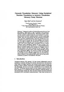
S21 S11 37-cm-long Cu coaxial Cu coaxialYBCO coplanar Cable Cable delay line
0.0 0
2
4 Time (ns)
6
8
Fig. 2. S21 and S11 step response of the 10-mm-wide 37-cm-long YBCO coplanar delay-line.
Attenuation (dB)
20 K 50 K 70 K 80 K
2
0.5
1
0 0
5
10 15 Frequency (GHz)
0.0 20
Surface Resistance (m W )
1.0
3
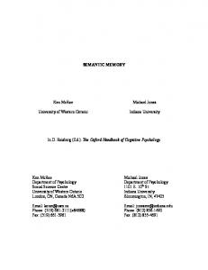
Fig. 3. Frequency dependence of the attenuation and the surface resistance measured at 20, 50, 70, and 80 K.
Since the 32-bit 10-GHz operation required 32 clocks for the entire loop delay and the register stage required 1 clock for retiming, the entire loop delay, excluding the retiming at the register stage, was calculated to be 3.1 ns with a cycle time of 0.1 ns. Ideally, the propagation delay of the crossbar switch should be accurately simulated by SPICE in advance so that the delay time of the YBCO line can be accurately designed. Also, the pulse propagation velocity in the YBCO coplanar line should be accurately estimated with a level of less than 10-4 by measuring the phase velocity using a YBCO coplanar transmission line resonator. Since the propagation delays of the ICs we used have not been released, however, we roughly estimated that the propagation delay of the crossbar switch, excluding the retiming, was 0.2 to 0.3 ns. Thus, the remainder of the entire delay is 2.8 to 2.9 ns, and this is the designed delay time of the delay line. Given the phase velocity of about 1.3´102 mm/ps in the YBCO coplanar line [6], we decided to use a delay-line length of 37 cm. For use in the 10-GHz 32-bit delay-line memory, we fabricated a 10-mm-wide 37-cm-long YBCO coplanar delay-line on a 4 mm x 8 mm MgO substrate, using a 0.5-mm-thick laser-ablated YBCO film. The same fabrication process was used as for the fabrication of the 5-mm-wide YBCO coplanar line [6]. The delay time, measured using time-domain step responses as shown in Figure 2, was 2.8 to 2.9 ns. This agrees well with the designed value, thus the pulse propagation velocity also agrees with the designed value of 1.3 x 102 mm/ps. Considering the ordinary size of the contact pads (100 mm x 100 mm or less), this value shows that the delay time can be easily Upper Wiring Layer Lower Wiring Layer
controlled with less than a 1-ps step. The characteristic impedance of this line, calculated from the S11 step response, is approximately 56 W. Considering the resistance increase (~60 W) of the 50-W terminators in the crossbar switch at low temperatures, which was measured in advance, the reflection wave according to the impedance mismatch is less than 5 % of a incident wave. Figure 3 shows the attenuation characteristics of this delay line. At a frequency of 10 GHz, the attenuation was 0.5, 0.8, 1.1, and 2.0 dB, respectively, at 20, 50, 70, and 80 K. The corresponding values of the surface resistance were 0.15, 0.26, 0.36, and 0.63 mW, respectively. Calculated from the surface resistance of 20 mW of normal Cu metal at 77 K, the attenuation of a Cu line with the same geometry would be about 63 dB. Considering this result, a delay line for use in this memory clearly must be made of a superconductor. B. 2 x 2-Crossbar Switch The crossbar switch was discretely formed using commercially available bare-chips of GaAs MESFET (metal-semiconductor field effect transistor) ICs, as shown in Fig. 1(b). These ICs, which handle the non-return-to-zero (NRZ) data format, were designed based on source coupled FET logic (Vlow=0.9 to1.0 V, Vhigh=0 V), and can operate with a clock rate of 10 GHz at room temperature. The ICs include internal termination resisters, which increases resistance from 50 W at room temperature to about 60 W at 77 K. The module of the crossbar switch was fabricated on a 23 mm x 23 mm goldplated alumina-ceramic substrate (Figure 4). The chips were connected by a combination of gold bonding-wires and two wiring layers patterned on stacked gold-plated alumina-ceramic substrates. The upper wiring layer mainly consists of 100-mm-wide coplanar transmission-lines used for high-speed internal links. The lower wiring layer is mainly for the dc power-supply connections and input/output ports. Since coplanar transmission lines were used, the ground plane is located parallel to these two layers. This crossbar switch takes a cross state (X) when the select signal S is “high” or “1,” and a bar state (=) when the select signal S is “low” or “0,” shown in Fig. 1(a). This module was packaged into a gold-plated brass housing (Fig. 4(b)) and tested by using a 4-channel 0.1 to 12.5GHz pulse pattern generator and a 50-GHz digital sampling oscilloscope. We confirmed this module operated normally with the clock rate of 10 GHz down to 45 K. The power consumption was approximately 7 W regardless of the operating speed and the temperature. The hardware quantity of this crossbar switch roughly
Bonding Wire
YBCO Delay Line
YBCO Delay Line
Crossbar Switch
MgO Substrate
GaAs IC
Alumina-Ceramics Substrate
(a) Fig. 4.
(b)
(a) Schematic cross-section, and (b) photograph of the delay-line memory module using the 10-mm-wide 37-cm-long YBCO coplanar line.
corresponds to that of 4.5 registers. Therefore, when a delay-line memory with a capacity of over 5 bits is fabricated, this memory will consume less power than the shift registers. C. Reentrant Superconducting Delay-line Memory The delay-line memory was assembled by attaching the YBCO delay-line chip on the crossbar switch module, as shown by the dashed line in Fig. 4(a). The measurements were carried out using the same configuration as in the crossbar switch testing. This memory operates as a 32-bit buffer memory at a clock rate of 10 GHz and a temperature of 46 K, as shown in Figure 5. In Fig. 5, the strings consisting of two high-voltage signals or “11” at the head and end of the Din and Dout graphs are the markers pointing to the top and end of a cyclic data frame. The 32-bit NRZ data-packet strings consisted of (11111111 01010101 00110011 00001111) and were input to Din. In case (a), since the select data S are in the bar state (=) all the time, the output data Dout are the same as Din. Thus, the 32-bit packet pass through the memory without buffering. In case (b), the crossbar switch is in the cross (X) state during first and second 32clock slots. During the first 32-clock slot, the 32-bit data-packet goes into the delay line and is buffered. Then, during the second 32-clock slot, this 32-bit data-packet goes to Dout. In case (c), the data-packet is buffered with a two-packet length (64 clocks), then goes to Dout. Cases (b) and (c) show the 10-GHz 32-bit buffer memory operation. Furthermore, this memory operated as a 40-bit 12.5-GHz buffer memory at 50 K. This clock rate is several times higher than the maximum clock rate of the conventional shift register circuits reported to date. (V)
32-bit data
0
32 clock
Din -1 0
(a) S
Marker
=
X
X
=
X
=
X
-1 0
Dout -1 0
(b) S -1 0
Dout -1 0
(c) S -1 0
Dout -1
3.2 ns/div. (32 clk/div.)
Fig. 5. 32-bit 10-GHz buffering operation of the delay-line memory; (a) unbuffering operation, and (b) buffering operation during a packet length (32 clock), and (c) buffering operation during double packet length (64 clock).
IV. CONCLUSIONS In this report, we proposed using a superconducting delay-line memory as an ATM cell buffer memory in high-speed ATM switching systems. This is because the superconducting delay-line memory is potentially superior to conventional semiconductor memories such as register files, as regards the scalability of both memory capacity and operating speed. We have successfully designed and fabricated such a delay-line memory using a 10-mm-wide 37-cm-long YBCO coplanar line and commercially-available GaAs MESFET ICs. This memory operated as a 32-bit 10-GHz buffer memory at 46 K and as a 40-bit 12.5-GHz buffer memory at 50 K. These crock rates are higher than the maximum clock rate of any conventional shift register circuit reported to date. This result shows that the superconducting delayline memory is a powerful candidate for use in high-speed cell buffer storage in an ATM switch with aggregate throughput over 1 Tbit/s. ACKNOWLEDGMENT We thank Jun’ich Sone for his continuous encouragement. REFERENCES [1] E. Munter, J. Parker, and P. Kirkby, “A high-capacity ATM switch based on advanced electronic and optical technologies,” IEEE Commun. Mag., vol. 33, pp. 64-71, Nov. 1995. [2] W. Hattori, T. Yoshitake, and S. Tahara, “Fabrication of a 5-mm-wide YBCO coplanar delay line,” Advances in Superconductivity IX, S. Nakajima and M. Murakami, Eds. Tokyo: Springer-Verlag, 1997, pp. 1319-1322. [3] M. J. Burns, K. Char, B. F. Cole, W. S. Ruby, and S. A. Sachtjen, “Multichip module using multilayer YBa2Cu3O7-d interconnects,” Appl. Phys. Lett., 62, pp. 1435-1437, March 1993. [4] S. K. Tewksbury, L. A. Hornak, L. A. Tewksbury, and L. Chen, “A System-Level Evaluation of HTS Interconnections on MCMs for High Performance VLSI Systems,” Journal of Microelectronic Systems Integration, Vol. 4, No. 2, 1996. [5] J. W. Cooksey, S. S. Scott, W. D. Brown, S. S. Ang, R. G. Florence, S. Afonso, “Recent Advances in High Temperature Superconductor Multichip Modules,” 6th International Conference on Multichip Modules, pp. 115-120, 1997. [6] W. Hattori, T. Yoshitake, and S.Tahara, “A 5-mm-wide 18-cm-long Low-loss YBa2Cu3O7-d Coplanar Line for Future Multichip Module Technology,” to be published in IEEE Trans. Appl. Supercond., September 1998. [7] A. Metzger, C. E. Chang, P. M. Asbeck, K. C. Wang, K. Pedrotti, A. Price, A. Campana, D. Wu, J. Liu, and S. Beccue, “A 10 Gb/s 12´12 cross-point switch implemented with AlGaAs/GaAs heterojunction bipolar transistors,” 1997 GaAs IC Symposium, pp. 109-112, 1997. [8] K. S. Lowe, “A GaAs HBT 16´16 10 Gb/s/channel crosspoint switch,” IEEE J. Solid-State Circuits, vol. 32, no.8 pp.1263-1268, Aug. 1997. [9] Y. Watanabe, Y. Nakasha, Y. Kato, K. Odani, and M. Abe, “A 9.6-GB/s HEMT ATM Switch LSI with Event-Controlled FIFO,” IEEE J. Solid-State Circuits, vol. 28, no.9, Sep. 1993. [10] H. Yamada, M. Tsunotani, F. Kaneyama, and S. Seki, “20.8 Gb/s GaAs LSI’s SelfRouting Switch for ATM Switching System,” IEEE J. Solid-State Circuits, vol. 32, no. 1, Jan. 1997. [11] R. A. Thompson and P. P. Giordano, “An experimental photonic time-slot interchanger using optical fibers as reentrant delay-line memories,” IEEE J. Lightwave Technol., vol. LT-5, no. 1 pp.154-162, Jan. 1987. [12] K. L. Hall, J. P. Donnelly, S. H. Groves, C. I. Fennelly, R. J. Bailey, and A. Napoleone, “40-Gbit/s all-optical circulating shift register with an inverter,” Optics Letters, vol. 22, no. 19, pp. 1479-1481, Oct.1997. [13] For example, K. Murata, T. Otsuji, E. Sano, M. Ohhata, M. Togashi, M. Suzuki, “A Novel High-Speed Latching Operation Flip-Flop (HLO-FF) Circuit and its Application to a 19-Gb/s Decision Circuit Using a 0.2-mm GaAs MESFET,” IEEE J. Solid-State Circuits, vol. 30, no. 10, Oct. 1995.