A Reference Measurement Data Set for Multisensor Pedestrian Navigation with Accurate Ground Truth Michael Angermann, Anne Friese, Mohammed Khider, Bernhard Krach, Klaus Krack, Patrick Robertson
BIOGRAPHY Michael Angermann, Mohammed Khider, Bernhard Krach and Patrick Robertson are with German Aerospace Center’s Institute of Communication and Navigation, 82234 Wessling, Germany, E-mail:
[email protected]. Anne Friese and Klaus Krack are with Universität der Bundeswehr München, 85577 Neubiberg, Germany. Correspondence Author: Michael Angermann
ABSTRACT This paper presents a measurement dataset for testing and evaluating multi-sensor approaches in pedestrian navigation. The measurements include both transitions from outdoor to indoor and vice versa. Furthermore, segments with explicit threedimensional character, such as ramps, stairs and elevators are included. The measurements have been carried out in and around a lab and office building. Ground truth reference points are provided with sub-centimeter accuracy. The results of two implementations of Bayesian filter algorithms (EKF and Particle filter) are provided for reference purposes. All measurements and background data are publicly available via an accompanying website.
1. INTRODUCTION Supporting pedestrians navigating, both in indoor and outdoor environments may be considered the next step in the evolution of personal navigation systems. Particularly challenging is the fact that satellite-based navigation is often impossible in places where navigation support would be very desirable, such as inside airports, subway stations or large public buildings. Several research groups have
recently achieved compelling results in pedestrian navigation with various combinations of sensors and algorithms [Beau07, Fox05, GLC06, Kra08b]. Collecting sensor data for testing and evaluating multisensor approaches often requires tedious interfacing to several sensors, as well as accurate ground truthing of a pedestrian’s position. We have more than once undergone this process and believe that public availability of such data allows the scientific community to progress more quickly by focusing on the development of improved algorithms. With this paper and its accompanying datasets we intend to improve and encourage the comparability of algorithms and their specific implementations. We therefore make all involved data available via an accompanying website. In order to encourage other researchers to evaluate the performance of their algorithms we have also included the output of two position estimator implementations. One position estimator is based on a an Extended Kalman Filter, the other on a particlefilter. While both implementations employ the same subset of sensors, only the Particle Filter utilizes an advanced movement model based on the building’s floor plans. The data is organized in several datasets including ground truth reference points (GTRP), building geometry and sensor outputs. In order to cover a wide range of application scenarios, our measurements specifically include the important transitions from outdoor to indoor and vice versa. Furthermore, we have included segments with explicit three-dimensional character, such as ramps, stairs and elevators. The remainder of this paper is organized as follows: In Section 2 we describe the environment in which the measurements took place, the character and quality of the ground truth data and gives an overview of the sequence of segments in the
scenario. All involved sensors are briefly described in Section 3, whereas the actual datasets for the sensors are discussed in Section 4. For further reference purposes we give the results of two different Bayesian filter algorithms, namely an Extended Kalman Filter (EKF) and a sequential Monte–Carlo (“Particle”) filter in Section 5 and close with some conclusions and an outlook in Section 6.
2. ENVIRONMENT, GROUND TRUTH DATA AND SCENARIO The measurement data has been collected inside and in close proximity of our lab and office building in Oberpfaffenhofen, Germany. We have placed a dense set of reference points inside and around the building. For the measurements that accompany this paper, 57 of these points have been utilized as ground truth reference points (GTRPs). In order to keep these GTRPs useful for future, and more accurate algorithms and sensors, the GTRPs’ positions have been carefully measured to sub-centimeter accuracy with geodetic surveying equipment (Leica System 1200 SmartStation), employing differential GPS (SAPOS) for outdoor measurements, as well as optical distance and angular measurements.
Building geometry, i.e. walls, stairs, doors, or passages has been derived from architectural scale drawings of the building. We have represented this information as vector data in a minimalistic, easyto-parse XML-format. In our work we make dual usage of this data: Firstly, we use it as visual overlay when plotting location estimates. Secondly, we incorporate it as a priori knowledge incorporated into the transition/movement models of our sequential Monte-Carlo filter [AKL03, KKRA08]. Furthermore, we have placed a set of active RFIDtags within the building. The positions of these tags are also represented in an XML-format. The scenario of the reference data set starts from a GTRP outside of the building with good GPScoverage and already acquired GPS-receiver. After a short walk the person enters the office building. The person then walks through the corridor in the lower floor and subsequently climbs the stairs to the second floor. After a similar walk on the second floor, the person reaches the elevator. The elevator goes up to the third floor (picking up another passenger), then goes down to the garage level. The person leaves the elevator and then performs a short meandering walk in the garage. Finally the person leaves the garage via the ramp and returns to the starting position.
3. SENSORS In order to enable the analysis and comparison of hopefully many algorithms and implementations, we have included a wide range of sensors, namely triads of accelerometers and gyroscopes mounted at various positions, magnetometers, a barometer, a GPS-receiver, an RFID-Reader and a camera. All sensors were more or less loosely mounted on the pedestrian. This approach should enable to pick the subset of sensors one considers interesting and feed the respective subset of data to the algorithm under investigation.
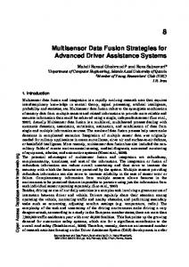
3.1 GPS Figure 1: Building geometry, ground truth reference points (blue), both inside and outside of the building and positions of RFIDtags (red) are shown.
The pedestrian was equipped with a commercial GPS receiver (µBlox 5 evaluation kit, EVK-5H [Ublox]). The receiver was connected to a small patch antenna mounted on a shoulder strap of a carrying device (similar to a vendor’s tray) we were
using for carrying the logging PC. Data has been retrieved with 1 Hz using the NMEA 0183 data format. 3.2 INERTIAL MEASUREMENTS UNITS We have utilized two different types (MTX, by XSense [Xsense] and InertiaCube3, by InterSense [Intersense]) of inertial measurements units (IMUs). One “MTX” was mounted on each foot of the pedestrian. An additional “InertiaCube3” was carried in the pocket of the pedestrian. All involved IMUs are equipped with three-axis accelerometers and three-axis gyrometers. Both accelerometers and gyrometers are realized by commercial-off-the-shelf micro-electro-mechanical systems (MEMS). Each IMU is additionally equipped with a three-axis magnetic field sensor. 3.3 ELECTRONIC COMPASS
4. MEASUREMENT DATA SETS
In this section we give an overview on the available measurement data sets for the various sensors. All sensor measurements have been time-stamped. In addition to the data of the actual sensors, timestamps have been recorded whenever the pedestrian walked over a GTRP. In conjunction with the accurate locations of the GTRPs, these timestamps provide the ground truth data points at which positions errors of any position estimation algorithm working on the sensor data can be accurately determined. Figure 2 shows the number of available satellites as reported by the GPS receiver. While tracking up to 10 satellites when the pedestrian is outdoors, the GPS receiver looses lock and cannot track any satellites, when the building is entered. The receiver does not re-acquire any satellite during the indoor segment and takes significant time to re-acquire satellites when returning from indoors to outdoors.
We have mounted an additional three-axis magnetic field sensor (OS5000-US, by Ocean Server Technology [OST]) on the hip of the pedestrian. This sensor is packaged with an additional threeaxis MEMS-based accelerometer.
3.4 ALTIMETER Both pressure and temperature were measured by an altimeter sensor package (USB Evaluation Kit for MS5540-C, by Intersema [Intersema]) carried by the pedestrian.
3.5 ACTIVE RFID TAGS On one of the stories of our building we have distributed a number of active RFID tags at a spacing of approximately 2-4 meters and in known locations. These tags respond to interrogation by a PCMCIA format reader (i-Card III from Identec Solutions [Identec]) which is able to detect the presence and signal-strength of many such tags (of type Identec i-D2) within its range of up to typically 10 meters. In [Wend07] it has been previously shown how such an approach can be used to achieve reasonable accuracy in buildings.
Figure 2: Number of available satellites as reported by the GPS receiver. The grayshaded area denotes the indoor-segment of the walk. It can be seen that the GPS receiver looses lock and cannot track any satellites, when the building is entered. We can also see that it takes significant time to re-acquire satellites when returning from indoors to outdoors.
The reported heading of the electronic compass, depicted in Figure 3, is fairly noisy, especially when moving in the building, presumably due to the presence of electric currents and ferromagnetic material, such as iron. However, we can see that this heading is drift-free, when comparing the beginning and end of the data set (the pedestrian intentionally rotated to face a predetermined direction at the beginning and end of the walk).
Figure 3: Plot of the heading as reported by the electronic compass. The gray-shaded area denotes the indoor-segment of the walk.
Figure 4 shows the turn rates reported over the duration of 8 seconds by one of the foot-mounted IMUs. The turn rates are defined with respect to the three axes of the IMU. We can see the stride of the person and the brief durations where the foot is at rest, i.e. all three turn rates are close to zero. The same rest phases are visible in the accelerometer measurements depicted in Figure 5. Detecting these rest phases is the key to perform the Zero Velocity Updates (ZUPTs) for the purpose of estimating and compensating for the drift-errors of the IMU.
Figure 4: Plot of turn rates with respect to the three axes of the IMU over a duration of 8 seconds, as reported by one of the footmounted IMUs. Clearly visible is the stride of the pedestrian.
Figure 5: Plot of accelerations in the three axes of the IMU over a duration of 8 seconds, as reported by one of the foot-mounted IMUs. Clearly visible is the stride of the pedestrian and the correspondence to the turn rates, depicted in Figure 4. In addition to the accelerations caused by the pedestrian’s stride, the vertical movement during an elevator ride is visible in the measurements of the accelerometers. We can see how the elevator speeds up at the beginning, then travels with constant speed, i.e. zero acceleration, for approximately 20 seconds and then slows down again at the end of the ride. Due to the fact that the IMU is only roughly aligned with the horizontal plane, the vertical acceleration of the elevator is not only visible in the Z-Axis of the IMU but also on its X-Axis and Y-Axis.
Figure 6: Accelerations as reported by one of the foot-mounted IMUs during the “down” segment of the elevator ride. Note that the IMU is only roughly aligned with the horizontal plane. As a result, the vertical acceleration of the elevator is not only visible in the Z-Axis of the IMU but also on the XAxis and Y-Axis. When the pedestrian climbs the stairs, rides the elevator up and down and walks up the ramp, the resulting changes in altitude are also visible in the
measurements taken with the altimeter and plotted in Figure 7.
available for comparison, as well as scripts for evaluating and plotting statistics. We present in this paper an exemplary result from our particle filter and EKF reference system, but deliberately without using RFID tags. Effectively, this means that our positioning system is infrastructure-less, drawing on sensors, GPS, and information from an accurate building layout.
Figure 7: Plot of the altitude as reported by the altimeter (computed from the temperature and pressure measurements). Clearly visible is the stairway (“stairs”), the “up” and “down” segments of the elevator ride, and the walk up the ramp, exiting the garage. The gray-shaded area denotes the indoor-segment of the walk. A further dataset contains recorded relative signal strength indications (RSSI values) as reported by the RFID-reader.
5. REFERENCE ESTIMATION
The error growth over time is shown in Figure 8 with the data collected during a walk from outside, into a building (after ~75 secs.), walking on several levels in the building including stairs and elevator, walking through a large and mainly wall-less underground car park (~350 s.) and finally back into the open again (~380 s.). We can see how the EKF diverges once the GPS signal is lost, whereas the PF that constrains motion using knowledge of the walls and their location remains very accurate. In fact the accuracy is best (~1 m.) while walking in the heavily constrained part of the building (mainly corridor areas) and increases to 3-5 meters in the open underground car park. Once outside the GPS is again received and good accuracy is once again achieved also for the EKF. In Figure 9 we have shown the associated cumulative error probability.
We have processed the measured data of a subset of the sensors with our own, previously published cascaded position estimation system for a footmounted inertial measurement unit (IMU) [Kra08b], as well as for a system using active RFID tags that are placed in known locations in the infrastructure [Wend07]. This system encompasses an inertial navigation system (INS), Kalman-filter and Zero Velocity Update (ZUPT) detector working at the high rate of the inertial sensors. A particle filter working at a lower rate (~1 second) is then used to combine the output of this Kalman-Filter with measurements from an electronic compass, GPS, barometer and RFID signal strength measurements. The particle filter employs a mobility model that uses map information wherever available. We have chosen a proposal density that is determined by the INS and its associated narrow Gaussian error distribution (in the spirit of the “Likelihood Particle Filter” [Ara02]). As reference, we have employed an EKF as a reference that is unable to take into account the restriction of motion by the walls. The output of this system as well as its statistics is made
Figure 8: Plot of the position error over time for a mixed outdoor / indoor walk for an infrastructure-less approach (i.e. not taking any RFID measurements into account). The Particle Filter (PF) achieves better performance than the EKF whilst indoors due to constraining motion using building layout knowledge.
[Beau07] S. Beauregard, “Omnidirectional pedestrian navigation for first responders,” in Proceedings of the 4th Workshop on Positioning, Navigation and Communication, 2007, WPNC07, Hannover, Germany, Mar. 2007, pp. 33–36 [Fox05] E. Foxlin, “Pedestrian tracking with shoemounted inertial sensors,” IEEE Computer Graphics and Applications, vol. 25, no. 6, pp. 38–46, Nov. 2005
Figure 9: Cumulative error probability of the position error in the same experiment as shown in Figure 8. 6. CONCLUSIONS AND OUTLOOK We have performed and presented a range of measurements, including the critical transitions from outdoor to indoor and vice versa. Furthermore, we have included segments with explicit threedimensional character, such as ramps, stairs and elevators. Since we want to encourage other researchers to test their algorithms with our measurement data, we offer to host their resulting datasets as well as ours on the following, publicly available website: http://www.kn-s.dlr.de/indoornav/ We are confident that the sharing of measurements datasets and results will prove to be useful for objective comparison and stimulate a host of novel algorithms and implementations that will lead to a more rapid advance of the field.
REFERENCES [AKL03] M. Angermann, J. Kammann, B. Lami, "A New Mobility Model Based on Maps", Proceedings of the 58th IEEE Semiannual Vehicular Technology Conference (VTC Fall 2003), Orlanda, USA, October 6-9, 2003 [Ara02] M.S. Arulampalam, S. Maskell, N. Gordon, T. Clapp, "A tutorial on particle filters for online nonlinear/non-Gaussian Bayesian tracking". IEEE Transactions on Signal Processing. 50 (2), 2002. pp. 174–188. doi:10.1109/78.978374
[GLC06] S. Godha, G. Lachapelle, and M. E. Cannon, “Integrated GPS/INS system for pedestrian navigation in a signal degraded environment,” in Proceedings of the 19th International Technical Meeting of the Satellite Division of the Institute of Navigation ION GNSS 2006, Fort Worth, Texas, USA, Sept. 2006 [Identec] http://www.identecsolutions.com/ [Intersema] http://www.intersema.ch/ [Intersense] http://www.intersense.com/ [KKRA08] M. Khider, S. Kaiser, P. Robertson, M. Angermann, “A Novel Movement Model for Pedestrians Suitable for Personal Navigation”, ION NTM 2008, San Diego, California, Jan. 2008 [Kra08b] B. Krach and P. Robertson, “Cascaded Estimation Architecture for Integration of FootMounted Inertial Sensors”, Proc. 2008 IEEE/ION Position Location and Navigation Symposium (IEEE/ION PLANS 2008), Monterey, California, USA, Mai 2008 [OST] http://www.ocean-server.com/ [ROAW02] P. Robertson, A. Ouhmich, M. Angermann, and K. Wendlandt, “Implementation of soft location on mobile devices,” in International Symposium on Indoor Localization and Position Finding, InLoc 2002, DGON, Bonn/Germany, July 2002. [Ublox] http://www.u-blox.com/ [Wend07] K. Wendlandt, P. Robertson, M. Khider, M. Angermann and K. Sukchaya, “Demonstration of a Realtime Active-Tag RFID, Java Based Indoor Localization System using Particle Filtering”, Adjunct Proc. 9th International Conference on Ubiquitous Computing (UBICOMP 2007), Innsbruck, Austria, Sep. 2007 [Xsens] http://www.xsens.com/