IEEE Transactions on Dielectrics and Electrical Insulation
Vol. 22, No. 4; August 2015
1907
A Repetitive Microsecond Pulse Generator for Atmospheric Pressure Plasma Jets Cheng Zhang, Tao Shao, Ruixue Wang, Weimin Huang Institute of Electrical Engineering, Chinese Academy of Sciences Key Laboratory of Power Electronics and Electric Drives, Chinese Academy of Sciences Beijing, 100190, China
Zongtao Niu Zhengzhou University Henan, 450001, China and Edl Schamiloglu Department of Electrical & Computer Engineering, University of New Mexico Albuquerque, NM 87131 USA
ABSTRACT Compared with other non-thermal plasma sources, the atmospheric-pressure plasma jet (APPJ) has advantages on simple structure, low temperatures, strong chemical activities, and convenient handling, all of which have attracted much attention. The power sources play an important role on the characteristics and the applications of the APPJ. In this article, a compact repetitive microsecond-pulse generator is designed for exciting the APPJ in helium and argon. The microsecond-pulse generator can produce repetitive pulses with output voltages of up to 20 kV, pulse width of ~8 ȝs, and pulse repetition frequencies (PRFs) of 1 Hz ~2 kHz. Using the designed repetitive microsecond-pulse generator, the characteristics of the APPJ are investigated by measuring the voltages and currents and obtaining images of the discharges. Experimental results show that the microsecond-pulse generator has been successfully used to sustain stable APPJs both in helium and argon. The shape of the output voltage pulses may change as the applied voltage increases. Nevertheless, the output voltages are stable at all PRFs when the applied voltage is fixed. Furthermore, the effects of flow rate, the applied voltage, and the PRF on the He/Ar APPJ are investigated. Results show that it is more likely to generate a He APPJ rather than an Ar APPJ under microsecond-pulse excitation. The length of the plasma plume is slightly affected by the PRF both in the He APPJ and the Ar APPJ. Index Terms - Gas discharge, Non-thermal plasma, Microsecond pulse, Pulsed power, Atmospheric-pressure plasma jet (APPJ), Pulse repetition frequency (PRF).
1 INTRODUCTION THE atmospheric-pressure plasma jet (APPJ) has extensive applications in the fields of biomedical treatment, surface modification, air cleaning, and sterilization [1-5]. The behavior of the discharge in the applications mentioned above is closely related to the characteristics of the APPJ. The power source is one of the important parameters that can influence the characteristics of the APPJ because it can play a key role on the discharge and ionization characteristics [6-10]. In Manuscript received on 31 October 2014, in final form 18 December 2014, accepted 19 December 2014.
general, APPJs are generated by a direct-current (DC) generator, alternating-current (AC) generator, radio-frequency (RF) generator, and microwave generator. Recently, pulsed generators have become more and more popular for the excitation of non-thermal plasmas at atmospheric pressure. These kinds of generators not only produce high reduced electric fields, but also control the generation time of the nonthermal plasmas and their chemical and physical reaction times [11-13]. Therefore, pulsed generators are considered as an efficient excitation source in many non-plasma applications [14-15]. As to the generation of APPJs, in most cases, the DC generator, RF generator, and AC generator usually produce a
DOI 10.1109/TDEI.2014.005042
1908
C. Zhang et al.: A Repetitive Microsecond Pulse Generator for Atmospheric Pressure Plasma Jets
high voltage with amplitude less than 10 kV and with average power of several hundreds watts. Compared to these generators, pulsed generator can produce high instantaneous power (up to several tens of kilowatts) and low average power (several hundred watts to several kilowatts), which is beneficial for controlling the generation and the reaction of the plasmas. Moreover, pulsed generators can offer fast rise time to make highly elevated applied voltages and large reduced electric fields (E/N); thus, it is more likely to obtain both high electron density and desirable active plasma chemistries in the APPJ with pulsed generator excitation [1618]. Walsh et al compared the electrical characteristics of a cold APPJ sustained by pulsed and AC generators. It was concluded that pulsed excitation could reduce electrical energy consumption for producing the same amount of oxygen atom [16]. Karakas et al presented the evolution of the APPJ and measured its jet current. The generator produced output pulse with a duration of 2 ȝs and a repetition rate of 5 kHz. They found that an ionization wave propagated along the plasma jet and the electron density of the plasma bullet was of the order of 1016 mí3 [17]. Lu et al investigated the effect of pulse width on the plume length of the pulsed APPJ (and the pulse width ranged from 100 ns to 200 ȝs) and they found that the plume length increased with pulse width until it reached a saturation value when the pulse width was 4 ȝs [18]. From the aforementioned studies, the development of a power source technology closely meeting the requirements of the mechanism and application of the APPJ can be found. Thus, in order to meet the growing demand for plasma applications, different requirements can be made for pulsed power sources [19-25]. The parameters of the pulsed power supply are closely related the gas-discharge devices. Different varieties of pulsed generators with different parameters and different technical solutions have been developed, such as Marx’s generator, generators on magnetic pulse compression and generators on switches (reed, spark gap, and solid state) [26]. In our previous work, a comparison of the nanosecondpulse and microsecond-pulse generators was conducted to analyze the effect of the pulse parameters of the pulsed generator, and the nanosecond-pulse generator could excite higher concentration of excited OH radicals and atomic oxygen in the active plume zone than the microsecond-pulse generator [27-28]. However, the nanosecond generator based on a magnetic pulse compression system is complex; compact repetitive pulsed generators with reduced size are of greater
interest. In this article, a compact low-power microsecondpulse generator is developed by using semiconductor switches and pulse transformers. The generator is used to generate stable APPJs in helium and argon.
Figure 1. Schematic circuit of the pulsed power generator
2 DESIGN OF MICROSECOND-PULSE GENERATOR 2.1 DESIGN OF THE MAIN CIRCUIT Figure 1 shows the schematic of the main circuit of the pulsed generator. In general, the pulsed power source device includes the following parts: primary energy storage system, intermediate energy storage system, pulse shaping system, switching system, measurement and protection system, and the load [29-30]. The energy is stored in the primary energy storage system, which is formed by the intermediate energy storage system and the pulse shaping system. The switching system controls the pulse transformer to pulse shaping and compression, and then, a desired pulse is obtained on the load. Figure 2 presents the main circuit of the microsecond-pulse generator in this article. An AC variac power source provides the energy for the entire power supply. A single-phase voltage regulator feeds the rectifier bridge for charging the primary energy storage. The primary energy storage system includes a rectifier bridge, a resistor R1, a primary capacitor C1, and a leakage resistor R2. In order to generate repetitive microsecond-pulses, C1 should be charged between the continuous pulses; thus, the charging time should be short and the charging current should not be large. In our design, an auxiliary circuit is used to achieve the charging and discharging of C1, which fulfills the requirement of the charging time and charging current. In this circuit, switch SW1 is a normally closed switch, and switch SW2 is a normally open switch. At the appropriate time, R2 is connected and the indicator light “Red” is on. When the main circuit of the generator is operational, SW2 is closed, and the indicator light
Figure 2. The main circuit of low-power microsecond-pulse generator.
IEEE Transactions on Dielectrics and Electrical Insulation
Vol. 22, No. 4; August 2015
“Green” is on. At that time, the generator operates in a repetitive mode, C1 is charged immediately after it discharges, guaranteeing a low voltage fluctuation. Thus, C1 is equivalent to a constant DC voltage source. The intermediate storage system includes a semiconductor switch S (IGBT), an inductor L, a diode D1 and a secondary capacitance C2. When the switch S turns off, C1, L, C2 and the primary side of the pulse transformer (PT) consist of a resonant circuit, which charges C2. When switch S turns on, C2, S and the primary side of PT consist of a discharge circuit. In the discharge process, most of the energy is delivered to the load through the coupled pulse transformer. The switching system consists of an auxiliary switching circuit, a trigger pulse circuit, and the semiconductor switch. This switching system takes responsibility for forming the primary pulse of the main circuit and controlling the PRF of the generator. The pulse shaping and compression depends on the pulse transformer, which will be given in detail in the following section. In addition, the power absorbing and protection circuit includes a resistor R and a capacitor C3, forming a buffer circuit and reducing overvoltage produced by the switching.
Figure 3. Pulsed transformer design. 1 is transformer secondary winding, 2 is transformer insulating stents, 3 is transformer cores, 4 is the transformers outer insulation layer, 5 is the transformer insulation layer, and 6 is transformer primary winding.
2.2 DESIGN OF THE PULSE TRANSFORMER As to the pulsed generator based on the pulse shaping and compression, the pulse transformer plays an important role on the determination of the output characteristics of the
1909
generator. The core material and winding of the pulse transformer affect the electromagnetic processes in it. Generally, the pulse transformer core is high speed and asymmetric. The magnetization curve of the pulse transformer core can be found in [31]. It was concluded that the material of the pulse transformer core should fulfill the requirements as follows: a high saturation magnetic flux density, a low residual magnetic flux density, a small coercive force, and a high equivalent conductivity. In our case, a soft material is chosen. Usually, soft materials include silicon steel, ferrite, permalloy, amorphous and nanocrystalline soft magnetic alloy. From the view of best performance, Fe-based nanocrystalline alloys could be used. However, from the view point of commerce, the best overall performance on the market is amorphous and nanocrystalline soft magnetic alloy. Therefore, the amorphous alloy material is chosen as the pulse transformer core for the microsecond-pulse generator. The shape of the pulse transformer core is toroidal, and both the primary winding and the secondary winding are coupled on the ring [32]. As a result, insulation between the transformer winding and the transformer core must be taken into account. Figure 3 shows a schematic of the insulation design. It can be seen that insulation stents are used to isolate the transformer winding and the transformer core because of the dry-type transformer used in our case. Furthermore, some insulation layers are used to block each winding. 2.3 SIMULATION OF MICROSECOND GENERATOR An electrical circuit simulation is performed based on the PSpice software. The electrical circuit is presented in Figure 4. In the simulation, C1 is 680 ȝF, L1 is 300 ȝH, C2 is 0.47ȝF, and the pulse transformer is established through a selfmodeled non-linear core. The saturation magnetization is 10000 GS, the residual magnetic flux density BR is 5000 GS, the coercive force is 0.2 Oe, and the effective cross-sectional area is 8.2 cm2. The outer diameter and the inner diameter of the toroidal core are 140 mm and 80 mm, respectively. The turn ratio of the pulse transformer is 2/50, and the primary and secondary leakage inductances are 1 ȝH and 8.2 mH, respectively. Figure 5 shows the experimental and simulated output results of the microsecond-pulse generator, and the voltages of the load and capacitor C2 are detected. In Figure 5a, when the switch turns on at 10 ȝs, the voltage of C2 gradually decreases to zero, and then is reversely charged to
Figure 4. Simulation diagram of the microsecond-pulse generator.
1910
C. Zhang et al.: A Repetitive Microsecond Pulse Generator for Atmospheric Pressure Plasma Jets
500 V. After 20ȝs, the switch turns off and C2 charges to about 800 V again. At this time, the output voltage on the load is about 22 kV. Figure 5b shows the measured voltages when no load exists. The output voltage is measured by a Tektronix probe (P6015A) and the voltage of C2 is measured by another Tektronix probe (P5200A). The experimental conditions were as follows: the input voltage is 350 V, the PRF is 500 Hz, and the trigger pulse is 20 ȝs. It can be seen that the output voltage is about 20 kV. The rise time is about 1 ȝs and the pulse width is 6 ȝs. The experimental result is consistent with the simulation data. Some differences between the experimental and simulated waveforms can be attributed to stray parameters in the experiment. The parameters of the output voltage, such as the amplitude, the rise time and the pulse width, are suitable for the further generation of the microsecond-pulse APPJ.
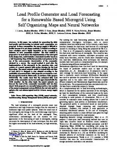
Figure 7. Typical voltage-current waveform and discharge image of the He APPJ.
Figure 8. Discharge images of the He APPJ at different gas flows. Figure 5. Simulated (a) and experimental (b) voltage on the load and across the capacitor C2.
Figure 6. Schematic view of the experiment set-up and the measurement system.
3 GENERATION OF MICROSECOND-PULSE APPJ In this section, the repetitive microsecond-pulse generator designed described previously is used to investigate the characteristics of the APPJ in helium and argon. The
schematic experimental set-up is shown in Figure 6. The structure of the APPJ is a simple coaxial-type, and the details of the arrangement are as follows: a T-shaped cylindrical quartz tube is fixed in a polymethylmethacrylate column, and the tube has an inner diameter of 5 mm, an outer diameter of 8 mm, and a length of 15 cm. A copper needle with a length of 15 cm and a diameter of 2 mm is located in the center of the tube and fixed in that place by a rubber plug. The distance between the electrode end face and the tube nozzle is 15 mm. The end of the copper needle is connected to the high voltage output of the microsecond-pulse generator. No grounded electrode exists in the discharge unit. The gas supply and measurement system are also shown in Figure 6. The working gas, helium (99.999%) and argon (99.99%), is controlled by a Sevenstar D08-4F mass flow meter. The flow rate of the working gas ranges from 0 to 15 standard liters per minute (SLM). The applied voltage, discharge current, and discharge image are recorded in the experiments. The applied voltage at the high-voltage electrode is measured by a Tektronix P6015 high-voltage probe. The discharge current is measured by a Pearson Model 6595 current probe, which has a rise time of 2.5 ns and a current-tovoltage ratio of 0.2 A to 1 V. A Lecroy WR204Xi with a
IEEE Transactions on Dielectrics and Electrical Insulation
Vol. 22, No. 4; August 2015
bandwidth of 2 GHz and a time resolution of 10 GS/s is used to record these signals. The images are taken by a Canon EOS500D digital camera with a Tamron Lens (Model A001), and the distance between the camera and the discharge region is 1 m. 3.1 GENERATION OF He APPJs Figure 7 shows the typical voltage-current waveforms and discharge image of the APPJ in helium. The experimental conditions were as follows: the applied voltage was 8 kV, the PRF was 1 kHz, the trigger pulse width was 20 ȝs, and the gas flow rate was 4 L / min. It can be seen that the total current occurred at the rise time of applied voltage, and its amplitude is 0.33 A. Furthermore, the jet current was calculated by subtracting the displacement current from the total current in the experiments. The displacement current was the measured current of the discharge when there was no gas flow and no plasma jet was generated [27-28, 33]. It can be observed that the amplitude of the displacement current is 0.27 A, which is much larger than that of the jet current (0.1 A), as show in Figure 7b. Note that, there is no secondary discharge appearing in the jet current, which indicates no secondary
Figure 9. Dependence of the applied voltage on the characteristics of the He APPJ.
1911
discharge exists on the falling-edge of the voltage. The discharge image illustrates that a contracted plasma channel appears in the ambient air, indicating that a stable He APPJ was generated. The length of the plasma plumes is 6.3 cm, which is longer than that of the microsecond-pulse He APPJ in our previous experimental results [27]. We believe that the difference is due to the diameter of the tube and the flow rate. In this article, the diameter of the tube is larger than that reported in [27]; the Reynolds number decreases with increasing diameter of the tube; thus, the plasma plume described in this article is more stable than that reported in [27]. Moreover, the flow rate here is a little larger than that of our previous results, which may affect the plasma plumes. Figure 8 shows discharge images at different flow rates. The experimental conditions were the same as those in Figure 7, except the flow rate ranged from 2 L/min to 12 L/min. The dashed white line indicates the location of the nozzle. It can be observed that the length of the plasma plume is 4.8 cm when the flow rate is 2 L/min, and it increases with flow rate until it reaches 8 cm when the flow rate is 6 L/min. After that the length of the plasma plume decreases with increasing flow
Figure 10. Dependence of the PRF on the characteristics of the He APPJ.
1912
C. Zhang et al.: A Repetitive Microsecond Pulse Generator for Atmospheric Pressure Plasma Jets
rate. This observation is consistent with the results of the experiment conducted by Li et al using a sinusoidal high voltage with a frequency of ~50 kHz [34]. Reynolds number reflects the effect of the flow rate on the discharge. In our cases, the Reynolds number was 758, 2274 and 4548 when the flow rate was 2, 6, 12 L/min, respectively. Note that the APPJ operated in the Laminar mode when the flow rate is less than 6 L/min; afterwards the discharge mode begins to transition to a turbulent mode. In this case, the APPJ length increases with gas flow rate because the jet’s equivalent stiffness increases with gas flow rate [34]. Thus, a longer plasma plume can be obtained here compared to our previous work [27]. The effect of the applied voltage on the characteristics of the APPJ is investigated. Figure 9 shows the typical voltagecurrent waveform and discharge images. The experimental conditions were as follows: the PRF was 1 kHz, the trigger pulse width was 20 ȝs, and the gas flow rate was 4 L / min. It can be observed that the pulse width increases with the applied voltage, which indicates that the APPJ load affects the output voltage of the generator. However, the rise times were almost the same at different applied voltages. Furthermore, the amplitude of the total current increased with the applied voltage, but there was no obvious difference among the shapes of the total currents at different voltages, as shown in Figure 9b. The discharge images show that the length of the plasma plumes increased with the applied voltage. The longest plasma plume was 9.5 cm when the applied voltage was 10 kV. The effect of the PRF on the characteristics of the APPJ is also investigated. Figure 10 shows the applied voltage-current waveforms and the discharge images. The experimental results were as follows: the applied voltage was 8 kV, the trigger pulse width was 20 ȝs, and the gas flow rate was 4 L / min. Five PRFs were selected, 100, 500, 1000, 1500 and 2000 Hz. It can be observed that the applied voltage was almost the same at different PRFs, which indicated the output voltages of the microsecond-pulse generator were stable, and they were not affected by the PRF. The pulse widths were about 8 ȝs, as shown in Figure 10a. It was observed that the amplitude of the jet current slightly increased with the PRF, as shown in Figure 10b. Furthermore, the discharge images revealed that when the PRF exceeded 100 Hz, stable He APPJs could be obtained, as shown in Figure 10c. Since the exposure time of all the discharge images was 1 s, the luminance of the APPJ slightly increased with the PRF, but the lengths of the plasma plumes were slightly changed, which ranged from 6.1 to 6.5 cm. It should be pointed out that in order to enhance the contrast of the image for 100 Hz, the images was processed by image processing software. Note that the length of the plasma plume for 100 Hz was almost the same as those for the other PRFs. 3.2 Generation of Ar APPJs Argon is also a widely used working gas in APPJ applications due to its economy. The characteristics of the APPJ in argon are investigated using this microsecond-pulse generator. Figure 11 shows the typical voltage-current waveform and discharge image of the Ar APPJ. The experimental conditions were as follows: the applied voltage was 14 kV, the PRF was 1 kHz, the trigger pulse width was 20
ȝs, and the gas flow rate was 4 L / min. It can be observed that the designed microsecond-pulse generator was able to generate stable Ar APPJs. The amplitudes of the total current, displacement current, and jet current were 0.33 A, 0.28 A, and 0.08 A, respectively, which were similar to that of the He APPJ in Figure 7. However the applied voltage here was larger than that of He APPJ, indicating that the Ar APPJ was less likely to be generated than the He APPJ. The difference between the Ar APPJ and the He APPJ is closely related to the Penning ionization in a He APPJ. The Penning ionization of nitrogen and oxygen impurities in the discharge plays an important role in the propagation process of the APPJ jet [28, 35]. Furthermore, small amount of the oxygen in the air along the plasma plumes also affect the ionization front because of the 20% O2 in ambient air [1, 7]. Once the plasma jet ignites, large quantities of atomic and molecular He/Ar metastable species are generated in the
Figure 11. Typical voltage-current waveform and discharge image of the Ar APPJ.
Figure 12. Discharge images of the Ar APPJ at different gas flows.
plasma plumes. In the case of the He APPJ, the ionization energy is 24.6 eV, and the energies of the He metastable species are 19.8 eV (He(23S1)) and 20.6 eV (He(21S0)). These energies are sufficient to ionize the air impurities with ionization energies of N2 (15.6 eV) and O2 (12.07 eV) [28]. Thus, Penning ionization between He and air plays an important role in the He APPJ, and reduces the breakdown voltage. In the case of the Ar APPJ, the ionization energy is 15.8 eV, and the energy of the Ar metastable species is 11.5 eV (Ar(43P20)); this energy is not sufficient to generate
IEEE Transactions on Dielectrics and Electrical Insulation
Vol. 22, No. 4; August 2015
Penning ionization. Therefore, compared to the Ar APPJ, it is more likely to excite stable He APPJ at a relatively lower voltage. The discharge images further confirm the above analysis. The discharge images in Figure 11c illustrate that the length of the plasma plume for Ar APPJ was about 2.3 cm, which was shorter than that for He APPJ. Figure 12 presents discharge images at different flow rates at an exposure time of 1 s. It can be seen that the length of plasma plume increased with the flow rate until it reached a saturation when the flow rate was 6 L/min. Note that the lengths of the plasma plumes for Ar APPJ were smaller than those for the He APPJ. Figure 13 shows the voltage-current waveforms and discharge images of the Ar APPJ at different applied voltages. The experimental conditions were as follows: the PRF was 1 kHz, the trigger pulse width was 20 ȝs, and the gas flow rate was 4 L / min. The current also appeared at the rising edge of the applied voltage. Note that there were negative pulses in the falling time of the applied voltage when the applied voltages were 16 kV and 18 kV. Although it is reported that a secondary discharge might exist in the APPJ or DBD, in our opinion, these negative pulses are not a secondary discharge; rather, their generation is likely due to the saturation of the pulsed transformer [36]. This results from the excitation current correspondingly increasing as the applied voltage increases. The discharge images revealed that the Ar APPJ was weak even when the applied voltage increased to 14 kV, as shown in Figure 13c.
Figure 13. Dependence of the applied voltage on the characteristics of the Ar APPJ.
1913
The effect of the PRF on the characteristics of Ar APPJ is also investigated. Figure 14 shows the dependence of the PRF on the characteristics of the Ar APPJ. The voltage-current waveforms and the discharge images are presented. The experimental conditions were as follows: the applied voltage was 14 kV, the trigger pulse width was 20 ȝs, and the gas flow rate was 4 L / min. It can be seen that the output voltages correlated well with one other at different PRFs, which indicates that the output voltage of the repetitive microsecondpulse generator was stable and was not affected by the PRF, as shown in Figure 14a. The discharge images in Figure 14b showed that the length of the plasma plume was slightly affected by the PRF. The large luminance of the APPJ at high PRF was due to the integrated image of the discharge.
4 CONCLUSIONS A repetitive microsecond-pulse generator is designed for generating APPJs in ambient air. The main parameters of this generator are as follows: the output voltage ranges from 0 to 20 kV, the PRF is continuously adjustable in a range from 1 Hz to 2 kHz, and the designed pulse width is ~8 ȝs. The experimental results show that the designed microsecondpulse generator can meet the requirements of an APPJ load. Stable APPJs are generated in helium and argon. The output voltage of the microsecond-pulse generator is affected by the voltage on the discharge load both in the He APPJ and the Ar APPJ, but it is slightly affected by the PRF when the applied voltage is fixed. Further optimization of the design of the pulsed transformer would improve the reliability and stability of the output voltages. Furthermore, the investigation of the
Figure 14. Dependence of the PRF on the characteristics of the Ar APPJ.
1914
C. Zhang et al.: A Repetitive Microsecond Pulse Generator for Atmospheric Pressure Plasma Jets
microsecond-pulse APPJs shows that in the case of the He APPJ, the length of the plasma plume increases with the flow rate when the flow rate is less than 6 L/min, since then, the discharge mode becomes to transit to turbulent mode and the length of the plasma plume decreases; in the case of the Ar APPJ, the length of the plasma plume increases until it reached a saturation as the flow rate increased. The applied voltage for stable He APPJ is lower than that for stable Ar APPJ due to the Penning ionization in the He APPJ, and the length of the plasma plumes for He APPJ is longer than that for Ar APPJ. In addition, the length of the plasma plume is slightly affected by the PRF both in the He APPJ and the Ar APPJ.
ACKNOWLEDGMENT This work was supported by the National Natural Science Foundation of China under contracts 51222701, 51477164, the National Basic Research Program of China under contract 2014CB239505-3, and the State Key Laboratory of Alternate Electrical Power System with Renewable Energy Sources under contract LAPS14009.
REFERENCES [1]
X. Lu, G. V. Naidis, M. Laroussi, and K. Ostrikov, “Guided ionization waves: Theory and experiments”, Phys. Rep., Vol. 540, pp. 123-166, 2014. [2] T. Shao, W. Yang, C. Zhang, Z. Niu, P. Yan, and E. Schamiloglu, “Enhanced surface flashover strength in vacuum of polymethylmethacrylate by surface modification using atmosphericpressure dielectric barrier discharge”, Appl. Phys. Lett., Vol. 105, p. 071607, 2014. [3] Y. Wu, Y. Li, M. Jia, H. Song, H. Liang, “Optical emission characteristics of surface nanosecond pulsed dielectric barrier discharge plasma”, J. Appl. Phys., Vol. 113, p. 033303, 2013. [4] G. V. Naidis, “Production of active species in cold helium–air plasma jets”, Plasma Sources Sci. Technol., Vol. 23, p. 065014, 2014. [5] X. Zhang, D. Liu, R. Zhou, Y. Song, Y. Sun, Q. Zhang, J. Niu, H. Fan, and S. Yang, “Atmospheric cold plasma jet for plant disease treatment”, Appl. Phys. Lett., Vol. 104, p. 043702, 2014. [6] T. Shao, W. Yang, C. Zhang, Z. Fang, Y. Zhou, and E. Schamiloglu, “Temporal evolution of atmosphere pressure plasma jets driven by microsecond pulses with positive and negative polarities”, EPL (Europhysics letters), Vol. 107, p. 65004, 2014. [7] X. Lu, M. Laroussi, and V. Puech, “On atmospheric-pressure nonequilibrium plasma jets and plasma bullets”, Plasma Sources Sci. Technol., Vol. 21, p. 034005, 2012. [8] S. Hofmann, A. Sobota, and P. Bruggeman, “Transitions between and control of guided and branching streamers in dc nanosecond pulsed excited plasma jets”, IEEE Trans. Plasma Sci., Vol. 42, pp. 2888-2899, 2012. [9] Z. Niu, T. Shao, C. Zhang, H. Jiang, C. Li, G. Wang, T. Jie, and P. Yan, “Atmospheric-pressure plasma jet produced by a unipolar nanosecond pulse generator in various gases”, IEEE Trans. Plasma Sci., Vol. 39, pp. 2322-2323, 2011. [10] D. Xiao, C. Cheng, J. Shen, Y. Lan, H. Xie, X. Shu, Y. Meng, J. Li, and P. K. Chu, “Characteristics of atmospheric-pressure non-thermal N2 and N2/O2 gas mixture plasma jet”, J. Appl. Phys., Vol. 115, p. 033303, 2014. [11] C. Zhang, Y. Zhou, T. Shao, Q. Xie, J. Xu, and W. Yang, “Hydrophobic treatment on polymethylmethacrylate surface by nanosecond-pulse DBDs in CF4 at atmospheric pressure”, Appl. Surf. Sci., Vol. 311, pp. 468-477, 2014. [12] D. Yang, L. Jia, W. Wang, S. Wang, P. Jiang, S. Zhang, and Q. Yu, “Atmospheric pressure gas–liquid diffuse nanosecond pulse discharge used for sterilization in sewage”, Plasma Process. Polym., Vol. 11, pp. 842-849, 2014.
[13] C. Chao, Y. Liu, X. Ouyang, L. Guo, X. Wu, X. Sun, and L. Wang, “Demonstration of Halbach-like magnets for improving microwave window power capacity”, Appl. Phys. Express, Vol.7, p. 097301, 2014. [14] C. Zhang, T. Shao, P. Yan, and Y. Zhou, “Nanosecond-pulse gliding discharges between point-to-point electrodes in open air”, Plasma Sources Sci. Technol. Vol. 23, p. 035004, 2014. [15] X. Cheng, J. Liu, B. Qian, Z. Chen, and J. Feng, “Research of a high current repetitive triggered spark gap switch and its application”. IEEE Trans. Plasma Sci., vol. 38, pp. 516-522, 2010. [16] J. L. Walsh, D. X. Liu, F. Iza, M. Z. Rong, and M. G. Kong, “Contrasting characteristics of sub-microsecond pulsed atmospheric air and atmospheric pressure helium–oxygen glow discharges”, J. Phys. D: Appl. Phys. Vol. 43, p. 032001, 2010. [17] E. Karakas, M. A. Akman, and M. Laroussi, “The evolution of atmospheric-pressure low-temperature plasma jets: jet current measurements”, Plasma Sources Sci. Technol., Vol. 21, p. 034016, 2012. [18] Q. Xiong, X. Lu, K. Ostrikov, Z. Xiong, Y. Xian, F. Zhou, C. Zou, J. Hu, W. Gong, and Z. Jiang, “Length control of He atmospheric plasma jet plumes: Effects of discharge parameters and ambient air”, Phys. Plasmas, Vol. 16, p. 043505, 2009. [19] T. Shao, D. Zhang, Y. Yu, C. Zhang, J. Wang, P. Yan, and Y. Zhou, “A compact repetitive unipolar nanosecond-pulse generator for dielectric barrier discharge application”, IEEE Trans. Plasma Sci., Vol. 38, pp. 1651-1655, 2010. [20] A. C. Aba'a Nong, N. Zouzou, N. Benard, and E. Moreau, “Effect of dielectric aging on the behavior of a surface nanosecond pulsed dielectric barrier discharge”, IEEE Trans. Dielectr. Electr. Insul., Vol. 20, pp. 1554-1556, 2013. [21] C. Chang, J. Sun, Z. Xiong, L. Guo, Y. Liu, Z. Zhang, and X. Wu, “A compact two-way high-power microwave combiner”, Rev. Sci. Instrum., Vol.85, p.084704, 2014. [22] S. H. Kim, M. Ehsani, Y. H. Kim, and C. H. Choi, “Design and implementation of the plasma reactor for pulsed power system”. IEEE Trans. Dielectr. Electr. Insul., Vol. 20, pp. 1117-1122, 2013. [23] L. Zhang, D. Yang, W. Wang, Z. Liu, S. Wang, P. Jiang, and S. Zhang, “Atmospheric air diffuse array-needles dielectric barrier discharge excited by positive, negative, and bipolar nanosecond pulses in large electrode”, J. Appl. Phys., Vol. 116, p. 113301, 2014. [24] X. Cheng, J. Liu, Z. Hong, and B. Qian, “Experimental investigation of surface flashover of PMMA, HDPE and PA in vacuum using 180 nanosecond quasi-square pulses”. IEEE Trans. Dielectr. Electr. Insul., Vol. 19, pp. 1440-1447, 2012. [25] R. Gouri, A. Tilmatine, N. Zouzou, and L. Dascalescu, “Study of DBD precipitator energized by a modified square waveform voltage”, IEEE Trans. Dielectr. Electr. Insul., Vol. 20, pp. 1540-1546, 2013. [26] J. Mankowski, and M. Kristiansen, “A review of short pulse generator technology,” IEEE Trans. Plasma Sci.Vol. 28, pp.102-108. 2000 [27] C. Zhang, T. Shao, R. Wang, Z. Zhou, Y. Zhou, and P. Yan, “A comparison between characteristics of atmospheric-pressure plasma jets sustained by nanosecond- and microsecond-pulse generators in helium”, Phys. Plasmas, Vol. 21, p. 103505, 2014. [28] C. Zhang, T. Shao, Y. Zhou, Z. Fang, P. Yan, and W. Yang, “Effect of O2 additive on spatial uniformity of atmospheric-pressure helium plasma jet array driven by microsecond-duration pulses”, Appl. Phys. Lett., Vol. 105, p. 044102, 2014. [29] T. Shao, W. Huang, W. Li, C. Zhang, Y. Zhou, P. Yan, and E. Schamiloglu, “A cascaded microsecond-pulse generator for discharge applications”, IEEE Trans. Plasma Sci., Vol. 42, pp. 1721-1728, 2014. [30] W. Li, T. Shao, C. Zhang, W. Huang, Y. Gao, D. Zhang, Y. Sun, P. Yan and E. Schamiloglu, “A repetitive microsecond-pulse generator for plasma application,” IEEE Int’l. Power Modulator High Voltage Conf., pp. 465-468, 2012. [31] H. Lord, “Pulse transformers”, IEEE Trans. Magnet., vol. 7. pp. 17-28, 1971. [32] W. Huang, Y. Zhou, T. Shao, C. Zhang, and L. Wang, “A microsecond generator based on pulse transformer and its discharge applications”, Proc. IEEE Int’l. Power Modulator High Voltage Conf., 2014. [33] C. Zhang, T. Shao, H. Ma, D. Zhang, C. Ren, P. Yan, V. F. Tarasenk, and E. Schamiloglu, “Experimental study on conduction current of positive nanosecond-pulse diffuse discharge at atmospheric pressure”, IEEE Trans. Dielectr. Electr. Insul., Vol. 20, pp. 13041314, 2013.
IEEE Transactions on Dielectrics and Electrical Insulation
Vol. 22, No. 4; August 2015
[34] Q. Li, X. Zhu, J. Li, and Y. Pu, “Role of metastable atoms in the propagation of atmospheric pressure dielectric barrier discharge jets”, J. Appl. Phys., Vol. 107, p. 043304, 2010. [35] G. V. Naidis, “Modelling of OH production in cold atmospheric-pressure He– H2O plasma jets”, Plasma Sources Sci. Technol., Vol. 22, p. 035015, 2013. [36] Y. Zhang, J. Liu, X. Cheng, H. Zhang, and G. Bai, “Output characteristics of a kind of high-voltage pulse transformer with closed magnetic core”, IEEE Trans. Plasma Sci., Vol. 38, pp. 1019-1027, 2010. Cheng Zhang (M’13) was born in Wuxi, Jiangsu, China, in 1982. He received the Ph.D. degree in electrical engineering from the Graduate University, Chinese Academy of Sciences, Beijing, China, in 2011. He is currently with the Institute of Electrical Engineering, Chinese Academy of Sciences, Beijing China. His current research interests focus on gas discharge and application.
Tao Shao (M’10–SM’12) was born in Hubei, China, in 1977. He received the B.Sc. degree from the Wuhan University of Hydraulic and Electrical Engineering, Wuhan, China, in 2000, the M.Sc. degree in electrical engineering from Wuhan University, Wuhan, in 2003, and the Ph.D. degree in electrical engineering from the Graduate University, Chinese Academy of Sciences (CAS), Beijing, China, in 2006. He was a Visiting Scholar with the Department of Electrical and Computer Engineering, University of New Mexico, Albuquerque, NM, USA, from 2011 to 2012. He is currently with the Institute of Electrical Engineering, CAS. His current research interests include high-voltage insulation, gas discharge, plasma application, and measurement. Dr. Shao is a Senior Member of the Dielectrics and Electrical Insulation Society of the IEEE and the Chinese Society of Electrical Engineering. He is an Editorial Board Member of the Laser and Particle Beams, the Transaction of China Electrotechnical Technology, the High Voltage Engineering, and the Insulating Materials. He was a recipient of the 2012 Lu Jiaxi Young Talent Award at CAS K. C. Wong Education Foundation. He is the corresponding author and may be reached by email at
[email protected]. Ruixue Wang was born in Hebei Province, China. She received the B.S. degrees in biomedical engineering from Tianjin medical University in 2009, the Ph.D. degree in biomedical engineering from Peking University, Beijing, China, in 2014. She is currently with the Institute of Electrical Engineering, Chinese Academy of Sciences, Beijing China. Her research interests include plasma physics, plasma chemistry and plasma medical applications.
1915 Weimin Huang was born in Anqing, Anhui, China, in 1989. He received the B.Sc. degree in Xi’an University of Science and Technology, Xi’an, China, in 2008, and received the M. Sc. degree in University of Chinese Academy of Sciences, Beijing, China, in 2014. His research interests focus on high voltage pulse generator and plasma applications.
Zongtao Niu was born in Luoyang, Henan, China, in 1989. He received the B.Sc. degree in Zhengzhou University, Zhengzhou, China, in 2009, and is pursuing the M. Sc. degree jointly in Zhengzhou University and Institute of Electrical Engineering, Chinese Academy of Sciences. His research interests focus on high voltage pulsed plasma applications.
Edl Schamiloglu (M’90–SM’95-F’02) was born in The Bronx, NY in 1959. He received the B.S. degree in Applied Physics and Nuclear Engineering from Columbia University, NY, in 1979; he received the M.S. degree in Plasma Physics from Columbia University in 1981; he received the Ph.D. degree in Engineering (minor in Mathematics) from Cornell University, Ithaca, NY, in 1988. He joined the University of New Mexico (UNM) as Assistant Professor in 1988 and he is currently Distinguished Professor of Electrical and Computer Engineering and directs the Pulsed Power, Beams, and Microwaves Laboratory. He coedited Advances in High Power Microwave Sources and Technologies (Piscataway, NJ: IEEE, 2001) (with R.J. Barker) and he has coauthored High Power Microwaves, 2nd Ed. (Taylor & Francis, New York, NY, 2007) (with J. Benford and J. Swegle). He has coauthored over 120 refereed journal papers, over 200 reviewed conference papers, and 6 patents. His publications have been cited over 3800 times and his h-index is 27. Dr. Schamiloglu is a recipient of a 2011, 2012, and a 2013 UNM.STC Creativity Award. He was selected as a University of New Mexico Academic Leadership Fellow for 2013-2015. He was awarded the 2013 IEEE Nuclear and Plasma Sciences Society’s Richard F. Shea Distinguished Member Award and he was recently awarded the 2014 IEC (International Electrotechnical Comission) 1906 Award Recognizing an Expert’s Exceptional Current Achievements. He was promoted to Distinguished Professor in 2014.