the limitations of wireless connections and the complexity of rescue operations, the full operation of a robot can not be constantly supervised by a human oper-.
A Rescue Robot Control Architecture ensuring Safe Semi-Autonomous Operation Andreas Birk and Holger Kenn International University Bremen (IUB) School of Engineering and Science {a.birk, h.kenn}@iu-bremen.de
Abstract. The rescue robots developed at the International University Bremen (IUB) are semi-autonomous mobile robots providing streams of video and other essential data via wireless connections to human operated basestations, supplemented by various basic and optional behaviors on board of the robots. Due to the limitations of wireless connections and the complexity of rescue operations, the full operation of a robot can not be constantly supervised by a human operator, i.e., the robots have to be semi-autonomous. This paper describes how the main challenge of safe operation under semi-autonomous control can in general be solved. The key elements are a special software architecture and a scheduling framework that ensure Quality of Service (QoS) and Fail-Safe Guarantees (FSG) despite the unpredictable performance of standard Internet/Intranet-technologies, especially when wireless components are involved.
Final Version @INCOLLECTION{rescuearchitecture_rcup02, AUTHOR = {Birk, Andreas and Kenn, Holger}, TITLE = {A Control Architecture for a Rescue Robot ensuring Safe Semi-Autonomous Operation}, BOOKTITLE = {{RoboCup}-02: Robot Soccer World Cup VI}, EDITOR = {Kaminka, Gal and Lima, Pedro and Rojas, Raul}, PUBLISHER = {Springer}, SERIES = {LNAI}, YEAR = 2002}
1
Introduction
Rescue robots have a large potential as demonstrated for the first time on a larger scale in the efforts with helping in the World Trade Center disaster [Sny01]. For an overview of potential tasks of rescue robots and the related research in general see for example [MCM01]. One of the main challenges in using robots in search and rescue missions is to find a good tradeoff between completely remotely operated devices and full autonomy. The complexity of search and rescue operations makes it difficult if not impossible to use fully autonomous devices. On the other hand, the amount of data and the drawbacks of
limited communication possibilities make it undesirable if not unfeasible to put the full control of the robot into the hands of a human operator. This paper introduces a control architecture that allows safe semi-autonomous operation. The major challenges in this are to ensure Quality of Service (QoS) and Fail-Safe Guarantees (FSG) despite the unpredictable performance of standard Internet/Intranet-technologies, especially when wireless components are involved. The rest of this paper is structured as follows. In section two, the software architecture of the IUB rescue robots is described. In doing so, there is a special emphasis on the main challenges from the telematics viewpoint, namely, how Quality of Service (QoS) and Fail-Safe Guarantees (FSG) can be ensured when an unreliable wireless network connection is a major part of the control loop. The third section presents the hardware and the low-level software environment with which the system is implemented. Section four concludes the paper.
mobile robot
RF−connection up−link
down−link
Internet (Intranet) cockpit
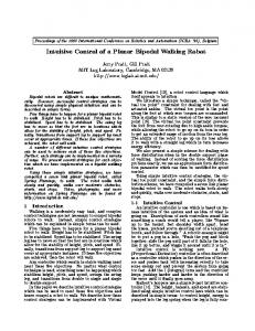
Fig. 1. The IUB rescue robots are teleoperated from a so-called cockpit by a human operator. Despite the human in the loop, they need quite some autonomous functionality ensuring FSG and QoS as the network performance is unknown and can even break completely down, especially as wireless components are involved.
2
The Software Architecture
The IUB rescue robots are teleoperated by humans via standard network technologies (figure 1). The human in the loop ideally feels like being in full control of the system. But the unpredictable performance of networks, in terms of bandwidth, latency, and even reliability, makes it necessary to implement quite some autonomy on the mobile devices. In doing so, there are two major issues, namely ensuring FSG and QoS. FSG must never be violated at any cost. For a mobile robot, this means for example that major obstacles and gaps in the ground must be avoided or that the base must be stopped to avoid serious damages. QoS in contrast defines constraints which maximize utility as long as they are not violated. A timely response to requests from the operator for example ensures that the mobile robot moves along its path as desired. If these constraints are occasionally violated, they should at most cause some slight inconveniences to the operator, but they never must put the whole device or mission at risk.
thread T0: autonomous, hard realtime control
thread T1: semi-autonomous, soft realtime control
thread T2: non-uniform processing
- runs to completion (< 1 msec)
- runs with preemption
- runs with preemption
- consists of sub-threads T0.x
- invokes a dedicated scheduler (B-scheduling)
- services spare-time activities
* scheduled offline
* online scheduling of sub-threads T1.x
* operator changes of mission parameters
* T0.x ensure FSG
* implementing a rich set of behaviors
* building up environment maps
* one sub-thread services the operator
* etc.
* T1.x ensure QoS
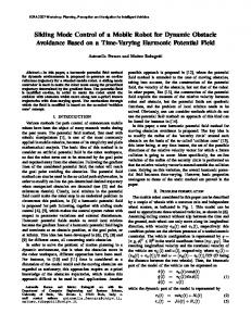
Fig. 2. All threads running on a rescue robot are classified into three types. For each type, a respective master-tread handles the invocation of its related sub-thread. This scheme allows the combined usage of hard realtime, soft realtime, and non-uniform processing.
The main challenge is to find a software architecture which supports these different types of processes. For our rescue robots, we use following approach (figure 2). The run-time system consists of three cyclic master threads T0, T1, and T2 running in timeslots in a 125 Hz major cycle. T0 includes everything dealing with FSQ. It establishes a hard realtime control-system. It is run to completion and its components are scheduled offline. T0 covers the motor- and basic motion-control as well as odometry and positioning. The sub-threads of the master-thread T1 are so-called behaviors. Following the field of behavior-oriented robotics (see e.g. [Bro86,Ste91,Ste94] for an overview), reactive control schemes are used to establish close, dynamic couplings between sensors and motors (see [Bro86,Ste91]) which are computed in pseudo-parallel. Behaviors can be used to keep the robot on a trajectory, to avoid obstacles, to approach a target, to autonomously scan for victims, and so on. The steering commands from the operator are serviced in a dedicated behavior. They are transformed to motion commands and fused with the motion commands from all other behaviors. For the behaviors, soft realtime constraints are the only possible way to go. The “ideal” deadline until when a behaviors has to be handled is in most cases not known as it depends on unpredictable or simply too many conditions. The behaviors are scheduled online by a special so-called B-scheduler (see [BK00]) which is invoked by T1. Note that this scheduler as well as the behaviors are pre-empted by the master-scheduler. The B-scheduler guarantees a idle-free, optimally balanced execution of the behaviors, thus optimizing QoS. Spare time activities, i.e., processes which neither contribute to the FSG nor the QoS, are handled in the master-thread T2. They can include the occasional change of mission parameters by the operator, the construction of environment maps, and so on. 2.1
The hard realtime control
The T0 layer interacts with the higher layers via a shared memory buffer that is written by a thread from a higher layer and is read by the lower-layer T0 thread. The write operation is made atomic by delaying the execution of the T0 thread during write operations. So, target-values in the motion-controller can be asynchronously set by higher level behaviors.
motion control
emergency control
motor control
125 Hz IRQ
update sensor values
update position and orientation
sanity check
update motion errors
active breaking if necessary
compute target speeds
read quadrature decoders update PID errors compute correction values set new pulsewidth
MC68332 onboard TPU A
B
C
D
E
F
PWM
PWM
QDEC 1
QDEC 2
QDEC 1
QDEC 2
Channels:
M
M
Fig. 3. The tasks for realtime control are cyclic processes running at a fixed frequency. Their target-values are asynchronously set by higher level behaviors.
Cockpit PC
Wireless Bridge
Onboard PC
RoboCube
Application Transport Internet Network Data Link Physical Ethernet Internet transmission
Wireless Ethernet
Serial Port Data
Serial Port Inband Handshake
Fig. 4. The flow of the control data from the cockpit to a mobile robot. For certain parts, the time can not be predicted.
The motion-controller so-to-say transforms the target-values on basis of odometric data to appropriate target-values for the motor-control. The motion- and motor-control layers are based on generic software modules for differential drive robots, featuring – – – –
PID-control of wheel speed odometric position- and orientation-tracking rotational and translational trajectory control emergency breaking
As mentioned before, all of the involved subthreads T0.x are scheduled off-line to achieve a hard real-time control. This allows especially to include an emergencymodule which ensures that the robot is stopped if it is for example extremely close to a gap in the ground. This subthread uses active breaking to get the base to a fast, but uncontrolled stop. Hence, the base will be protected in such circumstances from damage, but valuable positioning and trajectory information will be necessarily lost as this harsh breaking will include slipping motions. The option of this subthread is hence explicitly for guaranteeing failure-safety, which only kicks in on extremely rare occasions. Normal obstacle avoidance, including controlled stops which are autonomously activated by the base, are handled on the layer of T1. 2.2
The soft realtime control via behaviors
The hard realtime is needed to ensure FSG. But for tele-operated devices in general, network performance, especially for wireless solutions, can usually not be predicted. Hence, hard realtime conditions are not an option for complete control of the device. Furthermore, hard realtime software is difficult to maintain and to extent. The major trick in our software architecture is that a soft realtime scheduler for behaviors is run as part of the hard realtime schedule. In behavior-oriented robotics, the control of a system is distributed over various processes or behaviors running in virtual parallel. The different behaviors, like controlled obstacle avoidance, ensure a smooth performance of the base. A core behavior, especially from the viewpoint of a teleoperated device, is operator communication, i.e., the transmission of control states from the operator’s console or socalled cockpit to the control hardware (figure 4). To ensure a low-latency operation over the Internet link, a protocol based on UDP packets has been implemented. The protocol is completely stateless. The packets are formed at the cockpit by synchronous evaluation of the control state and transmission to the onboard PC of the mobile platform via Internet. Here, they are received and transmitted to the RoboCube via the serial port. The communication behavior parses the packets and makes its content available to other behaviors via shared memory. Operator command-data for motion is simply fused with the data of other autonomous behaviors. To ensure low-latency-operation, there is no retransmission on lost packets although UDP does not guarantee successful delivery of packets. However, since packets are transmitted synchronously and are only containing state information, there is no need to resend a lost packet since the following packet will contain updated state information. By exploiting this property of the protocol, low-latency operation can be assumed. The communication between the RoboCube and the onboard PC uses inband handshaking to prevent buffer overruns in the RoboCube software. The communication layer software in the RoboCube confirms every packet with a 0x40 control code. Only if this control code has been received, the onboard PC communication layer software transmits the next packet. If the RoboCube communication layer software did not yet confirm a packet when a new packet arrives from the Internet transport layer, this packet is discarded so that the control layer software only receives recent packets, again ensuring low-latency operation.
Moreover, the communication layer measures the time between two packets. Whenever it becomes too large, the command information in the last packet is discarded and the base is transfered into a safe state depending on sensor information, i.e. stopped with the motor controller actively holding the last position. Plausibility checks on the same layer can be used to discard packets or to modify the implications of the information they contain. This is done in a rule-based module. This functionality is optional and allows a convenient incorporation of background knowledge about particular application domains.
cameras sensor moduls mobile base
mobile PC
4x USB−cameras video compression WaveLAN RF−ethernet
CubeSystem
5x Ultrasound Sonar 6x Active Infrared optional (Pyro, Temp., Smoke) Odometry and Positioning Motioncontrol Motorcontrol Battery− and Powermanagement
Fig. 5. A schematic overview of the different components of a rescue robot.
Fig. 6. Left: The RoboCube, an extremely compact embedded computer for robot control. Right: The prototype mobile base of the IUB rescue robots. It is completely constructed from CubeSystem components including the RoboCube as controller, the motor- and sensor-modules, as well as the battery-management hardware.
2.3
The OS support
The control software relies on the RoboCube controller platform, which is shortly described below, and on it’s CubeOS operating system to implement the control application. The CubeOS nanokernel contains real-time multi-threading, abstract communication interfaces and thread control primitives. On top of the nanocore, a set of software drivers provides an application programming interface to the RoboCube’s hardware.
Fig. 7. The new mobile base with six actively driven wheels.
3
The Hardware Implementation of the System
The implementation of the rescue robots is based on the so-called CubeSystem, a kind of construction kit for robotic systems. The center of the CubeSystem is the so-called RoboCube controller hardware (figure 6) based on the MC68332 processor. The compact physical shape of RoboCube is achieved through several techniques. First, boardarea is minimized by using SMD-components. Second, three boards are stacked on each other leading to cubic design, hence its name RoboCube. RoboCube has a open bus architecture which allows to add infinitely many sensor/motorinterfaces (at the price of bandwidth). But for most applications the standard set of interfaces should be more than enough. RoboCubes basic set of ports consists of – – – – – –
24 analog/digital (A/D) converter, 6 digital/analog (D/A) converter, 16 binary Input/Output (binI/O), 5 binary Inputs, 7 timer channels (TPC), and 3 DC-motor controller with quadrature-encoding (QDEC).
The RoboCube is described in more detail in [BKW00,BKW98]. In addition to its central component, the RoboCube as controller hardware, the CubeSystem provides additional hardware, including electronics and mechanics, and software components. In a first prototype, a midsized differential drive was used which is part of the standard CubeSystem componts (figure 6). For the more challenging locomotion tasks that are needed for rescue robots, a new base was developed that features six actively driven wheels (figure 7). The CubeSystem features a special operating system, the CubeOS (see [Ken00]), which ranges from a micro-kernel over drivers to special high-level languages like the process description language PDL (see [Ste92]). The CubeSystem is
used in basic and applied research, industrial projects and academic education. Therefore, a wide range of sensor- and motor-components exists. The CubeSystem also includes dedicated RF-network components. For compatibility reasons, radio-ethernet serviced via a mobile PC is used for our rescue robots. This PC is also used to compute the video-compression. All control and service related data going to and coming from the cockpit is directly relayed from the RF-connection to the RoboCube which handles all service and control related tasks on the rescue robot.
4
Conclusion
The paper described the IUB rescue robots. On its hardware side, the implementation of the robots is based on the CubeSystem, a kind of construction kit for robotic systems. Its use in the design of the rescue robots is shortly presented in this paper. The main focus of this paper is on the general problem of ensuring secure but convenient control of a tele-operated device. We presented a special software architecture which incorporates Quality of Service (QoS) and Fail-Safe Guarantees (FSG). The main idea of the architecture is to find a suited way to combine hard and soft realtime scheduling. Concretely, we use an hierarchical scheduling structure as follows. On the highest layer, there are only three threads T0, T1, T2 running in time-slots in a fixed frequency master cycle. T0 is run to completion and its subthreads T0.x establish a hard realtime control, ensuring FSG. The thread T1, which can be preempted, invokes a further softrealtime scheduler for behaviors, which provide QoS. The behaviors establish close, dynamic couplings between sensors and motors computed in pseudo-parallel. This includes the steering-commands from the human in the loop, which are simply fused with the autonomous functionalities. The third thread T2 allows optional non-uniform processing, e.g., for operator changes of mission parameters.
References [BK00]
Andreas Birk and Holger Kenn. Programming with behavior-processes. In 8th International Symposium on Intelligent Robotic Systems, SIRS’00. 2000. [BKW98] Andreas Birk, Holger Kenn, and Thomas Walle. RoboCube: an “universal” “specialpurpose” hardware for the RoboCup small robots league. In 4th International Symposium on Distributed Autonomous Robotic Systems. Springer, 1998. [BKW00] Andreas Birk, Holger Kenn, and Thomas Walle. On-board control in the RoboCup small robots league. Advanced Robotics Journal, 14(1):27 – 36, 2000. [Bro86] R.A. Brooks. A robust layered control systems for mobile robot. IEEE Journal of Robotics and Automation, RA-2(1):14–23, 1986. [Ken00] Holger Kenn. CubeOS, The Manual. Vrije Universiteit Brussel, AI-Laboratory, 2000. [MCM01] Robin R. Murphy, Jenn Casper, and Mark Micire. Potential tasks and research issues for mobile robots in robocup rescue. In Peter Stone, Tucker Balch, and Gerhard Kraetszchmar, editors, RoboCup-2000: Robot Soccer World Cup IV, volume 2019 of Lecture notes in Artificial Intelligence (LNAI), pages 339–334. Springer Verlag, 2001. [Sny01] Rosalyn Graham Snyder. Robots assist in search and rescue efforts at wtc. IEEE Robotics and Automation Magazine, 8(4):26–28, 2001.
[Ste91]
[Ste92] [Ste94]
Luc Steels. Towards a theory of emergent functionality. In Jean-Arcady Meyer and Steward W. Wilson, editors, From Animals to Animats. Proc. of the First International Conference on Simulation of Adaptive Behavior. The MIT Press/Bradford Books, Cambridge, 1991. Luc Steels. The PDL reference manual. Vrije Universiteit Brussel, AI-Laboratory, 1992. Luc Steels. The artificial life roots of artificial intelligence. Artificial Life Journal, 1(1), 1994.