visual search pattern (right) matchbox red car police car red car matchbox police car. Fig. 3. Object map during system trial, objects represented by colour-.
A Research Platform for Embodied Visual Object Recognition ∗ Department
Marcus Wallenberg ∗ , Per-Erik Forss´en∗ of Electrical Engineering, Link¨oping University, Sweden Email: {wallenberg,perfo}@isy.liu.se
Abstract—We present in this paper a research platform for development and evaluation of embodied visual object recognition strategies. The platform uses a stereoscopic peripheral-foveal camera system and a fast pan-tilt unit to perform saliency-based visual search. This is combined with a classification framework based on the bag-of-features paradigm with the aim of targeting, classifying and recognising objects. Interaction with the system is done via typed commands and speech synthesis. We also report the current classification performance of the system.
I. I NTRODUCTION Recently, there has been an increased interest in visual object recognition in the embodied setting. One reason for this is developments in interactive robotics for general purpose assistance tasks. Such tasks often require the ability to recognise objects from textual, oral or otherwise abstract description. Object recognition could also benefit many other applications. Image retrieval, classification and recognition have been studied extensively in the case of matching and indexing in large image databases [1]–[5], and the methods used are closely related to those employed by us. Embodied visual object recognition, however, introduces a “here and now” aspect not present in the database case. As a result of this, object recognition is not a oneshot phenomenon, but rather an active, ongoing process involving visual search, decision-making, adaptation and learning. In this paper we present the hardware and software platform, upon which we intend to further develop and evaluate such mechanisms. A. Motivation Our aim is to study the cycle of attention, foveation, and decision that forms the core of all embodied recognition systems. In particular, we are interested in trying out ideas inspired by the human vision system, as the human visual system is one of the most successful embodied recognition systems. Human visual search is performed using a peripheralfoveal system, using low-acuity peripheral vision for guidance, and high-acuity foveal vision for recognition. Foveal vision is directed by fast eye movements known as saccades, which orient the eye toward regions of interest in the visual field. For peripheral vision, something akin to visual saliency [6], [7], is used to guide attention. Pattern matching in the human brain is very rapid. From neuroscience we know that the first stage of foveate object
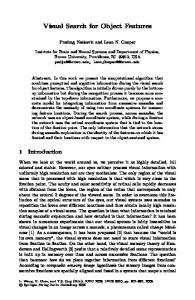
Fig. 1.
Robot platform (left)
recognition happens in less than 150ms [8]. This implies that the processing has to be mainly feed-forward. The processing hierarchy starts with only a few feature types (oriented bars and edges) and a high spatial specificity, but for each layer the number of feature types increases, and the spatial specificity is reduced. This standard model [9], and variants thereof have been implemented and used in computer vision with some success [10]. In this paper, we will employ a more crude (but much faster) technique known as bag-of-features [11], [12]. Interestingly, bag-of-features can be seen as an equivalent to using only the top level of the standard model hierarchy. B. The Bag-of-features Paradigm Local invariant features such as SIFT [13] and MSER [14], consist of a detection and a description step. The detection step extracts local image patches in reference frames that follow the local image structure. In the description step, the local image patch is converted into a descriptor vector that is robust to illumination changes and perturbations of the reference frame. Bag-of-features (BoF) is a collective name for techniques that use local invariant features to build descriptors for entire images, by first quantising them into visual words and then computing histograms of visual word occurrences. II. S YSTEM OVERVIEW The aim of this work is to create a platform upon which methods for embodied visual object recognition
can be developed and evaluated. This platform should be easy to use, yet capable of the required vision tasks. It should also allow for relatively easy implementation and evaluation of different methods and algorithms, while (to some degree) allowing the developers to disregard common issues associated with robotics and automatic control. A. Hardware The robot platform constructed (dubbed “Eddie – the Embodied”) consists of a dual camera mount atop a rigid aluminium frame. The frame is in turn mounted on a fast pan-tilt unit (see figure 1). The cameras used are the Flea2 [15] model from Point Grey Research. The pan-tilt unit is a model PTU-D46-17.5 [16] from Directed Perception. The robot also has an on-board speaker system for communication. The system is controlled by a desktop computer via FireWire and USB. B. Command, Control and Communication Since the system is designed to perform both interactively guided and autonomous tasks, mechanisms for command, control and user communication have been implemented. In the current implementation, user commands are issued by typed instructions, providing commands and feedback when needed. The system communicates with the user by displaying images and text on a monitor, and through speech synthesis using the eSpeak text-to-speech engine [17]. Internal state management and control flow is achieved through object-oriented implementation of the system software as a cognitive agent capable of carrying out target acquisition and classification tasks and which contains internal structures for storing previous actions and observations. C. Visual Attention A mechanism for visual attention is vital to any artificial cognitive system which seeks to detect, locate and target potentially “interesting” objects in view under time constraints. The system uses a low-acuity peripheral view combined with a high-acuity foveal view to implement visual search and target sampling. In the current implementation this is achieved by a combination of a static visual saliency measure and an inhibition mechanism which suppresses visual saliency in regions containing previous object observations. The saliency measure used is the incremental coding length (ICL) [7], which is calculated for all peripheral views captured by the system. The result of such visual search behaviour is illustrated in figure 2. D. Target Acquisition Target acquisition is performed by thresholding the modified saliency map described in section II-C to find regions of high visual saliency that have not yet been examined. A region of interest (ROI) is fitted to contain the corresponding region in the left peripheral view. This region is then matched to the right peripheral view using block-matching combined with a KLT tracker [18].
Fig. 2. Image (left), resulting (thresholded) saliency map and resulting visual search pattern (right)
red car
red car
matchbox police car
matchbox police car
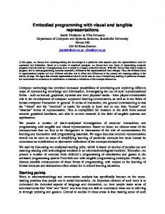
Fig. 3. Object map during system trial, objects represented by colourcoded convex hull vertices in the image plane (left view, right view)
Once target position has been established in both views, a prediction of the required centering saccade is calculated using a manually calibrated linear parametric model. This centering saccade is then executed, with the aim of centering the target region in both the left and right view. High-resolution patches of the target regions are then captured. Vergence is achieved through offset sampling in the images. E. Object Classification and Recognition In the current implementation, a fixed number (typically one to five) of high-resolution ROI pairs (left and right) can be captured. If more than one pair is captured, the system changes the camera position slightly between captures and then combines all features extracted from all the images pairs into a single set (thus “throwing” all the features into one “bag”). This set is then classified according to the procedure described in section III-C. F. Object Representation and Permanence In order to keep track of previous object sightings, object observations are stored by the system as (nonmetric) 3D point clouds of matched feature locations and their associated class labels. This representation is useful when performing visual search because it allows the system to keep track of all previously spotted objects even when they are not currently in view. The object representation can be visualised by projecting the convex hull of the stored point cloud to the image plane and superimposing it on the corresponding peripheral view as shown in figure 3. III. C LASSIFICATION AND R ECOGNITION Bag-of-features methods rely on matching histograms of visual word occurences. Their use requires the construction of a visual vocabulary, templates to match samples to (referred to here as prototypes) and one or several
matching criteria corresponding to some measure of similarity. The methods used in the current implementation to create these are described in this section. A. Feature Extraction and Vocabulary Generation In order to create a visual vocabulary, features must be extracted from some set of images, and then clustered to provide a vocabulary for sample quantisation (see section I-B). The choice of vocabulary, as well as its size, affects classification performance, and should ideally be tailored to fit the data the system will encounter. In the practical case however, this is not possible. The current aim is therefore to fit the vocabulary to the available training data. To create the vocabulary, SIFT features are computed for all training images. A subset of approximately 105 of these is then selected and clustered using k-means, where k = 8000. This choice is made due to memory constraints in the current implementation. The resulting visual vocabulary is used to quantise all features extracted from the training images and then create visual word histograms for prototype generation (see section III-B). B. Prototype construction In order to match novel samples to the database, templates or prototypes must be created. The aim is to create a descriptive representation of training data, which is also suitable for matching. The method of prototype construction used is subject to a tradeoff between high matching speed, requiring a very compact representation, and the descriptive power of the prototype set. Also, the specificity of the prototypes must be weighed against their ability to generalise to novel images of known objects. Additionally, it seems that different classification methods are affected differently by these choices. The two methods used here represent opposite extremes of the prototype construction spectrum, and are in turn suitable for two different classification methods (see section IV-B). The first (used in nearest class mean (NCM) classification, see section III-C) combines all visual word histograms obtained from training images of a particular object into a single histogram by componentwise summation, so that X pjk = tnk . (1) n
Here, pjk are the elements of the prototype vector pj describing object class l, and tnk are the elements of word histogram tn obtained from a sample image of the same object class. A single and unique class label Cl is then associated with pj . The second method (used in k-nearest neighbours classification, see section III-C) treats all tn as unique instances, thus in essence setting pj = tn but instead allows multiple assignments of class labels, so that several pj are associated with the same Cl . In addition to this, a weighting scheme based on the inverse document frequency (IDF) [19], [20] is computed.
This assigns a weight wk to each histogram bin in the visual word histogram, where ! N , (2) wk = − ln P n:tnk >0 1 and N is the total number of training samples (for all classes). In order to facilitate fast and efficient matching (as described in section III-C), these weights are then applied to the elements of all pj , which are then normalised to Euclidean unit length and stacked into a matching matrix P = {pˆw 1 , . . . , pˆw j }.
(3)
C. Classification of Novel Images Multiple observations of the same object tend to increase the likelihood of feature detection (see section IV-B). If multiple ROI pairs are available (see section II-E), the concatenated set of all extracted features is used. The resulting set of features is then converted into a query vector, q, containing the visual word histogram of the feature set. Similarity, s, is calculated as the Tanimoto coefficient [21] of the weighted query and prototype vectors, so that sj =
q T W 2 pj , ||W q|| · ||W pj ||
(4)
where W is a diagonal matrix, containing the weights wk . By applying the element-wise weighting and normalˆ w , s can be isation to q, creating a new query vector q calculated as ˆ Tw P . s=q
(5)
Using these similarities the sample is classified. In nearest class mean (NCM) classification, the query is associated with the class label Cl corresponding to the prototype pj having the largest sj . In k-nearest neighbour classification, we instead perform voting among the k largest elements of s and their corresponding Cl . D. Embodied Object Recognition It is important in this case to make a distinction between classification and recognition. Classification assigns an object to a known category, while recognition requires the system to handle objects which do not correspond to any known category. Thus, for each act of classification, a measure of certainty must be assigned in order to distinguish between • the correct assignment of a known class label to a known, previously observed object • the incorrect assignment of a known class label to an unknown object • the re-detection of a previously observed, but as of yet unlabeled object. Several such measures and mechanisms for their utilisation are currently under investigation.
CCR (one pair, LOOCV) CCR (five pairs, LOOCV) CCR (one pair, “easy” set) CCR (one pair, “hard” set) CCR (five pairs, “easy” set) CCR (five pairs, “hard” set)
NCM 1.000 1.000 0.985 0.883 0.994 0.922
KNN 0.997 1.000 0.991 0.943 1.000 0.972
TABLE I C ORRECT C LASSIFICATION R ATE (CCR) IN LOOCV AND ON THE EVALUATION SETS USING NEAREST CLASS MEAN (NCM) AND k NEAREST NEIGHBOURS (KNN) CLASSIFICATION WITH k = 50
IV. R ESULTS The results in this section are divided into two categories. The first deals with evaluation of the prototype set, and the second with the classification ability of the system. In order to find out how more views would influence classification performance, the training and evaluation sets were structured so that they contained sequences of five image pairs depicting the same object pose from slightly different camera positions. These were then treated as a single multi-view observation in the “five pairs” cases shown in table I. A. Prototype Evaluation Since a good prototype set is crucial in achieving high classification performance, the ability of the prototype set to correctly classify samples drawn from the same samples used to create it was evaluated using leave-oneout cross-validation (LOOCV) [22]. The procedure used is as follows. For each training sample tn , the corresponding prototype vector pk and the weights wj are recalculated, disregarding contributions from tn . The classifier is then queried using the sample removed. In the multi-view case, the LOOCV procedure was modified to disregard all samples associated with a specific object pose. Results are shown in table I. B. Classification Performance Classification performance was evaluated on two dedicated evaluation sets of image pairs. An “easy” set, collected under conditions similar to the training set; and a “hard” set collected using a changing background, different lighting and varying target distance. Examples from the different sets are shown in figure 4. Results are listed in table I. V. C ONCLUSIONS AND F UTURE W ORK We have implemented a platform for the study of embodied visual object recognition. The system is capable of targeting and classifying objects viewed, and communicating this to a person. Planned future developments of the platform include incorporating a linear drive for lateral translation, the investigation of new features for use in matching, and the incorporation of geometric constraints for improved classification and recognition performance. Another important task is the investigation of adaptive sequential recognition strategies.
Fig. 4. Examples of training and evaluation images. Rows top to bottom show images from: training set, “easy” and “hard” evaluation sets.
ACKNOWLEDGEMENT This work was supported by Link¨oping University, and the Swedish Research Council through a grant for the project Embodied Visual Object Recognition. R EFERENCES [1] D. Nist´er and H. Stew´enius, “Scalable recognition with a vocabulary tree,” in CVPR, vol. 2, 2006, pp. 2161–2168. [2] R. Fergus, L. Fei-Fei, P. Perona, and A. Zisserman, “Learning object categories from Google’s image search.” in ICCV, vol. 2, 2005, pp. 1816–1823. [3] L. Fei-Fei, R. Fergus, and P. Perona, “One-shot learning of object categories,” IEEE TPAMI, vol. 28, no. 4, pp. 594–611, 2006. [4] S. Savarese and L. Fei-Fei, “3D generic object categorization, localization and pose estimation,” in ICCV, 2007. [5] H. J´egou, M. Douze, and C. Schmid, “Hamming embedding and weak geometric consistency for large scale image search,” in ECCV, ser. LNCS, vol. I, 2008, pp. 304–317. [6] L. Itti, C. Koch, and E. Niebur, “A model of saliency-based visual attention for rapid scene analysis,” IEEE TPAMI, vol. 20, no. 11, pp. 1254–1259, 1998. [7] X. Hou and L. Zhang, “Dynamic visual attention: Searching for coding length increments,” in NIPS, 2008. [8] S. Thorpe, D. Fize, and C. Marlot, “Speed of processing in the human visual system,” Nature, vol. 381, pp. 520–522, 1996. [9] M. Riesehuber and T. Poggio, “Hierarchical models of object recognition in cortex,” Nature Neuroscience, vol. 2, no. 11, pp. 1019–1025, 1999. [10] J. Mutch and D. G. Lowe, “Multiclass object recognition with sparse, localized features,” in CVPR, New York, 2006, pp. 11–18. [11] J. Sivic and A. Zisserman, “Video google: A text retrieval approach to object matching in videos,” in ICCV, 2003, pp. 1470–1477. [12] G. Csurka, C. R. Dance, L. Fan, J. Willamowski, and C. Bray, “Visual categorization with bags of keypoints,” in Workshop on Statistical Learning for Computer Vision, 2004. [13] D. G. Lowe, “Distinctive image features from scale-invariant keypoints,” IJCV, vol. 60, no. 2, pp. 91–110, 2004. [14] S. Obdrz´alek and J. Matas, “Object recognition using local affine frames on distinguished regions,” in BMVC, 2002, pp. 113–122. [15] “Flea 2 technical reference manual,” 2006, Point Grey Research. [16] “Pan-tilt unit (model ptu-d46) user’s manual, v2.14.0,” 2006, Directed Perception Inc. [17] Website: http://espeak.sourceforge.net. [18] J. Shi and C. Tomasi, “Good features to track,” in CVPR94, Seattle, June 1994. [19] K. S. Jones, “A statistical interpretation of term specificity and its application in retrieval,” Journal of Documentation, vol. 28, pp. 11–21, 1972. [20] G. Salton and C. Buckley, “Term-weighting approaches in automatic text retrieval,” Information Processing and Management, vol. 24, pp. 513–523, 1988. [21] T. T. Tanimoto, “IBM internal report,” 1957. [22] C. Atkeson, “Using locally weighted regression for robot learning,” in ICRA, Sacramento, CA, 1991, pp. 958–963.