building automation domain a specific system is de- livered only once. ... scription of the requirements of the system to be de- veloped. ..... SFB 501 Report 2/99.
A Reuse- and Prototyping-based Approach for the Specification of Building Automation Systems Andreas Metzger, Stefan Queins AG VLSI Design and Architecture, Department of Computer Science University of Kaiserslautern, Germany {metzger, queins}@informatik.uni-kl.de
Abstract In this paper an efficient requirements engineering approach that is specialized towards the domain of building automation systems is presented. This approach bases on the application of object-orientation to handle complexity, reuse to gain efficiency and product quality, and prototyping to enable validation early in the development process.
1 Introduction The development process of embedded real-time systems differs from that of other applications in many ways. One difference is due to the small number of identical systems that are created. Especially in the building automation domain a specific system is delivered only once. Another difference lies in the fact that the life cycle of these systems is relatively long. Therefore, the development process needs to be very efficient and traceability has to be established during the whole life cycle, which includes development as well as maintenance after installation. A further property of building automation systems that has to be dealt with during development is the complexity that results from the integration of control strategies for different physical effects, e.g. light and temperature. This integration is required because of the physical coupling of these effects. Additionally, the complexity stems from the large number of objects that have to be regarded, e.g. sensors and actuators. In this paper, we focus on the first phase of the development process, the requirements engineering phase. In this phase the often-vague needs of the customer have to be transformed into formal system requirements, which have to be consistent and complete. Complete in this context means that there are no needs that are not reflected in the system requirements. To gain efficiency in performing this step, the development process is specialized towards a specific domain. This specialization allows us to define the process by describing the different process parts and development products in a very fine-grained manner, and also provides the precise definition of guidelines for each process part.
Our method for the requirements analysis process relies on the application of three basic techniques: object-orientation, reuse, and prototyping. Object-orientation is employed to handle the large number of objects. Reuse allows the reduction of effort mainly by producing products of high quality, and is supported by a precise definition of dependencies between development products. Prototyping permits the early validation of the system together with customers as well as the verification of single development decisions by developers. An efficient prototype creation is established through prototype generation from models. The specialization towards a specific domain, the availability of reuse and the ability to do prototyping leads to an efficient requirements engineering process that produces a formal, complete, and consistent description of the requirements of the system to be developed. The applicability of the method was demonstrated in several case studies. 2 Definition of the Method The description of a software development method can be structured into the definition of several interrelated aspects in a natural way. A suitable notation is chosen for modelling each of these aspects. We have described our method using the following models. •
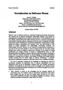
Product Model: It describes the structure of and the relations between all products that are produced during the development. We introduce the notion of artifacts, that can roughly be identified with development products. With regard to the definition of the process model, artifacts are hierarchically defined (Fig. 1). They are specialized to atomic artifacts, called features, and more complex artifacts, called configurations, which
are composed of less complex artifacts. The documents are special configurations, on which the developers work. In addition, the definition of versioning for each artifact is part of this model. The traceability between different artifacts is also given. We have used UML class diagrams [BJR99] to define the product model.
•
Strategy Model: This model describes, at which point of the development a certain feature should be edited. By defining such a strategy model, the constraints, expressed in the process model, are refined, which appropriately reduces the flexibility of the developers. There are two well known styles of this limitation. One style is the strictly defined phase model, where each process step relates to a specific phase and the whole project may only be in one phase at the same time. The other is a workflow-oriented style, where the process steps are assigned to workflows, which can be executed simultaneously. To assess the progress of development for the latter style, coarse-grained phases are introduced. They correlate to the workflows as they are finished, when the largest amount of the work of the respective workflow has been done. Because such a strategy model is a refinement of the process model, the notation is an extension of the notation used for the process model.
•
Project Environment Model: All additional aspects that are relevant during the development are described in this model. These are, for example, the tools, especially their interfaces, data models for gathering development effort, or the different persons and their roles.
artifact
feature
configuration
document
Fig. 1: Product Classification •
Process Model: The task of requirements engineering is divided into several, less complex subtasks, called process steps. These process steps work on documents and they are composed of atomic activities, by which only one feature is edited. This leads to a hierarchical definition of the process model. The process steps imply restrictions on the sequence of development activities, because documents act as essential inputs of process steps. Further, a single development decision consists of the execution of a process step with the application of certain criteria, which can differ for different development phases. During the requirements engineering phase the overall criterion besides completeness is the clarity of the individual development decision. The process model is written in an extension of Petri nets [Bre92], which allows describing the parallelism that arises during development.
BuildingDescription
objectStructureSpecification
ObjectStructure ObjectStructure Specification
Requirements Specification
Requirements Description requirementsDescription
ObjectType
requirementsModeling
SDLBlockType
To illustrate our method, an informal description of the process model is shown in Fig. 2 together with the most relevant documents. Furthermore, the assignment of the process steps to workflows is shown. However, the figure can only give an overview, because not all the products are depicted and the process steps are shown at a fixed level of abstraction. The starting point of the requirement engineering process is the description of the problem that is divided into needs and the building description. The needs
Needs
Testcases
document
inspection
process step
taskDescription
input/output
TaskList
developTestCase inspection Testcases C hecking
prototyping
Fig. 2: Overview of the Development Process
informally describe the requirements from the point of view of the customer. They have to be split into tasks that collectively realize all needs. The main difference between tasks and needs is, that a task has to be assignable to one object type. These object types form the structure of the system, described in object structure, in which only a strict aggregation hierarchy is allowed. The object structure is a refinement of the building structure, which is part of the building description. After these two process steps, the object types and their main tasks have been elicited. In the next process step these object types have to be described in a more detailed manner by defining how the tasks should be solved. This informal description includes the structure and the behavior of the respective object type. Then, each object type has to be transformed into a formal specification. We have chosen SDL [OFM97] as the specification language, where the structure is represented by a block hierarchy and the behavior is expressed by extended finite state machines. Besides a possibility to inspect each document for the verification of a process step, we have to develop test cases, against which a prototype of the SDL models is tested (see Section 4). Further, this prototype is helpful in checking the system behavior together with the customer. To be able to generate prototypes in early development phases requires executing process steps that in other development methods can be regarded as only belonging to subsequent phases. We will execute these process steps in later phases again, but as mentioned before, with the application of different criteria. As an example, we determine the structure of the system in the requirements engineering phase by using the aspects of clarity and simplicity. The output of this process step is a structure model, which has to be restructured in the design phase by taking a desired distribution of the system into account. Taking these considerations into account, at the end of the requirements engineering phase, its output product can be regarded as the system requirements as well as a first version of the output of the design phase. But at this point of development, no specific design decisions have influenced the respective product. We want to support each process step, or—in more detail—each activity by introducing reuse. Different kinds of reuse and some considerations on the gain of effort that is achieved through reuse are mentioned in the following section. 3 Reuse Reuse is an important technique to get high quality products in short time. However, not every artifact that seems to be a suitable candidate for reuse, reduces the development time. Even if the application of re-
use would lead to artifacts of higher quality, the effort to adapt a single artifact can be greater than the effort to develop it from scratch with the same level of quality. Concerning the whole project, this implies that the application of reuse, might not lead to a gain of effort in every case. To evaluate if reuse leads to benefits, we need to gather experience with reuse. Therefore, we allow access to all products that were developed in earlier processes. This is called external reuse. The granularity of these reuse artifacts ranges from the small features up to complex configurations like the system requirements. All reuse artifacts are accessible via a so called dictionary, which allows searching for artifacts by using the intuitive structure of the underlying building model. Further, all the domain knowledge that was not packaged in a reusable artifact, resides in the dictionary. Because reuse naturally appears within a complex project, the reuse of artifacts, which are developed in the respective project should be supported. This second kind of reuse is known as internal reuse. In evaluating the benefits of reuse, a first step is to determine the effect of reuse on the whole project. After a project has finished, this can be done by quantifying the gain of productivity that was caused by reuse only. For that we have adapted a metric, given in [FrT96], to measure the relative productivity P rel , which is specified in relation to the productivity of a project without reuse and regards the internal as well as the external reuse. P rel is given by 1 ⁄ E rel . Assuming that the absolute development effort of an artifact correlates to its complexity, E rel can be computed by the weighted average 1 E rel = ------------- ⋅ ∑ K a ⋅ E rel,a , ∑ Ka a a
where K a defines the complexity of artifact a , and E rel,a is the relative development effort of artifact a , which is determined in relation to the effort without reuse. The complexities are recursively defined according to the construction of the products. So, after the complexities for the features have been determined, the complexities for the more complex products can be calculated. As an example, the complexity of an informal description of a task is within the range from 0 to 5. Then, the complexity of the informal description of one object type is computed by the sum of all its tasks. The complexity of the respective SDL specification of object type ot is given by inf + n , = 3 ⋅ K ot K oSDL t
where K oinft is the complexity of the informal description and n is the number of components of the object
type. For the relative effort E rel,a for artifact a , we use a formula, in which R a specifies what amount of artifact a is developed with reuse, and E rel,int is the relative effort of the reuse activities for integrating the reusable artifacts into artifact a : E rel,a = R a ⋅ E rel,int + ( 1 – R a ) ⋅ 1 . The relative integration cost E rel,int is computed by the relation between the adaption effort E adapt and the creation effort E cre : E rel,int = E adapt ⁄ E cre . If a reuse operation was performed, the measured adaption effort and the estimated creation effort have to be used, and vice versa. To increase the confidence in the formulas, the following example shows their application. We assume that we have three object types A, B, and C (see Fig. 3), which make up the whole system and act as artifacts in the formulas. A:
R A = 0.5
SDL = 8 KA
B:
R B = 0.25
K BSDL = 6
C:
R C = 0.5
K CSDL = 4
Fig. 3: Example of three object types For the shaded fraction of object type A, we assume a reuse operation with E rel,int = 0.5. The relative effort for the remaining fraction is 1, because no reuse is applied. The relative cost for A is computed by using the given fraction R A to E rel,A = 0.75. To compute the relative productivity of the whole project, we further assume that E rel,B = 0.5 and E rel,C = 0.2. Taken the given complexities into account, the relative project cost can be computed and thus the relative productivity caused by reuse only is 1.83. An open question is how to precisely estimate the values for the correct prediction, if a particular reuse operation leads to a benefit or not. This is where reuse of earlier reuse results can help to make such estimations. 4 Prototyping In addition to the application of reuse, prototyping, when applied during requirements analysis, exposes several benefits. First, it allows verification through testing by the system engineer. Second, and more important, it provides an early validation of the system by the customer. This reduces misunderstandings and
errors and thereupon leads to higher product quality. To benefit from prototyping in the context of an efficient development process, the construction of prototypes must be possible with little effort. In our approach this requirement is realized by generating prototypes from models, which additionally guarantees consistency between the models and the prototypes. To allow prototyping as early as possible, incomplete models that are predominant until late in the requirements analysis phase must suffice as input for prototype generation. This problem is solved by initially partitioning the incomplete model into model partitions. Then, missing or incomplete model partitions are replaced by stubs that can be derived from models of a higher level of abstraction, e.g. the object structure. Finally, all model partitions are composed to a single model from which a prototype can be generated. Because a building automation system and the controlled environment are tightly coupled, prototyping of such a system can produce reasonable results only if the prototype and the environment are interlinked. The environment can be realized by building simulators, the physical building, or a mixture of both. Simulators offer a greater flexibility over the physical environment because they can easily be modified and are independent of external influences, like time of day or weather. Furthermore, they remain the only choice as long as the physical installation does not exist. As the development proceeds, prototyping within the physical building becomes necessary, because certain properties of the system cannot be evaluated using simulators. A good example is lighting control, as it is difficult—if not impossible— to decide on a correct comfort lighting level by the mere reading of a value like 100 Lux. To allow the flexible and effortless interlinking of prototypes and the different realizations of the environment that are depicted above, standardized interfaces are established. Currently, we support prototype generation from SDL-models using Telelogic’s SDT C-code generator [Sta01]. Depending on the purpose of prototyping, the developer can choose from target platforms ranging from large scale workstations running UNIX or Windows to small embedded PCs running QNX [QNX01]. During generation, the SDL-models are augmented with SDL-fragments and C-code that realize the interface to the environment on the basis of TCP/IP sockets [Rag93]. Additionally, interchangeable Java components are used for adapting to different prototype and environment configurations [Met99]. Fig. 4 shows how the above concepts are reflected in our prototyping environment. This environment can further be used to produce traces that contain the propagation of signals, the expiration of timers, the
ing and lighting control components. Further, explicit reuse was introduced and the process was improved by utilizing the experience of former projects.
SDL Model
Partitioning N
Prototyping Environment
O435
SDL Model Partition O433 CL426
hw
1
O429
section1
O431
Composition O424
SDL Model
M427 CL422
Generation O425 P420 O423
Prototype Trace
O421
CL418
hw
O419
1
Interlinking
section2
Prototype Partition
O416
O417 O414 O415 O412
Building Simulator
Physical Building
P413
5 Case Study In this section, we want to present one case study in detail. It was performed by a team of seven developers and one team leader, who acted as a developer, too. This case study, denoted as CS3/2 [QuZ99], is the successor of the baseline CS3/1 [FMQ99]. In CS3/1, the assignment was to develop a lighting control system for a floor of a building at the University of Kaiserslautern. This floor, which is separated into three sections, consists of 25 rooms of different types, which are connected by a hallway (Fig. 5). For CS3/2 the problem was extended by adding a heating control component, which resulted in some conflicts concerning actuators that need to be controlled by both heat-
CL411
CL410
section3
invocation of methods, and the interaction with the environment. The system’s dynamic behavior can automatically be analyzed using these traces [QST99] leading to results that can either provide feedback for requirements analysis or support development decisions during system design. In addition to providing data for design decisions, our prototyping technique can be extended to the design phase, where distributed prototypes become necessary for verification and validation. As model partitioning is already available, a distributed prototype can be created by the composition of prototype partitions that in turn can be generated from model partitions.
hw1
Fig. 4: The Prototyping Environment
Fig. 5: Floor Plan The description of the problem for CS3/2 consisted of 68 different needs and a description of the building, which includes the installation of sensors and actuators. To get an impression, a typical need is depicted: “Shortly before a persons enters a hallway section, the light should be turned on, if neccessary.” All needs were split into 126 different tasks, which were assigned to 37 object types, which were instantiated to 920 instances. The total effort was 26,000 minutes, which is equivalent to approximately ten man weeks. As Fig. 6 shows, the most effort was spent on the formal specification, which is the transformation from the informal object type description to SDL models. The checking of the products was done by inspection and prototyping. The effort of approximately ten minutes for generating each prototype is included in the effort of the workflow Checking as well as the development of 42 test cases. A link to all development products can be found at: http://wwwagz.informatik.uni-kl.de/projects.
Effort [min]
CS3/1
CS3/2
ObjectStructure Specification
10000 8000 6000 4000 2000 0
Workflow
100
25
80
20
60
15
40
10
20
5
0
0 Phase
3
4
effort of removal [min]
number of errors
Besides the development effort, the number of errors, the phase of occurrence, which is closely related to the time of occurrence, and the effort to remove an error are characteristic properties of a project and its development method. The distribution of errors and the removal effort relating to the different phases is shown in Fig 7.
2
25
37
total complexity [units]
688
1826
19000
26000
effort per complexity unit
27.6
14.2
total relative productivity P rel
1
1.94
6..58
9..114
range of relative effort per artifact E rel,a
1
0.44..1.35
relative productivity P rel caused by reuse
1
1.22
range of complexity K a [units]
Fig. 6: Distribution of Effort
1
number of object types
total effort [min] Checking
12000
Requirements Specification
Requirements Description
14000
Fig. 7: Distribution of Errors and their Removal Effort To determine the productivity, the project results were set in relation to the predecessor project CS3/1. Besides the development effort, the range of some interesting values for one type of artifacts, the SDL object types, are shown in Table 1. We have computed a relative productivity of 1.94, where the introduction of reuse caused a factor of 1.22. The difference between these two values is caused by an improvement of the process in addition to the introduction of reuse. This productivity of reuse is smaller than that what can be expected from literature that evaluates the gain of effort caused by reuse (e.g. [FrT96] and [McC97]). Therefore, subsequent and precise inspections of the particular reuse operations are necessary. Further, a correlation between the estimated complexity and the development effort of the artifacts has been shown. The correlation factor, computed according to Bravais Pearson, is 0.87.
Table 1: Summary CS3/1 and CS3/2 The resulting requirements specification of the control system was used in a subsequent design step and a distributed prototype was installed in the physical building [Met01] to support this development step. References [BJR99] G. Booch, I. Jacobson, J. Rumbaugh. The Unified Modelling Language User Guide. Addison Wesley Longman. Reading, MA. 1999 [Bre92] F. Bretschneider. A Process Model for Design Flow Management and Planning. Ph.D Thesis. Dept. of Computer Science. University of Kaiserslautern. 1992 [FMQ99] R. Feldmann, J. Münch, S. Queins, et al. Baselining a Domain-Specific Software Development Process. SFB 501 Report 2/99. University of Kaiserslautern. 1999 [FrT96] W. Frakes, C. Terry. Software Reuse: Metrics and Models. ACM Computing Surveys. Vol. 28, No. 2. 1996. 415–435 [McC97] C. McClure. Software Reuse Techniques: Adding Reuse to the System Development Process. Prentice-Hall PTR. Upper Saddle River, NJ. 1997 [Met99] A. Metzger. An Interlink of Building Control System Prototypes and the Lighting Simulation Lumina. Report 8/99. University of Kaiserslautern. 1999 [Met01] A. Metzger. Ein flexibles Testfeld für Experimente im Bereich der Gebäudeautomation und simulation. SFB 501 Report 4/01. University of Kaiserslautern. 2001
[OFM97] A. Olsen, O. Færgemand, B. Møller-Pedersen, et al. System Engineering Using SDL-92. 4th Edition. North Holland. Amsterdam. 1997 [QNX01] QNX System Architecture. Online Document. QNX Software Systems. 2001 http://www.qnx.com/literature/qnx_sysarch/ index.html [QST99] S. Queins, B. Schürmann, T. Tetteroo. Bewertung des dynamischen Verhaltens von SDLModellen. SFB 501 Report 9/99. University of Kaiserslautern. 1999 [QuZ99] S. Queins, G. Zimmermann. A First Iteration of a Reuse-Driven, Domain-Specific System Requirements Analysis Process. SFB 501 Report 13/99. University of Kaiserslautern. 1999 [Rag93] S. Rago. UNIX System V Network Programming. Addison-Wesley Publishing Co. New York, NY. 1993 [Sta01] R. Stamvik. Integrating SDT generated code with target platforms. Technical Paper. Telelogic AB. 2001 http://www.telelogic.se/download/papers/integtarget.pdf