Table I: Experimental results for some commonly used image. Original image. Capacity [bits] PSNR [dB] elaine.tiff (512x512). 2462. 50.5132 boat.tiff (512x512).
E. Varsaki, V. Fotopoulos, A. N. Skodras, ‘A reversible data hiding technique embedding in the image histogram’
A reversible data hiding technique embedding in the image histogram E. Varsaki, V. Fotopoulos, A. N. Skodras
Abstract: This report is about a data hiding technique based on the modification of the image histogram. It is fully reversible, that means, the original image can be recovered from the marked image, after the hidden data has been extracted. The technique was first presented by Zhicheng Ni et al. It has large embedding capacity, with very good signal – to – noise ratio (PSNR) of the marked image. PSNR is guaranteed to be above 48dB and the actual threshold is much higher than this. The algorithm has successfully been applied to a large number of images. It is also proved that it is a weak embedding algorithm, in which the message embedded is easily damaged by any alteration of the marked image. However, such data hiding techniques have a large number of applications in the areas of image authentication, tamper - proofing and secure medical image data systems.
1. Introduction Data hiding is the art of embedding data into a digital cover, with a minimum amount of perceivable degradation, i.e., the embedded data should be invisible and inaudible to a human observer. An important sub discipline of information hiding is steganography. Steganography and cryptography are related senses. Both are trying to cover information from third party, but in different ways. Cryptography changes the information in a way that isn’t decodable, for reasons of protection. Steganography on the other hand is about concealing its very existence. Other applications are copyright protection, authentication, tamper proofing, and feature location [2-5]. Whatever the application of data hiding is, it determines the relationship between the two sets of data. One set is the embedding information, called the message and the other set of data is the cover medium, which can be image, audio, video, or text file. The output of the hiding procedure is called the stego medium, where the message has been stored [6]. In some methods a secret key is used. According to Kerckhoff’ s principle (1880), it is assumed that the method Hellenic Open University: Technical Report HOU-CS-TR-2006-08-GR
2
E. Varsaki, V. Fotopoulos, A. N. Skodras, ‘A reversible data hiding technique embedding in the image histogram’ used to encipher data is known to the opponent, so security must lie only in the choice of key [7]. Watermarking is considered as a data hiding application opposed to cryptography in the additional requirement of robustness against possible attacks [8]. Attack, is an action (intentional or not) that may remove or destroy the message. Watermarking nevertheless does not always need to be hidden, as some systems use visible digital watermarks. Visible watermarks may be visual patterns (e.g. company logo or copyright sign) and are widely used on many media websites and numerous photographers who do not trust invisible watermarking techniques [8]. In cover communication such as steganography, invisibility is required. In the data hiding method described below, another property is present, namely reversibility. In some embedding techniques distortion may occur to the cover media even after the extraction of the message. If security of the message is of prime importance, then it is not important if the cover media reverts back to its original form. In some cases like medical images, where patient information for example is embedded in a medical image, both cover image and information data are critical to reverse back to their original form after the extraction procedure. Techniques which satisfy these requirements are called reversible, lossless, distortion free or invertible. These techniques, which allow exact recovery of the original image by extracting the embedding information from the marked image, are used for authentication. If the marked image is deemed to be authentic, that means that no single bit of the message is changed after embedding it to the original image. Reversible data hiding is classified in six types as Awrangjeb suggests [9]. These are: lossless compression and encryption of Bit – Planes, reversible data hiding at Low Pixel – Levels, circular interpretation of Bijective Transformations based on integer Wavelet Transform, high capacity based on difference expansion and reversible data hiding by histogram shifting. Compression of proper bit – plane for the purpose of embedding data was proposed by Frindrich et al. [10]. Lowest bit – plane offering lossless compression can be used unless the image is not noisy. Celik et al [11] proposed a reversible data hiding technique that uses prediction based conditional entropy coder utilizing static portions of the input signal as side – information to improve the compression efficiency. This spatial domain method is a modification of Least Significant Bit embedding techniques, by using higher order bits. De Vleeschouwer et al [12] proposed a circular interpretation of Bijective Transformations, modification from the original suggested algorithm of Marcq. This algorithm is a Patchwork [2] Hellenic Open University: Technical Report HOU-CS-TR-2006-08-GR
3
E. Varsaki, V. Fotopoulos, A. N. Skodras, ‘A reversible data hiding technique embedding in the image histogram’ histogram rotation, where each bit of message is associated with a group of pixels. Each group of pixels is divided into two-pseudo random sets of pixel – zones i.e. A and B. Since zones A and B are pseudo – randomly generated, they have close average values before embedding. After embedding, depending on the bit to embed, their luminance values are incremented or decremented. The extracted bit is inferred from the comparison between the mean values of zone A and B. Xuan et al [13] proposed a reversible embedding technique where the modification takes place on wavelet high frequency subband coefficients. Finally, the technique described here, which was first proposed by Zhicheng Ni et al [1], is a reversible data hiding technique by histogram shifting. The rest of the report is organized as follows. In section 2 the embedding and extracting procedures are explained and actual data embedding capacity is studied. Experimental results are presented in section 3 and conclusions are drawn in section 4.
2. Embedding – extracting procedure This embedding technique was first described by Zhicheng Ni et al [1]. The embedding and extracting algorithms are presented here. Finally some important issues including data embedding capacity are addressed.
2. A. 1.
The embedding algorithm using one zero point and one peak point.
For a given grayscale M x N image, with pixel grayscale value x ∈ [0,255] , the histogram H(x) is generated (Fig. 1(a)), according to the formula: H ( x) = nx ,
1 ≤ x ≤ 255,
x∈» ,
(1)
where nx is the number of pixels whose values are x. 2.
In the histogram H(x) the maximum value h(a) and the minimum value h(b), a, b ∈ [0,255] , are found. The maximum value, or else the peak point
corresponds to the dominant grayscale value of the image. The minimum value h(b) is considered to be zero and mentioned as zero point. For sake of notation simplicity only one zero point and one peak point are used in this algorithm. It is also possible to find more than one peak/zero point pairs. The reason for such a step is the embedding capacity requirements. In this Hellenic Open University: Technical Report HOU-CS-TR-2006-08-GR
4
E. Varsaki, V. Fotopoulos, A. N. Skodras, ‘A reversible data hiding technique embedding in the image histogram’ algorithm the number of bits that can be embedded in an image equals the number of pixels that belong to the histogram peak point. The implementation for more pairs of zero and peak points is discussed later. 3.
If the minimum point h(b) > 0, the coordinate pair (i, j) of those pixels are pointed and the grayscale value b is recorded as overhead bookkeeping information (referred to as overhead information for short) and then it is set as h(b)=0.
4.
Without loss of generality it is assumed that a < b. The whole part of the histogram H(x) with x ∈ (a, b) is moved to the right by 1 unit. This means that all the pixel values (satisfying x ∈ (a, b) ) are incremented by 1, Fig. 1(b). This step is equivalent to shifting the range of the histogram between (a,b) to the right by one unit, leaving the grayscale value a+1 empty. In case that a > b the hole part of the histogram H(x) with x ∈ (a, b) is moved to the left by 1 unit.
5.
The whole image is scanned in a sequential order (e.g. row-by-row, top to bottom). Once a pixel is met, whose grayscale value is a, the to-be-embedded bit is checked. If the to-be-embedded bit is ‘1’, then the pixel value is increased by one. If the to-be-embedded bit is ‘0’, then the pixel value remains unchanged. In other words the message lodges the empty place left by step 4, as shown in Fig. 1(c).
The above five steps outline the embedding procedure. Fig. 2 shows the original image of Elaine and the marked one. In Fig. 1 it can been seen the procedure taken place on the histogram. It is obvious how the algorithm leaves the empty place for the message positioning. The flowchart of the algorithm is illustrated in Fig. 3. It is observed that the embedding capacity of the algorithm, when only one pair of zero and peak points is used, equals to the number of pixels corresponding to the grayscale value of the peak point, as mentioned in Step 2.
Hellenic Open University: Technical Report HOU-CS-TR-2006-08-GR
5
E. Varsaki, V. Fotopoulos, A. N. Skodras, ‘A reversible data hiding technique embedding in the image histogram’
Empty place made by histogram shifting
Peak point
(a)
(b) The original peak point disappears
(c) Figure 1: Histogram of the Elaine image: (a) original histogram, (b) shifted histogram (c) histogram of the marked image.
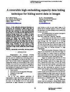
(a)
(b)
Figure 2: (a) Elaine image: (a) original, and (b) marked (PSNR = 50.5 dB)
Hellenic Open University: Technical Report HOU-CS-TR-2006-08-GR
6
E. Varsaki, V. Fotopoulos, A. N. Skodras, ‘A reversible data hiding technique embedding in the image histogram’
Yes
Original image Satisfactory Capacity Histogram calculation
Selection of the peak and zero points
No
Selection of more peak point pairs
Histogram shifting Yes
Other peak point pairs available? No
Embedding
Fail Marked image Figure 3: Data embedding flow chart (black one represents the flow chart with only one pair of zero and peak points, green one represents the supplement of the algorithm for multiple minimum and maximum points).
In case where the payload is bigger than the capacity of one pair of zero and peak points, the algorithm uses two pairs of points and it is well understood that the next points would be local maximum and minimum points. As many pairs as possible can be used to embed the message, until the modification of all image’s pixels. The embedding algorithm with multiple pairs of maximum and minimum points is outlined in the next paragraph.
2. B.
The embedding algorithm using multiple pairs of local minimum
and maximum points. Without loss of generality, the algorithm presented below is for the case of three pairs of maximum and minimum points. It is straightforward to generalize in order to handle the cases where any number of multiple pairs of maximum and minimum points is used. 1.
For an M x N image with pixel grayscale values x ∈ [0,255] , the histogram H(x) is generated.
Hellenic Open University: Technical Report HOU-CS-TR-2006-08-GR
7
E. Varsaki, V. Fotopoulos, A. N. Skodras, ‘A reversible data hiding technique embedding in the image histogram’ 2.
In histogram H(x), three minimum points h(b1), h(b2), h(b3) are found. Without loss of generality, it is assumed that the three minimum points satisfy the condition: 0 < b1 < b2 < b3 < 255.
3.
In the intervals of (0, b1) and (b3, 255) the maximum points h(a1), h(a3) are found respectively and it is assumed a1 ∈ (0, b1 ) , a 3 ∈ (b3 ,255) .
4.
In the intervals (b1, b2) and (b2, b3) the maximum points in each interval are found. It is assumed to be h(a12), h(a21), b1 < a12 < a21 < b2 and h(a23), h(a32), b2 < a23