Page 1. A ROBUST TYPE-III DATA HIDING TECHNIQUE AGAINST CROPPING & RESIZING ... tacks (i.e. cropping, resizing, rotation, uniform/non-uniform scal-.
A ROBUST TYPE-III DATA HIDING TECHNIQUE AGAINST CROPPING & RESIZING ATTACKS Husrev T. Sencar1 , Mahalingam Ramkumar2 , Ali N. Akansu1 1
New Jersey Institute of Technology Electrical and Computer Engineering Department 07102 Newark, New Jersey 2 IDT Corp. / AVWAY.COM Inc. 07102 Newark, New Jersey ABSTRACT We propose an oblivious information hiding method which allows watermark recovery for signals subjected to cropping and resampling consecutively. We employ multiple embedding of a watermark signal using a Type - III data hiding method which has a better robustness vs. rate trade off than the conventional methods under mean square error distortion measure. Cyclic autocorrelation features of the cropped-resampled signal are used to estimate the amount of cropping. We analytically showed that within a small error range, it is possible to restore the croppedresampled signal to the cropped signal. Synchronization of watermark detection in the cropped stego-signal is achieved by designing white noise like watermark signals that are uncorrelated with their shifted replicas. For this purpose we use all-pass filters which are orthogonal to all their cyclic shifts. Freedom to hide data is obtained by modulating the phase of the cyclic all-pass filters. Further, we use Reed-Solomon error correcting codes both for introducing redundancy and achieving synchronization. We also address the issue of data hiding under multiple cropping attacks. 1. INTRODUCTION Among the three conflicting goals of data hiding, robustness and imperceptibility are more important in watermarking applications rather than hiding rate. Watermarking methods will achieve one degree of robustness as their capability of hiding at relatively higher rates is improved against a variety of well known spatial domain attacks (i.e. cropping, resizing, rotation, uniform/non-uniform scaling, DA-AD conversion, quantization.) However, existence of vast variety of attack scenarios make it a challenge to devise widely accepted or “universal” watermarking schemes. Spatial domain attacks can be classified into two main groups namely invertible and non-invertible attacks. Invertible attacks can be reversed by some intelligent and usually computationally intense manipulation. Therefore, hiding rate is not decreased. On the other hand, non-invertible attacks like cropping, AD-DA conversion and compression may lead to insignificant hiding rates if they are not taken into account by the designer. A true watermark embedding methodology should either be invariant to these attacks or include practical means of undoing and reducing the disturbing effects of them. Most of the proposed methods in the literature depend on a particular transform domain for embedding which is immune to some of these attacks. Yet, drastically low hiding rates may still be unavoidable for some others.
In this paper we present an embedding method which allows watermark recovery for signals subjected to cropping and resizing consecutively. These attacks pose a threat of poor watermark detection due to signal transformation and signal loss. We propose practical solutions to aforementioned problems by restoring the resampled signal to its original size and devising ways to synchronize the watermark detection with the embedding. Watermark signals are embedded using a type-III data hiding method, [1, 2], which has a better rate vs. robustness trade off than conventional methods. It is assumed that watermark detector has no access to cover signal (oblivious data hiding.) Resizing is a transformation onto signal and watermark detection performance relies on either a transform invariant embedding or to invert the transformation before detection. Kutter, [3], proposes a scheme which makes use of autocorrelation to determine affine distortions by comparing the extracted and original watermark locations in an image. We use cyclic autocorrelation peak pattern for computing the amount of cropped data (i.e. number of deleted coefficients in a vector and number of pixels of line in an image.) We analytically show that cropping done up to two different signal locations can be calculated within an ignorable error. The information loss due to cropping is countervailed by multiple embedding of the watermark signal. Although, multiple embedding is not an ultimate remedy to cropping, the assumption is that at least some replicas of the watermark signal will be undistorted. Erasures in the stego-signal require reinstatement of synchronization. We achieve synchronization by designing watermark signals in form of all-pass filters which are orthogonal to all their cyclic shifts. The phase of the all-pass filter is modulated by the message to be conveyed. Reed-Solomon error correcting codes are used for both introducing redundancy and achieve synchronization as will be evident in section 4. In the next section, we present a description of the Type-III data hiding method. In section 3, we provide analysis and results for determining the resampling factor (change in aspect ratio for images) in order to restore the stego-signal. Watermark signal design and synchronization issues due to cropping attack are also addressed in the same section. In section 4, we present the results and implementation details for the overall data hiding system. 2. DATA HIDING METHOD A Typical data hiding system may be represented in an additive channel model as
W :
W
S^ Y ^ W
1
= = = :
T1
m ! W; E (S; W ) = S + X; E (S; W ) + Z = S + X + Z; D(Y ); ^ ! m: W ^
D
(E D)
E
D
(E D)
�
��
T1
Te
W
0
T1
(1)
In the above model m is the message to be hidden, S is the cover data, W is the watermark signal, X is the distortion introduced by the hider, and Z is the intrusion of the attacker. is a one-to-one mapping from m to W which transforms message m into a better representation for embedding. Not evident in the model is the distortion constraints imposed on embedding and attacking for keeping the cover signal intact. Ideally, the measure used for quantifying the hider’s and attacker’s distortion is expected to be in compliance with the perceptual properties of the cover signal. The embedder, , and the detector, , may be linear or nonlinear and not necessarily invertible functions. Among available in the various choices of embedder-detector sets ; literature, data hiding methods may be categorized into three main types. Type-I methods are very common and simple to implement. Stego-signal is generated by adding the watermark signal to the cover signal. In the model the distortion X is the watermark signal itself. These methods suffer from dramatically low hiding rates because of the non-optimal design which assumes S as a noise and tries to cancel it. Type-I methods are preferable only when the attack is too severe. Besides, they are ideal only for applications for which the cover data is present at the detector. Type-II methods are characterized by the use of quantizer structures in the embedding and detection. The distortion, X , is a function of S and W . Also, the embedder, , and detector, , are inverses of each other. Disadvantage is that the system performs well only if the attack is low. These can also be employed with oblivious data hiding systems at considerable hiding rates. Type I and II methods have better performances on the two extremes corresponding to severe attack and no attack cases, respectively. An optimal design will be the one that designer has control over the operating characteristics of the method. In [1] Ramkumar proposed a modification to the Type-II methods by removing the invertibility condition on the set ; . In Type-III methods added non-invertibility is designed in a particular way that hiding rate is maximized for a presumed attack level. Type-III data hiding is optimal for oblivious data hiding applications. The embedder being utilized by the data hiding technique is a quantizer characterized by a pair of parameters, period and threshold where < . The form of quantizer used for implementation is a periodic continuous triangular function. Watermark signal to be embedded is limited by the peak values of the periodic function. Embedding is a translation of the input coefficient values by introducing distortions thresholded to 2 such that the mapping of embedded coefficient over the periodic function has a minimum Euclidean distance to the watermark signal. The period and threshold of the quantizer are dictated by the preassigned embedding distortion, above which perceptual features of the cover signal will be considered changed. Among the , pairs that meet the distortion constraint the one that maximizes hiding rate for a presumed distortion level is picked. Detection of the watermark signal is similar to embedding. The stego-signal
E
T1
�
�
�
T2
T2
T2
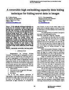
Fig. 1. Representation of cropping and resampling consecutively.
�
is mapped over the periodic function with the same as used for embedding and the fixed threshold , which adds noninvertibility to the ; set. Mean squared error distance is used as the measure of distortions introduced by information hider and attacker.
=�
ED
3. CROPPING AND RESAMPLING Benefits of multiple embedding of the watermark signal is twofold. First, multiple copies of the watermark signal is available for message extraction. Second, autocorrelation techniques can be used to detect the periodicity features of the signal. Figure 1 is a representation of signal cropping and resampling. A signal of length T1 is repeatedly concatenated to generate a periodic signal (first row.) Then, an amount Te starting from an arbitrary point of this signal is cropped out (second row) and remaining signal is resampled by some factor TT21 (third row.) Autocorrelation of the resultant signal can be used to estimate Te with a small error assuming there are un-spoiled periods of signals.
3.1. Autocorrelation for restoring the cropped signal Consider a signal V , obtained by combining n replicas of the signal W , its cropped version VC and its cropped-resampled version VCR are generated as displayed in Figure 1. Let signal W be of length T1 , n be a large integer number, Te be the amount of signal cropped from V , and L be the length of the resultant signal VCR . L Then the resampling factor is �1 nT1 Te . We may also introL duce the factor � nT1 as a measure of deviation from the signal V in terms of size due to resampling. Autocorrelation function of the signal VCR will point out to existence of two periodic components with the same period, T2 T1 �1 . First component is identified by peaks at every T2 shift of the origin in the autocorrelation function. On the other hand, second one generates peaks at a shift of T2 Te �1 from the zero shift and at every T2 shift thereafter. The first component is due to existence of the multiple resampled copies of signal W in VCR and second one appears due to erasures. After every shift of T2 Te �1 following a T2 shift the incomplete signal period coincides with a copy of itself and generates a peak in the autocorrelation function. Also, the latter is much more weaker in signal strength compared to the former. Other than the peak at the zero shift every peak at T2 shifts will be accompanied by another one assuming n is large enough. T 2 T2 Distance d between the peak at kT2 , k n, and k Te �1 is
=
=
=
�
( 1) +
�
= kT2 (k 1)T2 + T2 = Te 1 :
d
Te
1
�
�
;
The error in estimating Te because of scaling by � represented in more explicit terms as
= Te �1 ; = Te nT1L Te ; 1 ; = Te nT�nT 1 Te
(3)
In a typical watermark attack scenario the attacker is not willing to make radical changes in the signal size of V . Reevaluating the Eq. 3 for � d can be approximated as
d � Te + Te (
nT1
Te
)
(4)
The percentage error for using d instead of the actual value of Te Te is nT100 . (e.g. For a given vector of length if coef1 Te ficients are removed and than the cropped vector is resampled back samples, d is computed as : .) The difference between d to and Te can be minimized by increasing nT1 . When Te is greater than T1 an alternative expression of Te for some integer s and an sT1 Teff . amount Teff that satisfies < Teff < T1 is Te The consequence of Te T1 on autocorrelation function is that s number of peak pairs expected to be observed in autocorrelation function will disappear and remaining peaks will indicate an erasure of Teff . So, effective erasure amount, Teff , is the modulus of Te with respect to T1 . Eq. 3 can be modified to
%
512 25
512
26 3
�
0
3.3. Practical concerns The problem is that some correlation peaks may be buried in noise making peak detection unreliable. Using cyclic autocorrelation and designing white noise like W signals are two remedies against it. 3.3.1. Cyclic autocorrelation Cyclic autocorrelation enhances the correlation peaks while suppressing the ground noise due to signal wrapping in autocorrelation function. Assuming multiple croppings of Te1 ; : : : ; Tem Pj=m Tej ; nT Pj=m Tej will signals in the range nT2 2 2 j =1 2� j =1 �
(
= Te �(1 + nT1Te Te ): Te
Tej � for
the distance d between the first and last peaks in a T2 shift can be used as an approximation to the total erasure amount, Te .
1 may also be
�1
8i; l such that i 6= l and i; l � m, : : : , 8j and j � m, and at kT2 if Pmi=1 Tei < T2 . Then,
Tej j =1;j 6=i;l � for
(2)
�
d
Pj=m
kT2 kT2
=
+
(0
℄
Pj=m Tej ℄. The new
nT2
be flipped and added onto range ; 2 j =1 2� location of a peak after signal wrapping always coincides with another peak whose location can be found by subtracting from nT2 P Pj=m Tej , kT Tei j =m Tej 2 � j =1 � . For instance peaks at kT2 j =1 � for i m and kT2 will be translated to n k T2 , n k T2 Pj=m Tej and n k T Pj=m Tej , respectively. Simi2 j =1 � j =1;j 6=i � larly, assuming VCR has been cropped once, by Te samples, peaks T Te and e at kT2 and kT2 � will be translated to n k T2 � n k T2 making it easier for peak detection algorithm. Figure 2 displays the cyclic autocorrelation functions, RVC VC , of a periodic signal. Signal W is assumed to be of size 90 and V is generated using replicas of it. Figure 2-a is cropped once by removing first 30 samples of sixth period and Figure 2-b is cropped twice by removing middle 40 samples of third period and last 20 samples of fifth period (lower). Every shift of size 90, corresponding to size of W , contains two peaks in 2-a and 4 peaks in 2-b. The distance between the peaks in the former is and the distance between the first and fourth in the latter is .
�
(
(
(
)
) (
(
)
)
)
11
60
30
1
d = Teff
=
+
+ Teff ( nT1Te Te ) + sT� 1 ;
RV V(m), Normalized Correlation
0.9
0.8
(5)
0.7
0.6
sT1 Teff . The first term in Eq. 5 is the distance where Te between the peak pairs and second one is the number of periods of W signals missing in the autocorrelation function of VCR .
0.5
0.4
0.3
0.2
0.1
0
(
�
1)
2 2
8
�
30
60
90
120
150
180
210
240
270
300
330
360
390
420
450
480
420
450
m
1 0.9 0.8 0.7 0.6 0.5 0.4 0.3
VV
+
0
(a) R (m), Normalized correlation
3.2. Multiple cropping Let Te1 and Te2 be the amounts of the non-overlapping cropped signals from V and Te1 Te2 < T2 . Autocorrelation function of VCR will have four peaks in every T2 interval that is k T2 , k n, away from zero shift. These peaks will appear at kT2 Te1 +Te2 , kT 2 T�e1 , kT2 T�e2 and kT2 . The last one is due � to resampled copies of W and has highest correlation value. Others are due to cropped-resampled copies of W and have smaller values. The distance, d, between the first and last peak in any T2 Te1 where the error in assuming d instead of interval will be Te2 + � Te is as in Eq. 5. For more numbers of cropping followed by resampling similar analogy is applicable. If Te1 , : : : , Tem are the amounts of the non-overlapping cropped signals there may be upto m ( m peaks only if each cropping is non-overlapping with the others) number of peaks at every T2 shift of the autocorrelation function. Corresponding peak locations in the autocorrelation function will be Pj=m Tej , kT Pj=m Tej for i and i m, at kT2 2 j =1 � j =1;j 6=i �
0.2 0.1 0 0
30
60
90
120
150
180
210
240
270
300
330
360
390
m
(b) Fig. 2. Computing total cropped amounts using cyclic autocorrelation RVC VC . (a) Cropping once, Te . (b) Multiple cropping, Te1 and Te2 .
= 40
= 20
= 20
3.3.2. Watermark Signal Design Watermark signal W in the Eq. 2 is a one-to-one mapping from message m that embedder makes better use with while embedding.
3.4. Synchronization Restored cropped signal must be repartitioned to get signal W back. Since it is not certain which partitions are affected from cropping, extractor needs some markers for re-establishing the synchronization. Most of the partitions will contain signal W or a translated version of it. While some other partitions may have cropped and translated versions of the watermark signal. We use Reed-Solomon error correcting codes for generating watermark signal W and handling synchronization. Given enough redundancy both robustness against signal loss will be achieved and errorless decoding of most of the partitions will be possible at some cyclic shift of the partition. 4. RESULTS We implemented the methodology on graylevel Lena image. Among the various coding strategies we use Hadamard transform matrix and its negated version as the codebook and the orthogonal rows as the codewords that are employed in generating the watermark signal. Message m is assumed to be a sequence of bits that will be conveyed. The message bit sequence is translated into words. Then, the message words are redundancy coded using Reed-Solomon error correcting codes. Encoded message is BPSK modulated and ordered in a way that fulfills the frequency domain symmetry requirements for the phase of the all-pass filter in order to generate the watermark signal W . Watermark sigall-pass filter which gives designer nal is chosen to be 32�32 4 phase samples to modulate by the coded message 2 m. Then, copies of the watermark signal is embedded throughout the whole image. Distortion introduced by the embedder is approximately 40 dB in PSNR. Watermarked image is cropped and in order to compensate the reduction in size it is resampled back to its original size. At the extractor a copy of the watermarked, cropped, and resampled image is divided into partitions of size W . Watermark detection for each partition is followed by the two dimensional cyclic autocorrelation of the detected set of signals. Using correlation peak pattern cropped amount is estimated. Extractor, knowing an estimate of the total cropped amount but not their locations, resamples the image back to its size after cropping. So that, disturbing effect of the resampling can be reversed or at least minimized. This image is then partitioned for watermark extraction. Since extracted watermark signal may have been cropped and translated, an immediate detection of message m is not possible. Reed-Solomon codes are used to detect message m from the extracted watermark signal since they are capable of correcting burst error. Two-dimensional signal is shifted in rows and columns until an errorless decoding is possible. High redundancy coding will help detecting message m even under severe signal loss. Figure 3 displays the results for the described method applied on Lena image, Figure 3-a. Watermarked Lena image is displayed in Figure 3-b where mean squared error per coefficient due to embedding is : . Figure 3-c is the watermarked image cropped in two different locations. Each cropping is 12 lines of pixels in both horizontal and vertical dimensions. Cropped image is resampled
back to its original size in 3-d. Figures 3 e-f are the projections of the cyclic autocorrelation function onto horizontal and vertical dimensions. Distance between the first and last peaks in a shift corresponding to a size of watermark signal is which has an estimation error of . Image in Figure 3-d is resampled to a size shorter lines of pixels in each dimension, partitioned in by blocks and watermark detected. Decoded signals from each block are averaged and watermark detected. Reed-Solomon codes were successful in detecting the 32 bit message m with no errors.
25
50
50
100
150
150
200
200
250
250
300
300
350
350
400
400
450
450
500
500 50
96
100
150
200
250
300
350
400
450
500
50
100
150
200
(a)
250
300
350
400
450
500
300
350
400
450
500
(b)
50
50
100
100
150
150
200
200
250
250
300 300 350 350 400 400 450 450 500 50
100
150
200
250
300
350
400
450
50
100
150
(c)
R(m), Normalized Correlation
= 510 16
32 � 32
32 � 32
100
512 � 512
32
25
1
1
1
0.9
0.9
0.8
0.8
0.7 0.6 0.5 0.4 0.3 0.2 0.1 0 0
200
250
(d)
R(m), Normalized Correlation
One new constraint is that the signal V should have better autocorrelation features based on the choice of signal W . Designing W as an all-pass filter which is orthogonal to all its cyclic shifts, [4], gives one freedom to hide information by modulating the phase of the W as well as the improved autocorrelation properties. An allpass filter W of size T1 has T12 1 for T1 odd ( T12 2 for T1 even) degrees of freedom.
0.7 0.6 0.5 0.4 0.3 0.2 0.1
20
40
60
80 100 120 140 160 180 200 220 240 260
0 0
20
40
60
80
m
100 120 140 160 180 200 220 240 260
m
(e) (f) Fig. 3. (a) Lena image. (b) Watermarked image. (c) Cropped image after watermarking. (d) Resampled image after cropping. (e) Estimation of cropped amounts from the resampled image (e) in horizontal dimension, (f) in vertical dimension.
5. REFERENCES [1] Mahalingam Ramkumar and Ali N. Akansu, “Self-noise suppression schemes for blind image steganography,” in Proc SPIE Multimedia Systems and Applications, 1999, vol. 3845. [2] Husrev T. Sencar, Mahalingam Ramkumar, and Ali N. Akansu, “Efficient codebook structures for practical information hiding systems,” in Proc CISS, Mar. 2001.
[3] Martin Kutter, “Watermarking resistent to translation, rotation, and scaling,” in Proc SPIE Multimedia Systems and Applications, Nov. 1998, vol. 3528, pp. 423–431. [4] Mahalingam Ramkumar and G. V. Anandand Ali N. Akansu, “On the implementation of the 2-band cyclic filter banks,” in Proc IEEE International Symposium Circuits and SystemsISCAS’99, 1999, vol. 3, pp. 520–523.