Wireless capsule endoscopy has been proposed for use in .... clock and reset signal from the RF carrier and transmits .... The Sputnik (the official name of the.
A review of low-power wireless sensor microsystems for biomedical capsule diagnosis K. Arshak Electronic and Computer Engineering Department, University of Limerick, Ireland E. Jafer Electronic and Computer Engineering Department, University of Limerick, Ireland G. Lyons Electronic and Computer Engineering Department, University of Limerick, Ireland D. Morris Physics Department, University of Limerick, Limerick, Ireland O. Korostynska Electronic and Computer Engineering Department, University of Limerick, Ireland
Keywords Microsensors, Biocomputers, Systems engineering
Abstract The development of a sensor microsystems containing all the components of data acquisition system, such as sensors, signalconditioning circuits, analogdigital converter, interface circuits and embedded microcontroller (MCU), has become the focus of attention in many biomedical applications. A review of the microsystems technology is presented in this paper, along with a discussion of the recent trends and challenges associated with its developments. A basic description of each subsystem is also given. This includes the different front end, mixed analog-digital, power management, and radio transmitter-receiver circuits. These sub-system designs are presented and discussed in a comparative study and final remarks are made. The performance of each sub-system is assessed regarding many aspects related to the overall system performance.
Microelectronics International 21/3 [2004] 8–19 q Emerald Group Publishing Limited [ISSN 1356-5362] [DOI: 10.1108/13565360410549675]
[8]
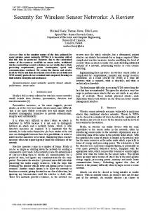
Introduction An adequate knowledge of morphology of the gastrointestinal (GI) tract is necessary for successful planning and performance of motility studies. The GI tract includes the oesophagus, stomach, colon, small intestine, and large intestine as shown in Figure 1. Motility disorder refers to abnormal intestinal contractions, such as spasms and intestinal paralysis, that can result in the inability to eat (which may require patients to receive intravenous nutrition) and severe abdominal pain, nausea, vomiting, maldigestion, weight loss, diarrhoea, constipation and incontinence (Korn and Eddy, 2003). Motility disorders encompass a variety of conditions, including gastroparesis, achalasia, gastroesophageal reflux disease, chronic intestinal pseudoobstruction, constipation and irritable bowel syndrome. Irritable bowel syndrome is the most common of the disorders, resulting in pain and diminished quality of life. Serious disorders produce excruciating pain and make it impossible to eat or digest food (Kingham et al., 1984). Different methods have been used to diagnose the motility disorders and detect the abnormal activities of the GI tract like radiology, manometry, and radio telemetry. Radiology offers qualitative information on the behaviour of the alimentary canal, but at the same time it carries the risk of radiation exposure and therefore, only few and short lasting events can be observed. Radiology is able to detect wall movement caused by contraction of the circular muscle layer, but it is inadequate in the investigation of the longitudinal layer events. Manometry is a second method, which is a technique for recording mechanical activity of the bowel by detecting changes in pressure caused by contractions of the gut wall. The system is an established procedure for the evaluation of GI motility, including diagnostic studies in disease using a perfused tube. A patient can be examined by inserting a manometry tube from the mouth down through the GI tract. The tube is attached from the other side to a pressure transducer, which is connected to a recorder device. Manometry can also be performed through tube-mounted strain gauges. Miniature pressure transducers are available for use as motility probes (Kumar and Gustavsson, 1988). A number of limitations are associated with this technique. First, the manometry in the upper digestive tract and colon is disturbed by solid food components. Secondly, The Emerald Research Register for this journal is available at www.emeraldinsight.com/researchregister
Limerick,
Limerick,
Limerick,
Limerick,
the pressure changes are measured within a sealed cavity, which makes it difficult to get good signals. Wireless capsule endoscopy has been proposed for use in management of patients who have obscure digestive tract bleeding. Patients who have such kind of bleeding present diagnostic and therapeutic challenges because the source of the bleeding is not identified by conventional radiological or endoscopic evaluation. There is only one type of microcapsule which has been introduced recently to improve the health outcome by giving an efficient diagnosation for the GI tract bleeding and other diseases. Radio telemetry is another manometric system with high fidelity. In this system, a pill or capsule consists of a miniaturized microsystem that can be used to study or monitor the GI tract. Recently, different microsystems have been developed and employed successfully for different biomedical applications like microelectromechanical systems (MEMs), capsule endoscopy, and hearing aids. A brief description of different microsystems that can be employed in the telemetry capsules is given below.
Microsystems technology Microsystems technology is defined as an intelligent miniaturized system comprising of sensing, processing and/ or actuating functions, where two or more of the following technologies are combined onto a single or multichip hybrid: electrical magnetic, mechanical, optical, chemical, or biological (McCorquodale et al., 2003). There is a considerable interest in the development of ultraminiature and low-power multisensor microsystems for use in the implanted (Akin et al., 1998), ingestible (Astaras et al., 2002; Johannessen et al., 2002) and remote environmental monitoring (Grimes et al., 2001). Building a complete sensor microsystem involves several challenges as these designs include not only a union of the analog and digital circuit domains, but also the magnetic, mechanical, biological, chemical, or electrical domains. Such systems must exhibit low-cost production, robustness of use and real-time data processing. Many sensor microsystems have been proposed and implemented through the last decade. A typical microinstrumentation system was presented by Kensall (Wise, 1993), which contains a front-end (FE) for three different sensors and actuators, embedded microcontroller, The current issue and full text archive of this journal is available at www.emeraldinsight.com/1356-5362.htm
K. Arshak, E. Jafer, G. Lyons, D. Morris and O. Korostynska A review of low-power wireless sensor microsystems for biomedical capsule diagnosis Microelectronics International 21/3 [2004] 8–19
Figure 1 Simplified diagram showing a micro-capsule inside GI tract
power management and communication units as shown in Figure 2. The FE unit includes the sensor, amplifier and ADC. A smart wireless microsystem has been developed by Mason et al. (1995) and Yazadi et al. (1996) for environmental monitoring and capacitive sensor interface. The system is built around an embedded Motorola 68HC11 MCU having on-chip memory, an 8b ADC, a timer, and serial communications hardware. A block diagram of the system is shown in Figure 3. Sensor data are collected by the MCU, calibrated in-module, stored, and sent out either through an on-board telemetry device or via hardware RS232 I/O port. A custom power management chip performs several functions for minimizing power consumption in the battery-powered system (Mason et al., 1995). The transducers are scanned periodically at a rate determined by the variation in the measured parameters. During each scan, the MCU communicates with the FE
Figure 2 Block diagram of a microinstrumentation system that could be implemented in monolithic or multichip hybrid form
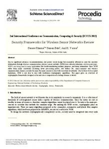
devices over a sensor bus. A similar sensor microsystem fabricated using multi-chip-module (MCM) technology, based on a chip-level infrastructure has been developed by Higino et al. (1997). The first system on chip (SoC) for wireless ultraminiature sensor microsystem suitable for biomedical applications has been developed by Wang et al. (2002) for biomedical applications. Figure 5 shows the function blocks of the present prototypical microsystem. The methodology of SoC is desirable to achieve a low form-factor and low-power consumption. The system comprises of sensors, an application specific integrated circuit (ASIC) with sensor interfaces, analogue and digital systems, a radio transmitter, and a power source. A single ASIC is used for all sensor electronics, including ADC, DAC, microsystem scheduling, coding and transmitter control. The design also employs a simple DSP compression algorithm to achieve low-power serial bit stream transmission, so that power consumption is greatly reduced. A single-chip microinstrument contains programmable analog FE capable of interfacing a variety of sensors has been developed by Kraver et al. (2001). The integrated microcontroller can support both digital filtering and interface compensation of sensor outputs, timing control for sampling multiple sensors, and communications with a host system. Table I shows some of the specifications for the above mentioned wireless sensor microsystems. A description of the two sensor microsystems for biomedical applications will be discussed and a comparative study for each subsystem will be presented. From the given table, it can be concluded that the microsystem presented by Mason et al. (1995) and Yazadi et al. (1996) has the lowest size and power dissipation, which make it a good option for a miniaturized capsule system.
Biomedical microsystems The use of highly integrated microcircuit in bioelectric data acquisition systems promises new insights into the origin of a large variety of health problems by providing lightweight, low-power, low-cost medical measurement devices. A miniature wireless pressure-measuring system is presented by Chatzandroulis et al. (2000) for blood pressure measurements. It uses a sensor based on the capacitive principle and thus, it consumes a very little power. Moreover, its small size makes it suitable for implementation. Recently, a low-power microsystem has been developed for bio-implantable applications (Najafi and Yu, 2003). The system should be capable of sending command data to and retrieve any sensor data transmission and power transfer between the implantable microsystem and an external transmitter/receiver. A conceptual block diagram is shown in Figure 4. In this system, RF interface circuitry receives power and command data from an external transmitter, recovers the clock and reset signal from the RF carrier and transmits sensor data to an external receiver. An amplitude shift keying (ASK) demodulator is designed to decode data from modulated RF carriers. An external class-E power amplifier (PE) is used to derive a coil to deliver power and on-chip electronics, which works well when the induced voltage across the receiver coil is 5.6-15 V. Measured power consumptions for the FE and on-chip transmitter are 476 mW and 1.693 mW, respectively. The power dissipated by the 10-bit ADC is 1.41 mW with 4 MHz clock. A general purpose single-chip CMOS microsystem has been proposed by Senger et al. (2003) based on MEMS technology. The system is comprised of three main subsystems: a digital core, an analog FE, and an on-chip clock reference. The clock reference supplies the digital core and FE with frequency selectable, tuneable reference while requiring less power than an off-chip crystal reference.
[9]
K. Arshak, E. Jafer, G. Lyons, D. Morris and O. Korostynska A review of low-power wireless sensor microsystems for biomedical capsule diagnosis Microelectronics International 21/3 [2004] 8–19
Figure 3 Block diagram of the microinstrumentation system
Table I Summary of characteristics for different developed wireless sensor microsystems Microsystem Wang et al. (2002) Mason et al. (2003) Mason et al. (1995) and Yazadi et al. (1996) Yazdi et al. (1999) Kraver et al. (2001)
Size (mm)
Supply voltage
[ 10 ]
Transmitter frequency
5£5 2.22 £ 2.22 2.2 £ 2.2
Two SR44 Ag2o 1.55 V 3 V battery 6 V external or a battery
13.8 mW 12 mW 400-700 m W
20-40 MHz FSK – 315 MHz
3.2 £ 3.2 3.8 £ 4.1
5 V battery 3 V external or a battery
2.2 mW 10 mW
315 MHz –
Owing to power constraints, the entire microsystem would operate at 900 mV. Another miniaturized low power microsystem has been developed by Claes et al. (2002), which was a part of a dental prosthesis and consists of a multi-channel strain gauge interface. It consists of the mentioned multi-gauge block with an 8-bit DAC, followed by an offset cancelled switched-capacitor amplifier and sample-and-hold and an offset-cancelled 9-bit ADC. The system has been implemented in a 0.7 mm CMOS technology and measures 4.6 mm £ 5.2 mm. The measured mean power consumption of the total system equals to 124 m W per strain gauge channel. Figure 4 Conceptual diagram of the interface for implant microsystems
Power dissipation
Wireless capsule sensor The first radiotelemetry pill used to measure GI motility emerged in the late 1950s. After some initial enthusiasm, its popularity declined until 20 years and later it became an accepted method for monitoring motility (Thompson et al., 1982). In general, radio pills can be made of five compartments: a miniaturized camera, pressure sensing devise, microelectronics, radio transmitter and a battery compartment in the rear. Table II shows a comparison study between radio telemetry and the other mentioned manometric systems (perfused tube and cable mounted sensor). Based on the miniaturization and encapsulation technologies, a number of swallowable wireless telemetric devices appeared. These devices included the ability to measure temperature (CorTempw) (Togawa et al., 1997), pressure (Rigel Ltd) (Kingham et al., 1984; Thompson et al., 1980) and pH (Heidelberg and Bravo capsules) (Barrie et al., 1992; Pandolfino et al., 2003; Ruan et al., 2003) within the GI tract. A summary of these ingestible pills is given and listed in Table III. The first commercial product for GI visualization was developed by Giving Imaging (M2A product) (Fireman and Glukhovsky, 2002; Glukhovsky, 2003), which includes a wireless capsule endoscope, wearable data recorder for wireless reception of data and storage workstation for processing and analysis of the required images. As shown in Figure 5, the capsule has a cylindrical shape of 11 mm in diameter and length of 26 mm.
K. Arshak, E. Jafer, G. Lyons, D. Morris and O. Korostynska A review of low-power wireless sensor microsystems for biomedical capsule diagnosis Microelectronics International 21/3 [2004] 8–19
Table II A comparison of high fidelity manometric systems used to measure GI motility
Fidelity Reliability Ambulant studies Flexibilty of sensor arrangement Patient comfort Durability Availability Current popularity Maximum number of sensors
Radio telemetry
Perfused tube
Cable-mounted sensor
Excellent Good Excellent Excellent Excellent Excellent Good Good 3
Excellent Excellent Poor Acceptable Good Excellent Excellent Excellent 12
Excellent Good Good Poor Good Good Good Acceptable 6
Table III Summary of temperature, pressure and pH telemetry capsules Name
Power source
CorTempw Rigel Research Ltd.
Silver oxide battery Mercury battery
Heidelberg pH capsule Bravo pH system
Saline activated battery –
Capsule dimensions
Sensor range
Other available information
– 8.8 mm£ 6 mm
– 0-300 mmHg
– Sensitivity: 10-40 kHz for 100 mmHg Transmission frequency: 460 kHz – Bravo pH system
20 mm £ 8 mm 6 mm £ 5.5 mm £ 25 mm
The capsule is disposable, ingestible and acquires video images during natural propulsion through the digestive system. The capsule transmits the acquired images via a digital RF communication channel to the recorder unit located outside the body. The data recorder is an external receiving/recording unit that receives the data transmitted by the ingestible capsule. The portable data recorder consists of a sensor array attached to the abdomen. The capsule is made of a specially sealed biocompatible material that is resistant to the digestive fluids throughout the GI tract. SmartPill Diagnostic (2003) system has developed a single use capsule, which is easy to swallow and considered to be as a diagnostic device. The capsule can measure GI (peristaltic) pressure, pH and transit time and transmits its data wirelessly to a mobile receiver/controller. The SmartPill Diagnostic system is composed of the following components: (1) ingestible diagnostic SmartPill capsule, (2) mobile receiver/recorder (for pressure and pH), (3) external antennas (6), and (4) computer with data display proprietary software. The SmartPill measures and transmits data on GI peristaltic pressure, pH and transit time over radio frequencies (RF) received by an array of six antennas that are worn by the patient, through a specially designed vest and wired to a small mobile data receiver recorder that is worn by the patient. When the SmartPill has been excreted, the data are downloaded to a standard PC and processed using proprietary software. The SmartPill’s path through the patient’s GI tract is reconstructed from the RF signals collected from the Figure 5 Schematic diagram of M2A capsule
pH 1-7 PH 1.68-7
device and processed through system software that features a proprietary tracking algorithm. The software also correlates the recorded data values with the device’s precise position, enabling the GI specialist to precisely identify the location of the disease or the abnormal activity. The world’s smallest capsule endoscope has been developed by RF system lab in Japan under the project title “NORIKA” (Norika3 Endoscopic Capsule, 2002). The dimension of a capsule camera is 9 mm in diameter and 23 mm in length. The capsule system consists of micro capsule CCD camera, external controller to wirelessly control and operate the capsule, and coil-embedded vest for power transmission and direction control. The case is made of resin. Inside the capsule, three rotor-coils for posture control are located surrounding the capsule. Around the camera lens, magnetic coils for focus adjustment and four LEDs are placed. In addition, at the centred space area, two tanks with valves are prepared. Finally, a capacitor to store electric power and a microwave video signal transmitter make the NORIKA capsule complete. The system has no battery and instead uses wireless power transmission from outside the body. Figure 6 shows the system capsule, where the AGC is an automatic gain control. Table IV shows a comparison between the M2A, Norika, and SmartPill capsules. There are a number of products, which are classified as electronic pills in the market. An electronic pill produced by a Chinese company (Detai Electronic Pharmacy Co) is said to have a magical effect on diseases of gastroencentric canal and nearby organs, as gastroparesis, local paralysis of intestine, habitual constipation, chronic prostasis, etc. The electronic pill enters gastroencentric canal under the control of a microprocessor and emits encoded pulse that imitating bioelectricity of digestive canal of human body. It directly stimulates smooth muscles, glands and nerves of digestive canal, accommodates movement of gastroencentric, increases secretion of gastroencentric hormone, promotes metabolism of body, etc. Another remarkable product is “The magnetic resonance capsule”, which is developed in Russia and marketed by an Irish company (Turner Clinic of Alternative Medicine, Dublin, Ireland). The Sputnik (the official name of the electronic capsule) emits frequencies lethal to human parasites. It is also used in other treatments such as prostate, gynaecological problems, chronic constipation, gum diseases and general dental toxicity, sexual performance,
[ 11 ]
K. Arshak, E. Jafer, G. Lyons, D. Morris and O. Korostynska A review of low-power wireless sensor microsystems for biomedical capsule diagnosis Microelectronics International 21/3 [2004] 8–19
Figure 6 Norika miniaturized wireless capsule system
Table IV A comparison of different biomedical wireless capsules
Dimension Application Power source Position detection inside GI
Position control function Price Made in
M2A
Norika
SmartPill
11 mm £ 26 mm CMOS endoscopy Battery Yes Analysing strengths of received RF signals No $450 Israel
9 mm £ 23 mm CCD endoscopy Wireless power transition No
22 mm £ 9.6 mm Pressure, pH measure Power No Triangulating radio frequency signals No – USA
diabetes, gastritis, etc. The capsule weighs 5.5 g and its dimensions are 11£22.5 mm. The material is non-toxic and resistant to the environment of the intestinal tract. The strength of the pulse current emitted from the capsule is 10 mA, the amplitude is 4.5 V and the frequency is 50 Hz. The capsule consists of two hemispheres, which serve as electrodes, and it activates itself as soon as it finds itself in a fluid environment, such as the stomach or the intestine, or the fluids of orifices. It then emits the electric pulses of a definite shape, range and frequency. Another microsystem capsule has been developed by Tang et al. (2002). The main features of the system include an integrated sensor array, analog signal conditioning, a digital signal processor, a wireless transmitter and a power source as shown in Figure 7. Two smart power management strategies have been implemented by the system. The primary strategy is to disable “Idle” function blocks during different task phases. The second strategy uses a simple DSP data compression algorithm to achieve low-power serial bitstream transmission. The wireless communication uses FSK modulation method, where the transmitter has a cover range of 1 m and the received signal has signal to noise ratio (SNR) of 78 dB at 20 MHz. The power supply comprises of two standard 26 mAh, 1.5 V silver oxide cells. The entire microsystem fits into a single 16 mm £ 55 mm capsule made of polyether-terketone. The National Aeronautic and Space Agency (NASA) also has developed an “electronic pill” for monitoring vital signs of unborn children. It can be classified as “fetal telemetry” rather than “electronic pill” because it is not intended for treatment. Another capsule type endoscope is under development by the Intelligent Microsystem Center (IMC) in South of Korea (Intelligent Microsensor System, 2001). The capsule consists of many components for actuation, sensing, data acquisition/processing, communication and power source. The capsule is 10 mm in diameter, less than 30 mm in length and designed to move in five different modes: forwards, backwards, pausing, fixing and rotating.
[ 12 ]
Yes $120 Japan
Sensor interface circuits (capacitive and resistive) In this section, different capacitive and resistive readout circuits that can be integrated in a capsule microsensor are described and studied comparatively. These circuits are selected carefully to meet the requirements, such as low power consumption, high precision, auto-calibration, and long-term stability. The probable used sensor interface can be divided mainly into capacitive or resistive as illustrated below.
Capacitive readout circuits A standardized interface for capacitive transducer was designed to interface between the FE transducers and the bus as shown in Figure 8 (Yazdi et al., 1999). In general, a switched-capacitor FE is a good selection for the miniaturized capacitive readout circuits since the gain of this circuit is less sensitive to variations in input parasitic capacitance. A basic switched-capacitor relaxation oscillator used as capacitance transducer is shown in Figure 9 (Cichocki and Unbehauen, 1990). In this circuit, Cx denotes an unknown capacitance (capacitive sensor), Cr is the known reference capacitance and Cf is a non-critical value integration capacitance. The circuit consists of a standard switched-capacitor integrator, a voltage comparator (Schmitt trigger), and a switch control logic. The MOS switches are controlled by a two-phase clock, F1 and F2 and switch control logic with logic signals FA, FB, FC, and FD. Assuming that the control logic signals are described by the following equation: FA ¼ F2 ;
FB ¼ F1 ;
FC ¼ K� 0 F1 ;
FD ¼ K� 0 F2 ð1Þ
The circuit operates as follows. Suppose the voltage comparator is in the high state ðK 0 ¼ 1Þ; i.e. its input voltage VI is negative and its output voltage V O ¼ V B ¼ 2V SS . 0: Then during each clock phase F1, the charge will be: Dqx ¼ C x V B
ð2Þ
K. Arshak, E. Jafer, G. Lyons, D. Morris and O. Korostynska A review of low-power wireless sensor microsystems for biomedical capsule diagnosis Microelectronics International 21/3 [2004] 8–19
Figure 7 Integrated multisensor microsystem for the prototype
Figure 8 Diagram of the capacitive sensor interface chip showing the major circuit blocks. CI is the charge integrator and VGA is the voltage gain amplifier
Figure 9 Capacitive interface based on SC relaxation oscillator
injected into the integrating capacitor Cf and the voltage VI is increased by the value: DV þ I ¼
Cx VB Cf
ð3Þ
until VI becomes slightly positive. Then the comparator changes to the “low state” ðK 0 ¼ 0Þ; i.e. the output voltage becomes V O ¼ 2V B ¼ V SS , 0; the capacitor C1 will then inject a charge (q1): Dq1 ¼ 2C 1 V B
ð4Þ
into the capacitor Cf and hence, VI will jump to the value equal to: Vþ I ¼
C1 VB # VB Cf
with C 1 # C f =2
ð5Þ
At present, the voltage VI will decrease in each clock phase F1 by the value:
[ 13 ]
K. Arshak, E. Jafer, G. Lyons, D. Morris and O. Korostynska A review of low-power wireless sensor microsystems for biomedical capsule diagnosis Microelectronics International 21/3 [2004] 8–19
DV 2 I ¼
Cr 2 Cx VB Cf
with
Cr # Cx
ð6Þ
until VI becomes less than zero, the comparator changes to its high state and the capacitor C1 makes VI more negative by the value: C1 V B: ð7Þ V2 I ¼ Cf Next, the whole operation repeats. The number of clock pulses needed to change the output voltage VO from the value 2C1VB/Cf to zero can be estimated as: Vþ 2C 1 N1 ¼ I 2 ¼ ð8Þ DV I Cr 2 Cx The number of clock pulses required N2 to change the output voltage VO from 22C1VB/Cf to zero is: V2 2C 1 : N2 ¼ I þ ¼ Cx DV I
ð9Þ
Hence, the oscillation frequency is expressed as: f ¼
1 ðC r 2 C x ÞC x h fc T1 þ T2 2C 1 C r
Continuous calibration In order to have a stable sensor interface, the system should be continuously auto-calibrated for additive and multiplicative errors of the electronics. To implement the autocalibration, a reference capacitor Cref and the offset are measured in exactly the same way as the sensor capacitor Cx. This results in three different periods Tref, Toff, Tx, which are given by: T ref ¼ T 0 þ KCref T off ¼ T 0
Eliminating parasitic effects The effect of parasitic capacitors becomes greater when considering a miniaturized capsule system. A two-port measurement technique is developed for the purpose of parasitic reduction as shown in Figure 10. Here, the sensor capacitor Cx is cursed with parasitic capacitors Cp1 and Cp2, modelling the capacitances of the connecting cables. The only way to eliminate the effects of both parasitics is to force a voltage Vtp on the transmitting electrode and to
ð11Þ
T x ¼ T 0 þ KCx where T0 and K represent the offset and gain, respectively. These periods are measured by the microcontroller, yielding digital numbers Nref, Noff, and Nx. The final measurement result M that represents the output relative sensing value is calculated by the microcontroller:
ð10Þ
where fc is the clock frequency. Unfortunately, the above mentioned circuit is sensitive to the offset voltage of the op-amp and to the clock feedthrough of the clock signals through the gate-source and gate drain parasitic capacitors of the MOS. For this reason, the circuit is less precise when measuring small changes in pressure through the GI tract and not suitable when long-term sensing is required because of the autocalibration lack. The above basic circuit has been improved in the work of Cao and Temes (1994) using two different proposed circuits. Hold capacitors are used in the first circuit to reduce the effective value of the op-amp offset voltage and adjust the gain at the same time. The second circuit based on a higher model and has been developed to handle their parasitics effects, which reduce the accuracy of the readout. In the work of Goes and Meijer (1996), a novel low-cost capacitive interface has been implemented using a DC reference voltage that is preferred because a low noise reference can be more easily generated on the chip as compared to a low-noise AC source. The techniques used by the interface to eliminate the parasitic effects and also provide an efficient autocalibration for the interface are explained in the following sections.
Figure 10 Two-port measurement of Cx, Cp1 and Cp2 models the capacitances of the connecting cables
sense the current Itp. The current Itp depends only on Vtp and Cx.
M¼
N x 2 N off Cx ¼ N ref 2 N off Cref
ð12Þ
This ratio does not depend on T0 and K and since this calibration is done continuously, also slow variations in T0 and K do not affect the value of M. One full measurement cycle consists of three time intervals, which we refer to as measurement phases. Combining the three measurement concepts will lead the sensor system to be as shown in Figure 11(a). In order to minimize the number of terminals on the interface, the selection of the three measurement phases is made by the interface itself and only one terminal can be used for the communication with the microcontroller. Figure 11(b) shows the output signal of the sensor interface over a full measurement cycle. A great advantage of the signal type shown in Figure 12 is the low-pass filtering of this signal, which does not cause the value M to change. A serious problem that arises while using this system, is caused by low-frequency (LF) interference. These interfering signals can be either filtered or removed by adjusting the oscillator frequency to be immune to LF signals. The above capacitive interface system has been improved by Li and Meijer (2002), based on the use of on the first-model switched capacitor (SC) relaxation oscillator. In the new interface, a continuous autocalibration of the offset and gain of the complete interface are performed. The first-order SC oscillator uses a third-order filter to suppress LF interference. This also results in a very low sensitivity to 1/f noise, enabling the use of low-cost CMOS processes for the implementation of accurate circuits. Another factor, which has been taken into consideration in the above system, is the effect of the parasitic shunt conductance, which causes inaccurate capacitance measurements. The circuit specifications are suitable for a low-power integrated biomedical unit such as pill telemetry. In this case, the microcontroller has less of a role, as there is no need for circuit calibration and the use of the op-amps. The capacitance/frequency (CF) converter has been employed for pressure-measuring subsystem in implantable applications (Chatzandroulis et al., 2000; DeHennis and Wise, 2002). Such a converter is implemented with Schmitt-input ring oscillator and complimentary pass gates to provide switching between the sensor Csens, the reference Cref, and the null state. The switchable C-F conversion and frequency-division circuitry is shown in Figure 12. Table V shows the basic functions for the different capacitive systems.
Resistive readout circuits Different basic circuits have been developed and implemented for resistive sensors in recent years. From a
[ 14 ]
K. Arshak, E. Jafer, G. Lyons, D. Morris and O. Korostynska A review of low-power wireless sensor microsystems for biomedical capsule diagnosis Microelectronics International 21/3 [2004] 8–19
Figure 11
Figure 12 Schematic diagram of the switchable Schmitt trigger oscillator used for capacitance to frequency conversion
Table V A comparison of interface circuitry suitable for capacitive sensors System
Circuit
Cichocki et al. Van der Goes et al.
Based on relaxation oscillator
Capable of eliminating parasitic effects No Parasitic capacitors
Li et al. Chatzandroulis et al.
Based on Schmitt trigger oscillator
Parasitic capacitors and shunt conductance No
Calibration style
Efficiency
Non Auto-calibrated for additive and multiplicative errors Auto-calibrated for additive and multiplicative errors Compensation by reading the reference capacitor
Moderate High Very high High
Figure 13 shows the Wheatstone bridge configuration. The output voltage of the bridge circuit is given by the following equation (Arshak et al., 2003): � � Rx R3 2 ð13Þ V out ¼ V in Rx þ R1 R2 þ R3
In order to utilize the characteristics of a bridge topology, a number of limitations must be considered: . half of the signal from element impedance change is attenuated by the adjacent bridge arms; . the output signal is usually a nonlinear function of impedance change per individual bridge arm; . multiple sensing impedances observed simultaneously will provide only a single output signal; and . only one measurement output can be obtained from the variation in each individual sensing impedance.
The sensitivity of the circuit is given by:
Anderson loop topology
biomedical point of view, our focus is concentrated on three of them.
The Wheatstone bridge
S¼
›V out V IN R1 ¼ ›Rx ðRx þ R1 Þ2
ð14Þ
This has been developed as a new measurement circuit, which represents a challenge to the venerable Wheatstone bridge in a number of application areas (Anderson, 1998).
[ 15 ]
K. Arshak, E. Jafer, G. Lyons, D. Morris and O. Korostynska A review of low-power wireless sensor microsystems for biomedical capsule diagnosis Microelectronics International 21/3 [2004] 8–19
0-400 V, with a resolution of 7 mV and an accuracy of 11 mV. The three-signal auto-calibration technique described earlier has applied in a circuit to reduce the common-mode effect as explained for the capacitive interface. In order to implement this technique, the sensor Ex, reference Eref, and offset Eoff signals are to be measured with output signal Mi
Figure 13 The Wheatstone bridge arrangement
M i ¼ KEi þ M off
ð16Þ
After the implementation of the three-signal auto-calibration technique, the final measuring result in the ratio, M¼
In this topology, a practical dual-differential subtractor with sufficiently high input impedance and rejection of unwanted signals has been introduced as shown in Figure 14. Here voltage drops along current-carrying lead wires, Zw1 and Zw2 are simply not included in the signals being processed. No significant voltage drop occurs along the sensing lead-wires, Zw3 and Zw4. When the reference impedance Zref is chosen to be equal to the initial impedance Zg of sensing element, the subtractor inputs are processed with unity gain, the output is: vout ¼ iDZ
ð15Þ
The results indicate that the loop has an inherently linear response to changes in a sensor element and no impedance terms are present to attenuate the output. Some of the other circuit benefits are: . larger and inherently linear outputs that are individually available from each element in a sensor; . power dissipation of the sensor is lowered-beneficial in portable and temperature sensitive applications, which is required for the pill microsensor systems; . fewer, smaller and inexpensive lead wires are required in tight installations; and . smarter biomedical sensors can be designed to deliver multiaxis and multiparameter outputs from simpler sensing features.
Relaxation oscillator resistive interface An accurate and smart resistive sensor interface based on the use of a relaxation oscillator has been proposed by Li and Meijer (2002). The system is able to measure a resistance of Figure 14 The Anderson loop measurement circuit topology
[ 16 ]
M x 2 M off Ex ¼ M ref 2 M off Eref
ð17Þ
Figure 15 shows a simplified block diagram of the proposed interface system. The interface mainly consists of a charge to period converter that employs the relaxation oscillator, a multiplexer and a logic control circuit. This interface is very suitable for implementation in the low-cost CMOS technology. Table VI summarizes the basic characteristics of the three resistive motioned circuits. For a resistive sensor integrated in a capsule, all the above-described circuits can be implemented but with different level of performance. A Wheatstone bridge is a simple and sensitive circuit to the temperature changes. However, it gives mostly nonlinear attenuated output values, so it may need an extra circuitry for continuous calibration. On the other hand, the Anderson loop is a stable circuit, which is required for long-term operation and it provides a linear output. Such a circuit is suitable to be employed in a diagnostic system for sensing and recording different parameters inside the GI, which may take a few hours or few days. The smart interface circuit can be modified to be a general capacitive-resistive interface, which is required for a miniaturized system design. The interface also has low power dissipation and provides a continuous calibration to eliminate the scale and offset errors of the sensing values. It should be mentioned that the system is developed to measure a low sensor resistance, so it has a limited sensing range.
Radio frequency circuitry Any standard receiver is suitable for wireless sensor, but some are sensitive, selective or display lower noise than others. They are generally rugged, well engineered, and reliable and use readily available batteries. Some cover the AM band (530-1600 kHz) and others also cover the FM band (88-108 MHz) (Mackay, 1993). Radio-pills can use either AM or FM radio wavebands for transmission. Most RF transceivers used for biomedical applications are implemented as multi-chip modules based on multiple technologies. Baseband and digital components are predominantly silicon CMOS as shown in Figure 16. The low-noise amplifier (LNA), mixer, and power amplifier (PA) are typically GaAs, Bipolar Si is used for phase-locked loop (PLL) and voltage-controlled oscillator (VCO) (Melly et al., 2001). The FE, the resonant tank, and filters are comprised of discrete passive components. The implementation has shortcomings: greater size, weight, and cost. In addition, parasitics arising from module interconnections also deteriorate the performance. However, no single technology can support a commercially single-chip RF transceiver, making this hybrid approach the optimum one. Technology comparisons for RF microsystems explore the advantages and disadvantages of each of the competing technologies – Si CMOS, Si BJT, SiGe HBT, and GaAs MESFET, HEMT and HBT for specific application. Table VII compares some practical issues for RF microsystem technologies (McShane and Shenai, 2000). Although HEMTs offer excellent RF performance, concerns of manufacturability, reliability and cost render them
K. Arshak, E. Jafer, G. Lyons, D. Morris and O. Korostynska A review of low-power wireless sensor microsystems for biomedical capsule diagnosis Microelectronics International 21/3 [2004] 8–19
Figure 15 Block diagram of the smart resistive sensor interface employing relaxation oscillator
Table VI A comparison of the three basic types of interface circuit suitable for resistive sensors Interface
Circuit-based
Auto-calibration
Output linearity
Number of Sensors
Cost
Bridge Anderson Smart
Passive subtraction Active subtraction Relaxation oscillator
No No Yes
Non linear output per bridge arm Linear output from each element Linearity improved with multiple signal calibration
1-4 Not limited Not limited
Expensive Low Low
Figure 16 A simplified overview of the conventional transceiver. The frequency synthesizer (LO block) is shared between the receiver and the transmitter
Table VII Practical issues for RF microsystem technologies Technology
Integration
Passives
Manufacture
Reliability
MESFET P-HEMT InP-HEMT GaAs HBT Si BJT SiGe HBT Si CMOS SOICMOS
Fair Fair Fair Fair Poor Poor Fair Good
Good Good Good Good Poor Poor Poor Excellent
Good (small wafers) Fair expensive Fair expensive Good (small wafers) Very good Fair (expensive) Excellent Good
Good Good Fair Fair Very good Unknown Excellent Very good
unsuitable for commercial applications. GaAs offer excellent RF performance and a high-resistivity substrate for passive component integration. Wafer size, cost, and process reliability prevent GaAs from spreading to logic or
mixed-signal circuitry; it is limited to selected RF applications. Si/SiGe BJTs are also limited to RF applications, and are not suitable for integration of digital and analog circuits. Although both Si BJTs and SiGe HBTs
[ 17 ]
K. Arshak, E. Jafer, G. Lyons, D. Morris and O. Korostynska A review of low-power wireless sensor microsystems for biomedical capsule diagnosis Microelectronics International 21/3 [2004] 8–19
are compatible with BiCMOS processes, the bipolar portion of such processes is not accurately characterized and is usually unoptimized. State-of-the art performance comparable to Si BJT and GaAs MESFET is reported using Si CMOS technology. Rapid advances have been made in the integration of passive components on Si. These advances coupled with the overwhelming dominance of CMOS in the digital area present Si CMOS as the best candidate for single-chip solution to RF microsystems. The RF performance of Si CMOS will perhaps never match that of GaAs or SiGe, but its integration potential, bolstered by the cost advantage of an established technology, will provide the necessary impetus. Silicon on insulator (SOI) devises thus appear to be an ideal technology for mixed signal circuit implementation. Demonstration of SOI CMOS RF devices and passive components, with performance surpassing GaAs MESFETs, has confirmed the potential of SOI in RF applications. SOI technology is maturing to the stage where it can support ultra-low-power RF microsystems.
data. Each bit is used for channel recognition of control signal from outside the body. Since CMOS image sensor module consumes most of the power compared to the other components in the telemetry module, controlling the ON/OFF of the CMOS image is very important. Moreover, since lighting LEDs also use a significant amount of power; the individual ON/OFF control of each LED is equally necessary. As such, the control signal is divided into four channels in this study. Each part of the above proposed telemetry system could be designed and implemented individually, considering the effects of other parts. Mainly the system design can be divided into five parts. They are: (1) design the RF communication link between the module or capsule and an external device; (2) design the image or any other sensors; (3) design the microsystem to organize the flow of data and signals inside the capsule; (4) miniaturizing and packaging the prototype developed system; and (5) design efficient software to receive the data and display it on the PC screen.
Case study: design a miniaturized telemetry module The proposed miniaturized wireless telemetry capsule consists of a CMOS image sensor, lighting LED transmitter and receiver circuits, two antennas, and battery as shown in Figure 17. A bi-directional and multi-channel wireless telemetry capsule, 11 mm in diameter, was designed and implemented, it can transmit video images from inside the human body and receive control signals from external control units. The capsule also includes two 10 mm diameter loop antennas, one for transmitting the video signal and the other for receiving the external control signal. Since 315 MHz is the commercial cable channel frequency for a cable TV broadcasting system, users can watch the images of the intestine on a TV using CH 39, which is a hyperband cable channel. For building the RF receiver, a commercialised ASK/OOK modulator was used. This receiver used is a single chip with a remote wireless communications, which includes an internal local oscillator fixed at a single frequency, is based on an external reference crystal or clock. Plus the decoder IC receives the serial stream and interprets the serial information as four binary
Figure 17 Conceptual diagram of bi-directional wireless endoscopy system
[ 18 ]
Discussion A review of microsystems, interface circuits, and RF technologies, which has been employed as a part of a wireless capsule system has been carried out. Different capsule systems, which have been either commercialized or developed in a prototype stage, have been described and studied comparatively. The relevant sensor interface circuits have been presented and discussed. Advantages and disadvantages of each system and the circuits have been explored fully. A capacitive sensor interface based on relaxation oscillator and continuous autocalibration was found to be a suitable option for a low power-cost design. Of the resistive interface circuits reviewed, it has been concluded that Anderson loop gives a good and stable performance. A simple telemetry module system has been proposed at the end, which reflects a possible future system design.
References Akin, T., Najafi, K. and Bradley, R. (1998), IEEE Journal of SolidState Circuits, pp. 109-18. Anderson, K.F. (1998), IEEE Instrumentation and Measurement Magazine, Vol. 1, pp. 5-15. Arshak, K., Lyons, G., Cavanagh, L. and Seamus, C. (2003), Sensor Review, pp. 230-41. Astaras, A., Ahmadian, M., Aydin, N., Cui, L., Johannessen, E., Tang, T., Wang, L., Aslan, T., Beaumont, S., Flynn, B., Murray, A., Reid, S., Yam, P., Cooper, J. and Cumming, D. (2002), Proc. IEEE ICBME conf., Singapore. Barrie, S.A. and Pizzorno et al. (1992), A Textbook of Natural Medicine: Heidelberg pH Capsule Gastric Analysis. Cao, Y. and Temes, G. (1994), IEEE Transactions on Circuits and Systems, pp. 637-9. Chatzandroulis, S., Tsoukalas, D. and Neukomm, P. (2000), IEEE Microelectromechanical Systems, Vol. 9, pp. 18-23. Cichocki, A. and Unbehauen, R. (1990), IEEE Transactions on Instrumentation and Measurement, pp. 797-9. Claes, W., Puers, R., Sansen, W., De Cooman, M., Duyck, J. and Naert, I. (2002), Sensors and Actuators, pp. 548-56. DeHennis, A. and Wise, K.D. (2002), Digest of the Solid-State Sensor and Actuator Workshop, Hillton Head. Fireman, Z. and Glukhovsky, A. (2002), Wireless Capsule Endoscopy, Vol. 4, pp. 717-9. Glukhovsky, A. (2003), Sensor Review, Vol. 23, pp. 128-33. Goes, F.M.L. and Meijer, C.M. (1996), IEEE Transactions on Instrumentation and Measurement, pp. 536-40. Grimes, C., Jain, M., Singh, R.S., Cai, A., Takahata, K. and Gianchandani, Y. (2001), Proc. 14th IEEE Conf. Microelectromechanical Systems, pp. 278-81. Higino, J., Cretu, E., Bartek, M. and Wolffenbuttel, R.F. (1997), Symposium on Industrial Electronics, Guimaraes, Portugal, pp. 846-50.
K. Arshak, E. Jafer, G. Lyons, D. Morris and O. Korostynska A review of low-power wireless sensor microsystems for biomedical capsule diagnosis Microelectronics International 21/3 [2004] 8–19
This work was supported by Enterprise Ireland Commercialization Fund 2003, under technology development phase, as part of the MIAPS project, reference no. CFTD/03/ 425. Funding was also received from the Irish Research Council for Science, Engineering and Technology: funded by the National Development Plan.
Intelligent Microsensor System (IMS News Letter) (2001), 1st ed., No.1. Johannessen, E., Tang, T., Wang, L., Cui, L., Ahmadian, M., Aydin, N., Astaras, A., Murray, A., Flynn, B., Aslan, T., Beaumont, S., Cumming, D. and Cooper, J. (2002), Proc. of the mTAS Symposium, Japan, pp. 181-3. Kingham, J.G.C. and Bown, R. et al. (1984), “Jejunal motility in patients with functional abdominal pain”, Gut, Vol. 25, pp. 375-80. Korn, A.M. and Eddy, D.M. (2003), Wireless Capsule Endoscopy, Vol. 17, pp. 1-14. Kraver, K.L., Guthaus, M.R., Strong, T.D., Bird, P., Cha, G., Hold, W. and Brown, R. (2001), Sensors and Actuators, Vol. 91, pp. 266-77. Kumar, D. and Gustavsson, S. (1988), An Illustrated Guide To Gastrointestinal Motility, Wiley, New York, NY. Li, X. and Meijer, G.C.M. (2002), IEEE Transactions on Instrumentation and Measurement, Vol. 51, pp. 935-9. Mackay, R.S. (1993), Bio-Medical Telemetry: Sensing and Transmitting Biological, IEEE Press information, New York, NY. Mason, A., Yazadi, N., Najafi, K. and Wise, D. (1995), Proc. Eurosensors Conf., Stockholm, Sweden. Mason, A., Yazdi, N., Zhang, J. and Sainudeen, Z. (2003), IEEE Symposium on Circuits and Systems (ISCAS), Bangkok, Vol. 3, pp. 926-9. McCorquodale, M., Gebara, F., Kraver, K., Marsman, E., Senger, R. and Brown, R. (2003), Proc. IEEE Design, Automation and Test in Europe DATE, pp. 292-6. McShane, E. and Shenai, K. (2000), Technologies and Design of Low-Power RF Microsystems, Vol. 1, pp. 107-15. Melly, T., Porret, A.S., Enz, C. and Vittoz, E.A. (2001), IEEE Solid - State Circuits, Vol. 36, pp. 467-72. Najafi, K. and Yu, H. (2003), Solid-States Circuits Conference ISSCC, Digest of Technical Papers, pp. 194-487. Norika3 Endoscopic Capsule (2002), Data sheet.
Pandolfino, J.E. and Richter, J.E. et al. (2003), “Ambulatory esophageal pH monitoring using a wireless system”, The American Journal of Gastroenterology, Vol. 98 No. 4, pp. 740-9. Ruan, C. and Ong, K.G. et al. (2003), “A wireless pH sensor based on the use of salt-independent micro-scale polymer spheres”, Sensors and Actuators B, Vol. 96, pp. 61-9. Senger, R., Marsman, E., McCorquodala, M., Gebara, F., Kraver, K., Guthaus, M. and Brown, R. (2003), Proc. Design Automation Conf., pp. 520-5. SmartPill Diagnostics (2003), Data sheet. Tang, T., Johannessen, E., Wang, L., Astaras, A., Ahmadian, M., Murray, A., Cooper, J., Beaumont, S., Flynn, B. and Cumming, D. (2002), IEEE Sensors Journal, pp. 628-35. Thompson, D.G., Valori, R.M. and Wingate (1982), 8th International Symposium on GI Motility, New York, NY, pp. 255-8. Thompson, D.G. and Wingate, D.L. et al. (1980), “Normal patterns of human upper small bowel motor activity recorded by prolonged radiotelemetry”, Gut, Vol. 21, pp. 500-6. Togawa, T. and Tamura, T. et al. (1997), Biomedical Transducers and Instruments, CRC Press LLC, West Palm Beach, FL. Wang, L., Tang, T., Johannessen, E., Astaras, A., Murray, A., Cooper, J., Beaumont, S. and Cumming, D. (2002), IEEE Instrumentation and Measurement Technology Conference, Anchorage, AK, USA, pp. 717-1720. Wise, D. (1993), Solid-states Circuits Conference ISSCC, Digest of Technical Papers, pp. 126-7. Yazadi, N., Mason, A., Najafi, K. and Wise, D. (1996), International Symposium on Circuits and Systems, Atlanta, GA, pp. 336-9. Yazdi, N., Mason, A., Najafi, K. and Wise, K.D. (1999), Sensors and Actuators, Vol. 84, pp. 351-61.
Further reading Li, X. and Meijer, C.M. (2001), IEEE Transactions on Instrumentation and Measurement, pp. 1648-1651s.
[ 19 ]