Articles
A Summary Review of Wireless Sensors and Sensor Networks for Structural Health Monitoring Jerome P. Lynch and Kenneth J. Loh ABSTRACT—In recent years, there has been an increasing interest in the adoption of emerging sensing technologies for instrumentation within a variety of structural systems. Wireless sensors and sensor networks are emerging as sensing paradigms that the structural engineering field has begun to consider as substitutes for traditional tethered monitoring systems. A benefit of wireless structural monitoring systems is that they are inexpensive to install because extensive wiring is no longer required between sensors and the data acquisition system. Researchers are discovering that wireless sensors are an exciting technology that should not be viewed as simply a substitute for traditional tethered monitoring systems. Rather, wireless sensors can play greater roles in the processing of structural response data; this feature can be utilized to screen data for signs of structural damage. Also, wireless sensors have limitations that require novel system architectures and modes of operation. This paper is intended to serve as a summary review of the collective experience the structural engineering community has gained from the use of wireless sensors and sensor networks for monitoring structural performance and health. KEYWORDS: wireless sensors, structural monitoring, damage detection, smart structures, decentralized computing
1. Introduction Structures, including bridges, buildings, dams, pipelines, aircraft, ships, among others, are complex engineered systems that ensure society’s economic and industrial prosperity. To design structures that are safe for public use, standardized building codes and design methodologies have been created. Unfortunately, structures are often subjected to harsh loading scenarios and severe environmental conditions not anticipated during design that will result in long-term structural deterioration. For example, recent seismic events, including the Loma Prieta (1989), Northridge (1994), Kobe (1995), and Chi-Chi (1999) earthquakes, reveal civil structure vulnerability to damage and failure during natural catastrophes. To design safer and more durable structures, the engineering
Professor J. P. Lynch (
[email protected]) and K. J. Loh, Department of Civil and Environmental Engineering, The University of Michigan, 2350 Hayward Street, Ann Arbor, MI 48109-2125, USA. The Shock and Vibration Digest, Vol. 38, No. 2, March 2006 91–128 ©2006 SAGE Publications DOI: 10.1177/0583102406061499 Figures 1, 3–5 appear in color online: http://svd.sagepub.com
community is aggressively pursuing novel sensing technologies and analytical methods that can be used to rapidly identify the onset of structural damage in an instrumented structural system (Liu and Tomizuka, 2003a, 2003b). Called structural health monitoring (SHM), this new paradigm offers an automated method for tracking the health of a structure by combining damage detection algorithms with structural monitoring systems. Structural monitoring systems are widely adopted to monitor the behavior of structures during forced vibration testing or natural excitation (e.g. earthquakes, winds, live loading). Structural monitoring systems can be found in a number of common structures including aircrafts, ships, and civil structures. For example, some building design codes mandate that structures located in regions of high seismic activity have structural monitoring systems installed (International Conference of Building Officials, 2002). The monitoring system is primarily responsible for collecting the measurement output from sensors installed in the structure and storing the measurement data within a central data repository. To guarantee that measurement data are reliably collected, structural monitoring systems employ coaxial wires for communication between sensors and the repository. While coaxial wires provide a very reliable communication link, their installation in structures can be expensive and labor-intensive. For example, structural monitoring systems installed in tall buildings have been reported in the literature to cost in excess of $5000 (USD) per sensing channel (Celebi, 2002). As structural monitoring systems grow in size (as defined by the total number of sensors), the cost of the monitoring system can grow faster than at a linear rate. For example, the cost of installing over 350 sensing channels upon the Tsing Ma suspension bridge in Hong Kong is estimated to have exceeded $8 million (Farrar, 2001). The high cost of installing and maintaining wires is not restricted only to civil structures. Others have reported similar issues with respect to the costs associated with monitoring systems installed within aircrafts, ships, and other large structural systems (MacGillivray and Goddard, 1997). Damage detection methods provide engineers with automated tools that can be used to screen response data for signs of structural distress. Over the past decade, a large number of damage detection methods have been proposed, as reported by Doebling et al. (1998) and Sohn et al. (2004). Damage detection methods can generally be classified as one of two types: local-based or global-based damage detection methods. Local-based damage detection methods attempt
92
The Shock and Vibration Digest / March 2006
to identify damage based on screening structures at their component or subcomponent length-scales. Many non-destructive evaluation (NDE) technologies, including ultrasonic inspection, can be classified as supporting local-based damage detection. While local NDE is suitably scaled to the structural damage phenomena (e.g. cracks, yielding), local-based inspection technologies generally require a trained professional to operate in the field, thereby raising their costs. Furthermore, the operator must have knowledge of potential damage regions to prioritize inspection of the complete structure. For example, post-Northridge structural inspections discovered severe fatigue cracking of steel moment frame connections. As a result of this discovery, all steel moment frame connections in the Los Angeles region have been inspected using ultrasonic NDE; the cost of inspection is reported as $200 to $1000 per welded connection (Hamburger, 2000). Global-based damage detection refers to numerical methods that consider the global vibration characteristics (e.g. mode shapes, natural frequencies) of a structure to identify damage. Global-based damage detection was initially proposed as a result of the availability of structural monitoring systems that could be installed in a structure to collect response time histories. However, with tethered structural monitoring systems expensive to install, the nodal densities of most systems have been low (often, only 10–20 sensors are installed in a single structure). Such small numbers of sensors are poorly scaled to the localized behavior of damage, often rendering globalbased damage detection difficult to implement. Particularly for structures exposed to widely varying environmental and operational loadings, such as civil structures (e.g. bridges, buildings, dams), damage detection using global vibration characteristics is even more challenging (Doebling et al., 1998). To address the limitations current sensing technologies place on both local- and global-based damage detection methods, the research community is actively exploring new technologies that can advance the current state-of-practice in structural monitoring and SHM. In particular, wireless sensors represent one potential sensing technology that can help advance the structural engineering field’s ability to economically realize SHM. Interest in wireless sensors was initially motivated by their low-cost attributes. The eradication of extensive lengths of coaxial wires in a structure results in wireless systems having low installation costs. These low costs promise wireless monitoring systems defined by greater nodal densities as compared to traditional tethered monitoring systems. With potentially hundreds of wireless sensors installed in a single structure, the wireless monitoring system is also better equipped to screen for structural damage by monitoring the behavior of critical structural components, thereby implementing local-based damage detection. Wireless sensors are not sensors per se, but rather are autonomous data acquisition nodes to which traditional structural sensors (e.g. strain gages, accelerometers, linear voltage displacement transducers, inclinometers, among others) can be attached. Wireless sensors are best viewed as a platform in which mobile computing and wireless communication elements converge with the sensing transducer. Perhaps the greatest attribute of the wireless sensor is its collocation of computational resources with the sensor. Such resources can be leveraged to allow the sensor to perform its own data interrogation tasks. This capability is particularly attractive within the context of SHM. So while cost has been an early
motivator for considering the installation of wireless sensors in structures, the fact that wireless sensors are a new sensing paradigm offering autonomous data processing is fueling recent excitement. Specifically, wireless sensors proposed for SHM will be responsible for screening their own measurement data to identify the possible existence of damage. Already, many data processing algorithms have been embedded in wireless sensors for autonomous execution. With wireless sensors rapidly evolving in multiple engineering disciplines, there currently exist a large number of different academic and commercial wireless sensor platforms. In the first half of this paper we provide a detailed summary of the current inventory of wireless sensors that have been explored by researchers for structural monitoring. This summary is delineated into two parts: academic and commercial platforms. The majority of the wireless sensors described herein are passive wireless sensors. Similar to traditional cabled sensors, these passive wireless sensors only measure structural responses due to static and dynamic loadings. This is in contrast to active sensors that can interact with or excite a structure when desired. As costs continue to decline and field deployments of wireless sensors are defined by ever higher nodal densities, localbased damage detection is becoming increasingly attractive. Active sensors, such as piezoelectric pads, are proving to be a powerful sensing technology that is ideally suited for localized SHM (Park et al., 2000, 2003; Wu and Chang, 2001). To take full advantage of the benefits of active sensing, some wireless sensors are now being designed with actuation interfaces to which active sensors can be attached. Wireless sensor prototypes that are capable of achieving active sensing are also described in detail in this review paper. Recognizing power consumption to be a major limitation of wireless sensors operating on batteries, some researchers are exploring the development of power-free wireless sensors known as radio-frequency identification (RFID) sensors. RFID sensors are a passive radio technology, which capture radio energy emanated from a remote reader so that it can communicate its measurement back. RFID sensors explicitly developed for structural monitoring are also included as part of the paper’s scope. With wireless sensors offering impressive computational resources for processing data, hardware only represents onehalf of the complete wireless sensing unit design; software embedded in the wireless sensor represent the second half. With computational power coupled with the sensor, wireless sensors are capable of autonomous operation. Without a physical link existing between individual wireless sensors and the remainder of the wireless sensor network, wireless sensors must know when to act autonomously or collaboratively. Software embedded in the wireless sensor’s computational core is responsible for its autonomous operation including the collection and storage of data, interrogation of measurement data, and deciding when and what to communicate to other wireless sensors in the wireless sensor network. Embedded software can be classified as one of two types: the operating system (OS) and engineering analysis software. The OS takes control of the operation of the unit and is intended to serve as an abstraction layer that hides the implementation details of hardware from upper engineering analysis layers. The second layer is where algorithms designed to autonomously interrogate structural response data are stored. In this paper, the var-
Lynch and Loh / A SUMMARY REVIEW OF WIRELESS SENSORS AND SENSOR NETWORKS
93
Figure 1. Functional elements of a wireless sensor for structural monitoring applications.
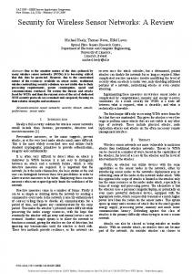
ious software options for wireless sensors are described. An emphasis is placed on embedded engineering analyses, including damage detection algorithms, which have already been embedded in the computational cores of wireless sensors. A true test of a new emerging sensing technology is its performance in the field. The research community has installed wireless structural monitoring systems upon a diverse set of structures to assess the performance of wireless sensors within the complex and challenging field environment. In the literature, a large number of validation tests have been performed on laboratory structures as well as upon bridges, buildings, aircraft, offshore oil platforms, naval ships, among many others. In this paper we provide a detailed description of the current state of experimentation with wireless sensors in the laboratory and the field. We conclude this summary review with our outlook upon the future directions of wireless sensors and sensor networks for SHM. With wireless sensing technology still in its infancy, much work remains for bringing this promising technology to widespread use in all types of structures. In particular, future research studies are needed on challenging issues such as power consumption, time synchronization, multiscale network topologies, decentralized data processing within largescale networks, and formulation of power-efficient data driven usage strategies. 2. Hardware Design of Wireless Sensor Platforms for Structural Health Monitoring The fundamental building block of any wireless sensor network is the wireless sensor. Selection of an appropriate wireless sensor is necessary because the performance of the entire wireless structural monitoring system is dependent upon the individual wireless sensor. As shown in Figure 1, all wireless sensors can generally have their designs delineated into three or four functional subsystems: sensing interface, computational core, wireless transceiver and, for some, an actuation interface. Wireless sensors must contain an interface to which sensing transducers can be connected. The sensing interface is largely responsible for converting the analog output of sen-
sors into a digital representation that can be understood and processed by digital electronics. The quality of the sensor interface is a function of the conversion resolution, sample rate, and number of channels available on its analog-to-digital converter (ADC). Selection of an appropriate sensing interface must be done in consultation with the needs of the monitoring application. For most structural monitoring applications, an analog-to-digital conversion resolution of 16-bits or higher is preferred. Ordinarily, low sampling rates (e.g. less than 500 Hz) are adequate for global-based structural monitoring. However, wireless sensors are increasingly explored for use in acoustic and ultrasonic NDE; as a result, there has been a growing need for higher sampling rates in excess of 500 kHz (Grisso et al., 2005; Lynch 2005). Once measurement data have been collected by the sensing interface, the computational core takes responsibility of the data, where they are stored, processed, and readied for communication. To accomplish these tasks, the computational core is represented by a microcontroller that can store measurement data in random access memory (RAM) and data interrogation programs (such as damage detection routines) in read only memory (ROM). A broad assortment of microcontrollers is commercially available. A major classifier for microcontrollers is the size (in bits) of their internal data bus with most microcontrollers classified as 8-, 16-, or 32-bits. While larger data buses suggest higher processing throughput, both cost and power consumption of these microcontrollers are also higher (Gadre, 2001). An internal element of every microcontroller is a clock. The speed of the clock is a direct measure of how fast embedded programs will be executed by the microcontroller. Again, as the speed of the microcontroller increases, there is a linear increase in power consumed. If the size of the internal RAM and ROM memory is inadequate, additional external memory can be added to the computational core design. To have the capability to interact with other wireless sensors and to transfer data to remote data repositories, a wireless transceiver is an integral element of the wireless sensor design. A radio transceiver is an electrical component that can be used for both the transmission and reception of data. Similar to microcontrollers, a plethora of radios are readily
94
The Shock and Vibration Digest / March 2006
available for integration with a wireless sensor. Thus far, the majority of wireless sensors proposed for use in structural monitoring have operated on unlicensed radio frequencies. In the United States, 900 MHz, 2.4 GHz, and 5.0 GHz, have been designated by the Federal Communications Commission (FCC) as the unlicensed industrial, scientific, and medical (ISM) frequency bands. Many of today’s wireless technologies (e.g. 802.11, Bluetooth, Zigbee) operate on the same set of frequency bands. If a wireless radio operates on the ISM frequencies, the FCC mandates the maximum power an antenna can output is 1W, which effectively limits the transmission range. There exist two types of wireless signals that can be sent upon a selected radio band: narrow-band and spread spectrum signals. Narrow-band wireless transmission modulates all of the data upon a single carrier frequency. Unfortunately, naturally occurring phenomena such as multipath effects and interference can diminish the performance of narrow-band wireless signals (Mittag, 2001). To enhance the reliability of the wireless communication channel, spread spectrum wireless signals are preferred. Spread spectrum encodes data on a number of different frequencies within a frequency band. By effectively spreading the signal energy over a broad spectrum, the probability of interference on the band is greatly reduced (Bensky, 2004). A number of methods for modulating data in a spread spectrum fashion include frequency-hopping spread spectrum (FHSS) and direct-sequence spread spectrum (DSSS). Strong consideration must be given to the communication range of the wireless transceiver. For example, to monitor a large-scale civil structure, communication ranges in excess of 100 m might be necessary, while monitoring an aircraft structure permits the use of shorter range radios. The range of the wireless transceiver is directly correlated to the amount of power the transceiver consumes. As the wireless signal radiates from an antenna in open space, it loses power in proportion to the wavelength of the radio band and inversely proportional to the square of the distance from the transmitter (Rappaport, 2002). A direct result of transmission power reducing inversely proportional to the distance squared is that hopping data across a number of short-range radios is more energy efficient than using a single radio capable of transmitting to longer ranges (Zhao and Guibas, 2004). When radio waves encounter boundaries such as walls and floors, the signal’s power is reduced. Referred to as path loss, the amount of power lost by the wireless signal is dependent upon the material through which the signal must penetrate. A number of researchers have undertaken empirical studies to quantify the propagation distances of wireless signals within structures when communicating on different frequency bands (Seidel and Rappaport, 1992; Davidson and Hill, 1997). Pei et al. (2005) have also measured the range and amount of data loss of different wireless sensors operating on the unlicensed ISM bands in various structural monitoring applications. The last subsystem of a wireless sensor would be the actuation interface. Actuation provides a wireless sensor with the capability to interact directly with the physical system in which it is installed. Actuators and active sensors (e.g. piezoelectric elements) can both be commanded by an actuation interface. The core element of the actuation interface is the digital-toanalog converter (DAC) which converts digital data gener-
ated by the microcontroller into a continuous analog voltage output (which can be used to excite the structure). As simple as a wireless sensor may appear, many challenges are associated with their design and use. In particular, their design requires a rational analysis to determine the trade-off between functionality and power consumption, with functionality often coming at the cost of power. For example, larger communication ranges or greater computational power will result in greater electrical energy consumption by the wireless sensor. Since the integration of wireless communication removes the need for transmitting data from one point to another with cables, the lack of cables requires remote power generation or portable power supplies to be coupled with wireless sensors. Currently, batteries represent the most common portable power source for wireless sensors. However, batteries only contain a finite amount of power; when batteries are exhausted, replacement can be a difficult task, especially when sensors are in locations where human access is limited. In this section, academic and commercial wireless sensor platforms explicitly proposed for use in structural monitoring and SHM systems are chronologically summarized. Tables 1 and 2 provide a comprehensive summary of the performance features of the academic prototypes summarized, while Table 3 summarizes commercial platforms. It should be noted that the summary is not intended to be an exhaustive listing; rather, it highlights the state-of-the-art in wireless sensing up to March 2005. 2.1. Academic Wireless Sensing Unit Prototypes Realizing the need to reduce the costs associated with wired structural monitoring systems, Straser and Kiremidjian (1998) have proposed the design of a low-cost wireless modular monitoring system (WiMMS) for civil structures. Using commercial off-the-shelf (COTS) components, a low-cost wireless sensor approximately 12 × 21 × 10 cm3 is produced. To control the remote wireless sensing unit, the Motorola 68HC11 microprocessor is chosen for its large number of on-chip hardware peripherals and the availability of high-level programming languages (e.g. C) for embedding software. The 68HC11 is mounted upon the New Micros prototyping board NMIT-0022 and features an 8-bit counter, a 16-bit timer, one asynchronous RS-232 serial port, and a 64 kB address space for data and program storage. In order to store embedded firmware for local data processing, 32 kB of additional RAM and 16 kB of additional ROM are included in the design. To achieve reliable wireless communication, a Proxim Proxlink MSU2 wireless modem operating on the 902–928 MHz ISM band is used. Consuming 135 mA of current when communicating, the wireless modem is ordinarily kept in sleep mode where it consumes minimal power (1 mA of current). The maximum open space range of the wireless radio has been determined to be approximately 300 m outdoors, with a maximum data rate of 19.2 kbps. To attain a high degree of reliability in the wireless channel, the Proxlink radio encodes data using a DSSS technique. Finally, to convert analog signals to digital forms, an eight-channel, 16bit, 240 Hz Harris H17188IP sigma-delta ADC is used. An interesting feature of this ADC is its fixed sampling rate (240 Hz). With built-in line noise reduction and support for the Motorola serial peripheral interface (SPI), the Harris
Lynch and Loh / A SUMMARY REVIEW OF WIRELESS SENSORS AND SENSOR NETWORKS
95
Table 1. Summary of academic wireless sensing unit prototypes (1998–2003). Straser and Bennett et Kiremidjian al. (1999) (1998) DATA ACQUISITION SPECIFICATIONS A/D Channels 8 4 Sample Rate 240 Hz A/D Resolution 16-bit 16-bit Digital Inputs
0
Kottapalli et al. (2003)
Lynch et al. (2003a, 2004a, 2004e)
5 20 MHz 8-bit
1 100 kHz 16-bit
0
2
Cygnal 8051
Microchip PIC16F73
Atmel AT90S8515 AVR / MPC555Po werPC 8-bit/32-bit 4 MHz / 20 MHz 8 kB / 26 kB 512 kB / 448 kB
Renesas H8/4069F
ARM7TDMI
8-bit 20 MHz
32-bit
BlueChip RBF915
Proxim RangeLan2
Realtek RTL8019AS
2.4 GHz IEEE 802.15.1 Yes 10 m 10 m
900 MHz
2.4 GHz
Yes 500 m 200 m 10 kbps
Yes 300 m 150 m 1.6 Mbps
50 m 50 m
5x3.8x 1.2 cm 120 mW Battery
10x5 x1.5 cm 100 mW Battery (9V)
12x10x2 cm
30x6x8 cm
Lynch et al. (2001, Mitchell et 2002a, al. (2002) 2002b)
1 100 kHz 16-bit
20 MHz 16-bit
2
EMBEDDED COMPUTING SPECIFICATIONS Processor Motorola Hitachi H8/ Atmel 68HC11 329 AVR8515
Bus Size Clock Speed Program Memory Data Memory
8-bit 2.1 MHz
8-bit 4.9 Hz
8-bit 4 MHz
8-bit
8-bit 20 MHz
16 kB 32 kB
32 kB
8 kB 32 kB
2 kB 128 kB
4 kB 192 kB
WIRELESS CHANNEL SPECIFICATIONS Radio Proxim RadiomeProxLink trix Frequency Band Wireless Standard Spread Spectrum Outdoor Range Enclosed Range Data Rate
900 MHz
Yes 300 m 150 m 19.2 kbps
418 MHz
300 m 40 kbps
FINAL ASSEMBLED UNIT ATTRIBUTES Dimensions 15x13 15D x10 cm x 30 cm Power Power Source Battery Battery (9V) (6V)
Proxim Ericsson RangeLan2 Bluetooth 2.4 GHz
Yes 300 m 150 m 1.6 Mbps
10x10 x5 cm Battery (9V)
ADC is well suited for the wireless sensing unit design; however, it should be noted that no anti-aliasing filter is present. Although the wireless sensor proposed does not emphasize power minimization in its design, the prototype represents the first major step by the structural engineering community towards decentralized data processing and wireless SHM. Bennett et al. (1999) have proposed the design of a wireless sensing unit intended for embedment in flexible asphalt highway surfaces. To record measurement data from two thermometers and two thin-film strain gages, a four-channel sensing interface is designed. While the specific ADC is not mentioned, the resolution of the ADC is 16 bits. To accom-
Battery (9V)
Aoki et al. (2003)
Basheer et al. (2003)
Multiple 10-bit
128 kB 2 MB
Phillips Blueberry Bluetooth 2.4 GHz IEEE 802.15.1 Yes 100 m
2.5x2.5 x2.5 cm Battery
modate the two strain gages, Wheatstone bridge and amplification circuits are designed as part of the wireless sensor’s sensing interface. At the core of the wireless sensor is a Hitachi H8/329 8-bit microcontroller. To provide ample memory for the storage of embedded software that operates the sensor, 32 kB of external ROM is included in the computational core design. To communicate asphalt response data in real time to a data logger, a narrow-band 418 MHz Radiometrix wireless radio is included in the design of the wireless sensor. The Radiometrix radio is capable of data rates of 40 kbps and can communicate to ranges as high as 300 m in open space. The completed wireless sensor prototype is packaged in a water-tight PTFE cylinder with a 15 cm diam-
96
The Shock and Vibration Digest / March 2006
Table 2. Summary of academic wireless sensing unit prototypes (2003–2005). Wang et al. Shinozuka Casciati et Mastro(2003, 2004); (2003); al. (2003b, leon et al. Gu et al. Chung et 2004) (2004) (2004) al. (2004) DATA ACQUISITION SPECIFICATIONS A/D 8 8 5 Channels Sample > 50 Hz 480 Hz Rate 12-bit 12-bit 16-bit A/D Resolution Digital multiple 0 Inputs
4/2
8-bit / 10-bit 2
EMBEDDED COMPUTING SPECIFICATIONS MicroProcessor Analog chip PICDevices micro ADuC832 Bus Size Clock Speed Program Memory Data Memory
8-bit
Ou et al. (2004)
Atmel AVR ATMega 8L
16-bit / 8-bit
8-bit
62 kB
8 kB
2 kB
1 kB
WIRELESS CHANNEL SPECIFICATIONS Radio Aurel XTRLinx BlueChip 915 Technolo- RFB915B gies Frequency 914.5 MHz 916 MHz 900 MHz Band Wireless IEEE Standard 802.15.1 Spread No No Yes Spectrum Outdoor 152 m 200Range 300 m Enclosed 61 m Range Data Rate 100 kbps 33.6 kbps 19.2 kbps
FINAL ASSEMBLED UNIT ATTRIBUTES Dimen8x8x2 cm sions Power Power Battery Source
Chipcon CC1000 2.4 Ghz IEEE 802.11b Yes
433 MHz
Yes (Software)
250 m
76.8 kbps
Farrar et Sazanov et al. al. (2005); Allen (2004) (2005)
6
12-bit
6
4
200 kHz
100 kHz
16-bit
16-bit
16
100/500 Hz 10/12/ 16-bit
Atmel Motorolla Intel Texas AVR 68HC11 Instruments Pentium / MSP430F1611 Motorola ATMega 128 16-bit 16-bit 8-bit 8-bit
16 MB
120/233 MHz 256 MB Compact Flash
8 MHz 128 kB
32 kB
128 kB
32 kB
Chipcon CC2420
Motorola neuRFon
MaxMaxstream Stream 9XCite Xstream 2.4 GHz 2.4 GHz 900 MHz 900 MHz/ 2.4 GHz IEEE 802.15.4 IEEE 802.15.4 Yes Yes Yes Yes 75 m
9.1 m
300 m
9.1 m
100 m
230 kbps
38.4 kbps
250 kbps
10x6x 4 cm 75 mW
eter and 30 cm height. For power, four AA alkaline batteries offering a total voltage of 6 V are included. Recognizing the importance of decentralized data processing in wireless structural monitoring systems, Lynch et al.
Pei et al. (2005)
0
6x9x 3.1 cm Battery + Solar
Wang et al. (2005)
Battery
6W Battery (7.5V)
Battery (9V)
(2001, 2002a, 2002b) have proposed a wireless sensor prototype that emphasizes the design of a powerful computational core. Setting the goal to minimize power consumption throughout the entire sensing unit design, the 8-bit Atmel
Lynch and Loh / A SUMMARY REVIEW OF WIRELESS SENSORS AND SENSOR NETWORKS
97
Table 3. Summary of commercial wireless sensing unit prototypes. UC BerkeleyCrossbow WeC (1999)
UC BerkeleyCrossbow Rene (2000)
UC Berkeley- UC BerkeleyCrossbow Crossbow MICA (2002) MICA2 (2003)
Intel iMote, Kling (2003)
Microstrain, Galbreath et al. (2003)
Rockwell, Agre et al. (1999)
8 1.7 kHz (one channel) 12-bit
4 400 Hz
DATA ACQUISITION SPECIFICATIONS A/D Channels 8 8 Sample Rate 1 kHz 1 kHz
8 1 kHz
8 1 kHz
A/D Resolution
10-bit
10-bit
Atmel ATmega103L 8-bit 4 MHz 128 kB
Atmel ATmega128L 8-bit 7.383 MHz 128 kB
Zeevo ARM7TDMI 32-bit 12 MHz 64 kB
512 kB
512 kB
512 kB
2 MB
128 kB
TR1000
Chipcon CC1000
Wireless BT Zeevo
Conexant RDSSS9M
868 / 916 MHz
315, 433, or 868 / 916MHz
2.4 GHz
RF Monolithics DR3000-1 916.5 MHz
10-bit
10-bit
20-bit
Digital Inputs EMBEDDED COMPUTING SPECIFICATIONS Processor Atmel Atmel AT90LS8535 Atmega163L Bus Size 8-bit 8-bit Clock Speed 4 MHz 4 MHz Program 8 kB 16 kB Memory Data Memory 32 kB 32 kB WIRELESS CHANNEL SPECIFICATIONS Radio TR1000 TR1000
Frequency Band Wireless Standard Spread Spectrum Outdoor Range Enclosed Range Data Rate
868 / 916 MHz 868 / 916 MHz
No
No
No
Yes (Software)
MicroChip Intel StronPIC16F877 gARM 1100 8-bit 32-bit 133 MHz 1 MB
IEEE 802.15.1 Yes
916 MHz
Yes
100 m 10 kbps
10 kbps
FINAL ASSEMBLED UNIT ATTRIBUTES Dimensions 2.5 x 2.5 x 1.3 cm Power 575 mAh 2850 mAh Power Coin Cell Battery (3V) Source
40 kbps
38.4 kbps
600 kbps
75 kbps
100 kbps
7.3 x 7.3 x 8.9 cm 2850 mAh Battery (3V)
AVR AT90S8515 enhanced RISC (reduced instruction set computer) microcontroller is selected. Capable of eight million instructions per second (MIPS), the microcontroller has high computational throughput without consuming large amounts of power. The AVR microcontroller also has a wide variety of on-chip services such as internal oscillators, serial communication transceivers, timers, pulse width modulators (PWMs), and four 8-bit general purpose input/output ports. The microcontroller is able to take full advantage of its 8 kB of programmable flash memory, 512 bytes of SRAM (static random access memory), and 512 bytes of electronically erasable programmable read-only memory (EEPROM) to perform local
1000 mAh Coin Cell
Battery
Battery (3.6V)
Battery (two 9V)
processing and data storage tasks. A low-noise single-channel Texas Instrument 16-bit ADC is used to translate analog signals to a digital format for processing. However, after mounting the ADC within the tailored designed printed circuit board, the authors note that its resolution is reduced to 14 bits due to circuit noise. The high-speed parallel CMOS architecture of the ADC allows the sampling rate to reach 100 kHz. Similar to the unit proposed by Straser and Kiremidjian (1998), the Proxim ProxLink MSU2 wireless modem operating on the 902–928 MHz ISM radio band is integrated with the wireless sensor. In comparison with the wireless sensing unit design proposed by Straser and Kiremidjian
98
The Shock and Vibration Digest / March 2006
Figure 2. Wireless network topologies for wireless sensor networks: (a) star; (b) peer-to-peer; (c) two-tier network topologies.
(1998), the wireless sensor described by Lynch et al. (2001) is compact (10 × 10 × 5 cm3 in size) and relatively low power (250 mW when not transmitting data and 900 mW when using the wireless modem). Mitchell et al. (2002) have proposed a two-tier SHM architecture using wireless sensors (as shown in Figure 2c). Based upon three generations of hardware and software designs, their current wireless monitoring system emphasizes the partitioning of the monitoring system functionality between wireless sensors and wireless data servers (called wireless cluster nodes). In their system, a compact (footprint size of 4 × 7.5 cm2) wireless sensor using a powerful Cygnal 8051F006 microcontroller is proposed for data collection. Capable of 25 MIPS, the microcontroller only consumes 50 mW of battery power and provides 2 kB of RAM for data storage. For communication between wireless sensors and wireless data serv-
ers, an Ericsson Bluetooth wireless transceiver, operating on the 2.4 GHz radio band, is integrated. The communication range of the radio is roughly 10 m line of sight. Provided the short range of the radio, multihopping of data between wireless sensors is proposed. The Bluetooth radio consumes 35 mW of electrical power. After data are collected by the wireless sensors, data can then be transferred wirelessly to wireless data servers (cluster nodes). Each cluster node has both a short-range radio (for communication with wireless sensors in its cluster) as well as a long-range radio (for communication with other remote cluster nodes). The central cluster server is designed to both store and process the vast amounts of data collected from the cluster’s wireless sensors. The cluster node is designed using a single board computer (SBC) running the Microsoft Windows OS. MATLAB is installed in the node for processing
Lynch and Loh / A SUMMARY REVIEW OF WIRELESS SENSORS AND SENSOR NETWORKS
measurement data for signs of structural damage. A key element of this two-tiered wireless SHM system architecture proposed by Mitchell et al. (2002) is its seamless interface to the Internet. Using the World Wide Web (WWW), structural management professionals have the capability to remotely access structural response data, as well as analysis results performed by the monitoring system (Mitchell et al., 2001). The wireless data cluster nodes are equipped with cellular modems for long-range communication (on the order of miles) to a single web server that is accessible from the WWW. Kottapalli et al. (2003) have presented a wireless sensor network architecture that is intended to overcome the major challenges associated with time synchronization and limited power availability in wireless SHM systems powered by batteries. Similar to the two-tiered wireless SHM system proposed by Mitchell et al. (2002), Kottapalli et al. (2003) have proposed a two-tiered wireless sensor network architecture that entails the design of wireless sensing units and local site masters. The role of the sensing unit is to simply collect measurement data and to wirelessly transmit the data to the designated site master. Wireless sensing units communicate with their corresponding site master using the BlueChip EVK915 915 MHz radio transceiver. Using Manchester encoding of the data for wireless transmission, the effective data rate of the radio is 10 kbps. To achieve wireless reliability, each sensing unit communicates directly with its site master by using FHSS encoding. The motivation for selecting this particular radio for inclusion with the wireless sensors is that it is very low power, consuming 36 mW when receiving and 150 mW when transmitting. The embedded microcontroller of the wireless sensing unit prototype is an 8-bit Atmel AVR microcontroller. For data collection, a 16-bit ADC is also included in the unit design. The total power consumption for each individual sensing unit is, on average, 100 mW. Using alkaline AA batteries, this low power demand results in approximately 18 months of battery life before the units deplete the portable energy supply. A network of local site masters forms the upper tier of the sensor network. Their role is to aggregate the data originating from the low-tier wireless sensing units. Each local site master is at the center of a star network topology where wireless sensing units communicate only with their designated site master. As such, the hardware design of the local site master must have ample storage for measurement data and must be cable of high data rate communication. To accomplish these goals, the local site masters are equipped with two radios. The first radio, the BlueChip EVK915, allows the master to communicate with wireless sensing units. A second radio is included, the Proxim RangeLAN2, to facilitate communication between local site masters. The RangeLAN2 operates on the 2.4 GHz ISM band radio, has a data rate of 1.6 Mbps, and can achieve long communication ranges (300 m in open range and 150 m when shielded by heavy construction). The radios are selected to operate on two separate frequency bands in order to minimize interference between site master to site master and site master to wireless sensing unit connections. The RangeLAN2 consumes a large amount of power (800 mW when transmitting or receiving), but it is assumed that the local site masters would be powered by outlet sources. At the core of the local site master is an 8-bit Microchip PIC microcontroller that is employed for data storage and local data processing.
99
While Mitchell et al. (2002) and Kottapalli et al. (2003) have proposed attainment of an overall low-power wireless SHM system by partitioning functionality upon multiple network tiers, Lynch et al. (2003a, 2004a, 2004e) focus upon the design of a low-power but computationally rich wireless sensing unit. In their design, each component of the wireless sensor is selected such that minimal power is required. Often, microcontrollers with high computational throughput consume more energy from portable power supplies compared to simpler microcontrollers. To address this limitation, Lynch et al. (2003a, 2004a, 2004e) have proposed a dual-processor computational core design. Based on their earlier wireless sensing unit design (Lynch et al., 2001), a low-power 8-bit Atmel AVR AT90S8515 microcontroller is utilized for overall unit operation and real-time data acquisition. When data are ready for local processing, the unit turns on the second microcontroller, which is the 32-bit Motorola MPC555 PowerPC. This microcontroller contains 448 kB of ROM, 26 kB of RAM, along with a floating-point arithmetic and logic unit (ALU). At a clock rate of 20 MHz, intensive data processing algorithms, such as embedded damage detection routines stored in ROM, can be executed. When the two microcontrollers are turned on, the AT90S8515 consumes 40 mW of power and the MPC555 (at 20 MHz) consumes 330 mW. In sleep mode, the two microcontrollers both consume 12 mW, respectively. During data collection, measurement data can be stored either in the internal RAM of the microcontrollers or in external memory (512 kB Hitachi HM628512B SRAM). For data collection, a low-power single-channel ADC is included. The Texas Instruments ADS7821 16-bit ADC has a maximum sample rate of 100 kHz and draws 80 mW of power. Included in the sensing interface are two additional channels for external sensors with digital outputs. For wireless communications, the 2.4 GHz Proxim RangeLAN2 radio modem is selected. To supply power to the wireless sensor, a high-energy-density Li/FeS2 7.5 V battery pack is chosen because the estimated duty cycle usage life of the battery in the field is estimated to be of the order of one year (Lynch, 2002). Aoki et al. (2003) have proposed a novel wireless sensing unit prototype, which they call the Remote Intelligent Monitoring System (RIMS). Designed for the purpose of bridge and infrastructure SHM, each hardware component included in their design is carefully chosen to reduce the cost and size of the prototype while achieving adequate performance standards. At the core of the wireless sensor design is the Renesas H8/4069 microcontroller. The microcontroller has a high-speed processing core operating at 20 MHz and an internal 10-bit ADC. Tailored for monitoring dynamic structures, the wireless sensing unit design includes a dedicated three-axis microelectromechanical systems (MEMS) piezoresistive accelerometer (Microstone MA3-04). To enhance the storage capabilities of the wireless sensor design, an additional 2 MB externally interfaced dynamic random access memory (DRAM) is included. The DRAM is employed for storage of time-history data, as well as for performing local computations to minimize the amount of data that need to be transmitted wirelessly. While no details are provided, the RIMS wireless sensor is capable of wireless communication with a remote data repository. The core component of the wireless communication link is the Realtek RTL-8019AS ethernet controller. Embedded within each wireless sensor is an HTTP manager servelet. The embedded HTTP manager allows remote users
100
The Shock and Vibration Digest / March 2006
to interact with sensors and perform tasks remotely by executing suitable servelet functions through the Internet. For instance, users can create documents for unit initialization, to set operational parameters, and to request the display of time-history data, all from a web browser. A more recent version of the RIMS wireless sensor has been proposed with an improved computational core; the Renesas H8 microcontroller is replaced by the Rabbit 3000 microcontroller offering 12-bit analog-to-digital conversion resolution. Casciati et al. (2003b) present the design of a wireless sensing unit intended for SHM of historic landmarks in which wired monitoring systems would be too obtrusive. Again, a two-tier approach to the design of the wireless structural monitoring system is proposed. The authors detail their design of a low-power wireless sensing unit which is situated on the lowest tier of the two-tier monitoring system architecture. Intended to collect structural response measurements from accelerometers, the design of the wireless sensing units is based upon the Analog Devices ADuC812 microsystem. The ADuC812 is a complete data acquisition system-on-a-chip solution that includes an 8051 microcontroller core, 8 kB of flash ROM, an eight-channel 12-bit ADC, and a two-channel 12-bit DAC. The wireless communication subsystem of the wireless sensing unit is based upon the single-channel AUREL XTR-915 RF transceiver operating at 914.5 MHz with a maximum data transmission rate of 100 kbps. Selection of this transceiver is based upon its high transmission rate and low power consumption (160 mW maximum but typically only 120 mW). An important component of the wireless sensing unit design is the inclusion of a third-order low-pass anti-aliasing filter whose pass band is adjustable through the ADuC812 microcontroller. Upon the second tier of the hybrid wireless monitoring system architecture proposed by Casciati et al. (2003b, 2004), are wireless computational units where data streams originating from the lower tier wireless sensing units are aggregated and locally processed. Since the design of the wireless computational unit is not based upon the collection of measurement data from interfaced sensors, the computational units can be placed anywhere, thereby allowing design limitations to be less stringent on weight, dimensions, and power consumption. To establish communication with the wireless sensing units, the wireless computational unit includes the AUREL XTR-915 RF transceiver. For inter-wireless computation unit communication, a second wireless transceiver operating on the 2.4 GHz wireless spectrum is included. The MaxStream 2.4 GHz XStream wireless radio is selected because of the reliability provided by its use of FHSS techniques. The XStream comsumes 750 mW when transmitting and 250 mW when receiving. In addition, the radio can attain a communication range of over 180 m. Basheer et al. (2003) have proposed the design of a wireless sensor whose hardware design has been optimized for collaborative data processing (such as damage detection) between wireless sensors. The wireless sensors proposed form building blocks of a self-organizing sensor network called the Redundant Link Network (RLN). Basheer et al. (2003) call their wireless sensor ISC-iBlue. The design of ISC-iBlue is divided into four main components: communication, processing, sensing, and power subsystems. The processing core of the wireless sensor is designed around the ARM7TDMI microprocessor. Selection of the ARM processor is gov-
erned by the desire to find a processor that is low-power without sacrificing computational throughput; the ARM processor is capable of 100 MIPS. For wireless communication, the Phillips Blueberry 2.4 GHz Bluetooth wireless radio is selected for integration. The Bluetooth radio is both low-power and short-range but employs fast FHSS encoding, thereby enhancing its reliability in the presence of other radios operating on the same frequency. Wang et al. (2003a) have proposed the design of a wireless sensor specifically intended to report displacement and strain readings from a polyvinylidene fluoride (PVDF) thinfilm sensor. Their wireless sensor is similar to that proposed by Casciati et al. (2003b) in that the wireless sensor design is based upon an Analog Devices ADuC832 microsystem. The ADuC832 combines a powerful 8051 microcontroller with a complete data acquisition system on a single integrated circuit chip. To collect data from interfaced sensors (in this case, a PVDF sensor), the ADuC832 provides eight sensing channels serviced by a 12-bit ADC. Also included in the microsystem are two separate 12-bit DACs. Once data are collected, the internal 8-bit 8052 microcontroller is responsible for management of the sensor data. To facilitate the storage and processing of data, the ADuC832 microsystem has 62 kB of ROM reserved for the storage of executable programs and 256 bytes of SRAM for data storage. Integrated with the wireless sensor is a single-channel half-duplex wireless radio operating on the 916 MHz frequency band with a range of 150 m and a data rate of 33.6 kbps (Gu et al., 2004). Extending upon the design of the wireless sensing unit proposed by Kottapalli et al. (2003), Mastroleon et al. (2004) have attained greater power efficiency by upgrading many of the unit’s original hardware components. In particular, the computational core of their unit is designed around a Microchip PICmicro microcontroller. The PICmicro is selected for its low power consumption and high computational performance. The microcontroller is capable of achieving real-time data processing and time synchronization by using multilevel priority interrupts and phase-locked loop (PLL) synchronization units. Moreover, the PICmicro dynamically switches between six power management modes and possesses a failsafe clock monitor to achieve ultralow power consumption. In addition, the availability of self-programming flash memory allows embedded software to be upgraded in the field through the wireless channel. Identical to the unit proposed by Kottapalli et al. (2003), the wireless sensor employs the Bluechip RFB915B RF transceiver for wireless communication. For the sensing interface, the 18-bit Maxim MAX1402 ADC is chosen. The MAX1402 is capable of sample rates as high as 480 Hz and can simultaneously sample sensor data from five channels. Acknowledging the strong dependence upon the ambient temperature of the structure and the accuracy of current damage detection methods, the Maxim DS18S20 digital thermometer is also implemented within the wireless sensing unit design. Drawing from previous experiences with commercial wireless sensor platforms, Ou et al. (2004) have described the design of a new low-power academic wireless sensor prototype for structural monitoring. At the core of their sensor is the low-power Atmel AVR ATmega8L microcontroller. This 8-bit microcontroller has 8 kB of flash memory for storing embedded programs and 1 kB of SRAM for storing measurement data. In total, eight sensing channels are provided
Lynch and Loh / A SUMMARY REVIEW OF WIRELESS SENSORS AND SENSOR NETWORKS
for the interface of sensors. Six of the channels support the conversion from analog sensor outputs into digital formats with resolutions of 8 and 10 bits. The last two channels are for measuring the output of digital sensors such as the Analog Devices ADXL202E MEMS accelerometer. To provide wireless communication between wireless sensors, Ou et al. (2004) integrate the Chipcon CC1000 wireless transceiver. This radio operates on the 433 MHz radio band and can communicate at a data rate of 76.8 kbps. Shinozuka (2003) and Chung et al. (2004a) have described the design of a wireless sensor called DuraNode. Different from the previous wireless sensors that had sensor transparent interfaces, the wireless sensor proposed is designed around two types of MEMS-based accelerometers: Analog Devices ADXL202 and Silicon Design SD1221. While the specific hardware components are not described, the wireless sensor employs a 2.4 GHz 802.11b wireless network interface card as its wireless radio and is powered on lithium–polymer thinfilm battery technology. Recognizing the limitations of battery power, they have also integrated a solar panel with DuraNode to recharge the lithium–polymer battery. The completed DuraNode unit has dimensions of 6 × 9 × 3.1 cm3. In recent years, a new wireless communication standard, IEEE802.15.4, has been developed explicitly for wireless sensor networks (Institute of Electrical and Electronics Engineers, 2003). This wireless standard is intended for use in energyconstrained wireless sensor networks because of its extreme power efficiency. Another important aspect of IEEE802.15.4 is that it offers a standardized wireless interface for wireless sensor networks, thereby ensuring compatibility between wireless sensor platforms with different designs and functionalities. Sazonov et al. (2004) have proposed the design of a low-power wireless sensor around the IEEE802.15.4 wireless standard. For wireless communication, their unit employs the Chipcon CC2420 wireless transceiver. IEEE802.15.4compliant, the radio operates on the 2.4 GHz radio spectrum with a data rate of 250 kbps. The radio has a range of 10–75 m, yet it only consumes 60 mW when receiving and 52 mW when transmitting. To design the remainder of the wireless sensor hardware to be as low power as possible, the 16-bit Texas Instruments MSP430 microcontroller is selected for the computational core. The MSP430 provides the wireless sensing unit with a six-channel 12-bit ADC and a twochannel 12-bit DAC. With 2 MB of non-volatile EEPROM, the MSP430 is capable of storing sophisticated data interrogation algorithms. When fully assembled, the proposed lowpower wireless sensor is intended to serve as the building block of a wireless intelligent sensor and actuator network (WISAN). The previously described wireless sensor designs seek to minimize power consumption simultaneous to maximizing functionality. Allen (2004) and Farrar et al. (2005) have proposed a different design strategy; the emphasis of their wireless sensor design is on providing ample computational power to perform a broad array of damage detection algorithms within a wireless SHM system. In close collaboration with Motorola Labs, Farrar et al. (2005) have described the design of a wireless sensor designed to have seamless interaction with DIAMOND II, an existing damage detection package written in Java. As such, the overall design of the wireless sensor is based on the powerful computational core needed to execute DIAMOND II-based damage detection routines.
101
Instead of a low-power microcontroller, the wireless sensor is designed using a standard PC-104 SBC with a 133 MHz Pentium processor, 256 MB of RAM, and a 512 MB Compact Flash (CF) card serving as a hard drive. Other features included on the SBC are serial, Ethernet, and USB interfaces for communication with peripherals. To provide the wireless sensor with the capability to interface with sensors, a separate sensing board is designed. The sensing board houses a Motorola DSP56858 digital signal processor (DSP) that is used to sample data from six single-channel Maxim ADCs. The maximum rate for simultaneously sampling the six ADCs is 200 Hz. After data are collected by the sensing board, they can be forwarded to the SBC through the serial port. Finally, a Motorola neuRFon transmission board utilizing the IEEE802.15.4 wireless sensor communication standard is selected. The IEEE802.15.4 transceiver operates on the 2.4 GHz ISM radio band with a data rate of 230 kbps and an indoor range of 10 m. When fully 3 packaged, the total unit volume is 1750 cm and consumes 6 W of power. The wireless sensor platform proposed by Allen (2004) and Farrar et al. (2005) is called Husky. Using the latest commercially available embedded system components, Wang et al. (2005) have proposed a wireless sensing unit with multitasking capabilities. In particular, a lowpower wireless sensor that can sample measurement data simultaneous to wirelessly transmitting data with other wireless devices is proposed. For the sensing interface, a fourchannel Texas Instrument ADS8341 16-bit ADC is selected to convert analog sensor signals to digital formats for use by the microcontroller. This ADC is selected for its low power consumption and high sample rates (100 kHz maximum). For the computational core, the low-power 8-bit Atmel ATmega128 AVR microcontroller is selected. The microcontroller has 128 kB of ROM, which is sufficient for storing damage detection software. In addition to ROM, 4 kB of SRAM is integrated with the microcontroller; however, this amount of SRAM is insufficient to store all the collected data. An additional 128 kB of SRAM (Cypress CY62128B) is interfaced with the microcontroller for the storage of measurement data. The most attractive feature of the wireless sensing unit design is its wireless radio. With the wireless radio identified as one of the most power hungry elements of a wireless sensor design, Wang et al. (2005) have proposed the integration of the MaxStream 9XCite wireless modem. This radio operates on the 900 MHz radio band and is capable of data rates as high as 38.4 kbps. The communication range of the radio is 300 m line-of-sight yet the radio only consumes 250 mW when transmitting, 150 mW when receiving, and less than 5 mW when idle. With efforts to further reduce the size of the wireless sensor, the electrical circuit is printed on a com2 pact two-layer circuit board (9.7 × 6 cm ). When fully assembled, the wireless sensor is 10 × 6.5 × 4 cm3 and is powered by five AA batteries. Undertaking a much broader study, Pei et al. (2005) have rigorously evaluated the impact different hardware components have on the quality of data collected by wireless sensors. To facilitate such an evaluation, a highly modular wireless sensor architecture, in which different hardware components can be readily interchanged, is proposed. Some of the hardware components that can be interchanged include the wireless sensor’s ADC, interfaced sensors, and wireless transceivers. The common element to all of the hardware permutations is the computational core. The wireless sensor architecture pro-
102
The Shock and Vibration Digest / March 2006
posed is based upon the Motorola 68HC11 microcontroller, which is a popular microcontroller with 32 kB of SRAM and 32 kB of ROM. The first hardware element evaluated is the ADC. In total, three different ADCs with varying resolutions (10-, 12-, and 16-bits) are interfaced with the wireless sensor design. To facilitate the change of the ADC, all three are selected to have the same interface with the microcontroller. Included with each ADC is a four-pole Butterworth low-pass anti-aliasing filter (LPF) with a cutoff frequency of 35 Hz. Also of interest in their study is the impact of the wireless transceiver carrier frequency on both the range and the reliability of the wireless communication channel. The MaxStream XStream wireless transceiver is selected for integration within the modular wireless sensor architecture. The XStream is a FHSS radio that has impressive range. The authors evaluate two variations of the XStream radio: one operating at 900 MHz and another at 2.4 GHz. When operated at 900 MHz, the radio is capable of communication ranges of up to 450 m, while at 2.4 GHz, its range is 180 m. As part of the study, the ranges of the radios, as well as the number of data packets lost, are quantified when the sensors are installed at a variety of locations in typical structural environments. Figure 3 presents many of the academic and commercial wireless sensors described in this summary review. The academic prototypes presented include the wireless sensor prototypes proposed by Straser and Kiremidjian (1998), Lynch (2002), Aoki et al. (2003), Allen (2004), and Wang et al. (2005). 2.2. Commercial Wireless Sensor Platforms A number of commercial wireless sensor platforms have emerged in recent years that are well suited for use in SHM applications. The advantages associated with employing a commercial wireless sensor system include immediate outof-the-box operation, availability of technical support from the platform manufacturer, and low unit costs. For this reason, many academic and industrial research teams have begun to explore these generic wireless sensors for use within SHM systems. In particular, the structural engineering community has focused their attention on the Mote wireless sensor platform initially developed at the University of California-Berkeley and subsequently commercialized by Crossbow (http://www. xbow.com/) (Zhao and Guibas, 2004). A major reason for the Motes’ popularity is that it is an open source wireless sensor platform with both its hardware and software (TinyOS) design available to the public. Since their introduction, Motes have been deployed in a number of large-scale monitoring applications. For example, over 150 Motes have been deployed to monitor the weather and nesting conditions of birds on Great Duck Island, Maine (Kumagai, 2004). Recently, Intel has produced its own version of the Mote called iMote (Kling, 2003). Well over 70 iMotes have been deployed by Intel to monitor the performance and health of pumps and motors in one of their microchip factories (Culler and Mulder, 2004). A number of other commercial wireless sensor platforms have been used for structural monitoring in addition to the Motes, including platforms from Ember (http://www.ember.com/), Microstrain (http://www.microstrain.com/), and Sensametrics (http://www. sensametrics.com/). In contrast to the Motes, these wireless sensor platforms are proprietary and not open source. The Crossbow MICA2 and Intel iMote wireless sensors are pre-
sented in Figure 4. The commercial platforms to be described in this section are summarized in Table 3. The Berkeley Mote platform has been under development since the late 1990s with the first prototype, called WeC, produced in 1999 and commercialized as the Rene Mote by Crossbow. The WeC hardware is based upon the 8-bit Atmel AT90LS8535 AVR microcontroller for its computational core. The internal eight-channel, 10-bit ADC of the microcontroller serves as the primary sensing interface capable of sampling rates as high as 1 kHz. With only 8 kB of ROM and 512 Bytes of RAM included in the microcontroller, an additional 32 kB of external RAM is included with the WeC platform. To establish wireless communication with other wireless sensors, the RF Monolithics TR1000 wireless radio is integrated. This single-channel TR1000 transceiver operates on the 916 MHz frequency, employs amplitude modulation (AM), and communicates with a data rate of 10 kbps (Maurer, 2003). Hill and Culler (2002) report the motivation for selecting the TR1000 is due to it consuming only 15 mW of battery energy with a maximum communication range of 60 m. In 2001, the WeC wireless sensor was then modified to produce the Rene2 platform. The Rene2 Mote has an identical design to the WeC except that the original microcontroller is replaced with the Atmel ATmega163L (Maurer, 2003). The ATmega163L has larger internal memory banks including 16 kB of ROM and 1 kB of RAM. Tanner et al. (2002, 2003) have presented the adoption of the Crossbow Rene2 Mote in a SHM system. During this study, the authors report their experience of interfacing two types of MEMS accelerometers with the Mote: the Analog Devices ADXL202 and Silicon Devices SD-1221. While interfacing the accelerometers to the microcontroller’s 10-bit ADC, it is discovered that two sensing channels cannot be sampled simultaneously, resulting in a relative offset of 30 µs between samples. This offset negatively impacts the accuracy of embedded software used to calculate cross-correlation coefficients for sensor signals with high-frequency content. The small amount of on-board RAM does not permit large buffers of sensor data to be stored. As a result, only on-thefly type embedded data interrogation algorithms have been successfully embedded in the Mote’s computational core for local data processing. A useful feature of the Mote is its threecolor light emitting diode (LED) display. The authors report the use of the three-color LED as an indicator of the degree of calculated damage based on embedded damage detection algorithms: red corresponds to severe damage, yellow corresponds to the onset of damage, and green corresponds to the structure being undamaged. Glaser (2004) has evaluated the suitability of the hardware elements of the Crossbow Rene Mote during monitoring studies performed in the laboratory and field. After using the Rene Mote in their studies, some issues were identified with its hardware design. In particular, problems were reported with the reliability of the single-channel RF Monolithics TR1000 wireless radio. During testing, the radios experience significant communication interference, resulting in the loss of sensor data wirelessly communicated. The reliability of the radio is further reduced in the presence of other electronic equipment including cameras, cell phones, and radios. Short of these limitations, the conclusion of the study is that the concept of affordable wireless monitoring systems is successfully established.
Lynch and Loh / A SUMMARY REVIEW OF WIRELESS SENSORS AND SENSOR NETWORKS
103
Figure 3. Academic wireless sensor prototypes: (a) WiMMS wireless sensor (Straser and Kiremidjian, 1998); (b) dual-core prototype by Lynch (2002); (c) RIMS wireless sensor based on Aoki et al. (2003); (d) Husky wireless sensor (Allen, 2004; courtesy of Motorola Labs); (e) wireless sensor prototype by Wang et al. (2005).
104
The Shock and Vibration Digest / March 2006
Figure 4. Commercial wireless sensors: (a) Crossbow MICA2 Mote; (b) Intel iMote.
To provide more program and data storage and to improve the flexibility of the wireless communication channel, Crossbow released the MICA Mote wireless sensor in early 2002 as the successor to the Rene2. The computational core of the MICA is based on the 8-bit Atmel ATmega103L microcontroller (Maurer 2003). The ATmega103L is selected for the MICA core because of its considerable internal flash ROM (128 kB) and RAM (4 kB) banks that facilitate the storage of an embedded OS called TinyOS. Again, the internal eightchannel 10-bit ADC of the microcontroller is utilized as the primary sensing interface for the MICA Mote. This ADC is capable of sample rates up to 1 kHz. To provide additional memory for the microcontroller, 512 kB of non-volatile memory is included off-chip in the MICA hardware design. Similar to the WeC and Rene platforms, the MICA utilizes the single-channel amplitude modulation TR1000 wireless transceiver. To conserve power for long-term field deployment, the MICA Motes utilize three different power modes: idle, power down, and power save. In total, the sensing unit can operate for approximately 30 h on two AA batteries. Ruiz-Sandoval et al. (2003) have reported their experiences using the MICA Mote wireless sensing platform for structural monitoring. Their study utilizes the Crossbow MTS310CA sensor board, which includes light, temperature, acoustic, and magnetic sensors along with an Analog Devices ADXL202E accelerometer. The MTS310CA sensor board plugs directly to a multipin header situated on the MICA printed circuit board. The performance of the ADXL202E accelerometer in tracking the motion of a shaking table is compared to that of a PCB393B04 accelerometer attached to a tethered laboratory data acquisition system. While the time histories provided by both accelerometers look identical, transformation to the frequency domain reveals an excessive noise floor of the ADXL202E, hampering the accuracy of the sensor for signals below 1.5 Hz. To address these limitations, RuizSandoval (2004) has proposed a new sensor board to replace the MTS310CA. Called the Tadeo sensor board, the board is designed with the low-noise Silicon Devices SD1221 MEMS
accelerometer. In the frequency domain, the SD1221 accelerometer is consistent with the PCB393B04 accelerometer, especially below 1.5 Hz. Based on extensive experience using the MICA and MICA2 platforms, Spencer (2003) has identified critical hardware issues that must be addressed before the MICA Motes can be used for SHM. In order to achieve sufficient measurement fidelity when using wireless sensors, the 10-bit ADC resolution must be improved. Also, time synchronization across a large number of MICA Motes has been found to be challenging with synchronization errors of 7 ms encountered. In 2003, the MICA was modified to improve the reliability of the communication channel. With the original TR1000 single-channel radio susceptible to interference and data loss, the MICA2 was introduced with a new radio offering greater reliability. The Chipcon CC1000 wireless transceiver operates on the 900 MHz radio band and is a frequency modulation (FM) radio with excellent noise immunity. The carrier frequency of the CC1000 can be changed in software, allowing FHSS encoding techniques to be employed with the radio. The data rate of the CC1000 is reported as 38.4 kbps (Maurer, 2003). Like the radio, the ATmega103L microcontroller is replaced with the Atmel ATmega128L. The ATmega128L has the same amount of on-chip memory (128 kB ROM and 4 kB RAM). Recently, the MICA2 has been upgraded with a 2.4 GHz IEEE802.15.4 compliant wireless transceiver and is called the MICAz (Crossbow, 2004). Finally, the most significant change in the new MICA2 and MICAz designs is the size reduction of the processor boards. For the MICA2 and 3 MICAz, the total unit size is approximately 6 × 3 × 1 cm . A number of researchers adopt the improved MICA2 Mote in their research. Kurata et al. (2003a, 2003b) have reported on their use of the MICA2 to monitor the response of a laboratory structure excited by a shaking table. The Tadeo sensor board initially proposed by Ruiz-Sandoval (2004) is interfaced to the MICA2 to measure the acceleration response of the structure. While the MICA2 has an improved radio with frequency hopping spread spectrum (FHSS) encoding, some
Lynch and Loh / A SUMMARY REVIEW OF WIRELESS SENSORS AND SENSOR NETWORKS
data loss is still experienced during testing. Ou and Li (2003) report similar results having used MICA2 Motes on various laboratory structures. Since the MICA2 Mote is unable to measure structural strain, Nagayama et al. (2004) implement a new integrated strain sensor board for the MICA2 Mote that accommodates strain gages. To be useful for structural monitoring applications, a sensor board capable of measuring strains spanning from 1 to 2000 microstrains is designed and validated. At the center of the sensor board is a standard Wheatstone bridge circuit tailored for high resistance strain gages. The decision to design the sensor board for a 4.5 kΩ strain gage is to limit the power consumed from the MICA2 batteries during operation of the strain gage circuit. To ensure low levels of strain are measurable by the strain sensor board, a four-pole Butterworth low-pass filter with a high signal-to-noise ratio is designed to remove high-frequency noise. The output of the Wheatstone bridge is amplified using an Analog Devices AD623 low-noise amplifier. The role of the amplifier is to overcome the low 10-bit resolution of the MICA2’s ADC. Pakzad and Fenves (2004) describe a study where a novel prototype accelerometer sensor board is integrated with a MICA2. With the standard Mote sensor board (MTS310CA) poorly suited for structural monitoring, the sensor board proposed by Pakzad and Fenves (2004) is intended for use in SHM applications. Upon the sensor board are four accelerometer channels: two orthogonal channels are provided by a single Analog Devices ADXL202 MEMS accelerometer while two Silicon Design SD1221 single-axis accelerometers are oriented parallel to the two-axes of the ADXL202. The Silicon Design SD1221 accelerometers have noise floors of 30 µg which allow them to measure small amplitude structural vibrations. Static and dynamic laboratory testing are performed using the sensor board in order to assess its noise floor and frequency performance. First, the accelerometers are tested in a seismically isolated vault in a static condition to confirm the accelerometer noise floor. While the SD1221 is able to achieve its specified noise floor (the measured noise floor was 32 µg), a slow varying drift was reported in the sensor output observed over 30 min. The source of the drift is identified as temperature-dependent, thereby suggesting temperature compensation is needed for the accelerometer. The accelerometers are also tested using a low-noise vertical shaking table. As expected, the SD1221 accelerometer outperforms the ADXL202 during these dynamic tests. In particular, the high noise floor of the ADXL202 results in loss of measurement accuracy at low frequencies (0–0.3 Hz) as compared to the SD1221. Close research collaboration between the University of California-Berkeley and the Intel Research Berkeley Laboratory has resulted in a next-generation Mote platform called iMote. As developed by Kling (2003), the hardware design of the iMote is different from those of the MICA, MICA2, and MICAz Motes. Recognizing that the sensing application drives the choice for the appropriate sensing interface, the iMote is designed with only a computational core and wireless transceiver. iMotes employ a highly modular construction allowing sensing interfaces fabricated as separate boards to be snapped onto the iMote circuit board. At the core of the iMote is the 32-bit ARM7TDMI microcontroller operating at 12 MHz. This processor selection provides four times greater computational power than the previously mentioned MICA
105
Motes. Coupled within the microcontroller is 64 kB of RAM intended for data storage and 512 kB of ROM for running the embedded OS, TinyOS. On the wireless communication end, the 2.4 GHz Zeevo Bluetooth radio is integrated with the ARM7TDMI microcontroller on a single integrated circuit chip. Selection of Bluetooth for wireless communication between iMotes is motivated by its high data rate (720 kbps) and high reliability (FHSS). Moreover, the Bluetooth media access control (MAC) protocol allows the iMotes wireless sensor network to be both scalable and reliable. The iMote is very compact with dimensions of 3.5 × 3.5 × 2.5 cm3 and is powered by two Panasonic Lithium CR2 3V batteries. Spencer et al. (2004) have reported on the availability of the Intel iMote platform which will potentially serve as a powerful tool for future wireless SHM systems. Aside from the open-source efforts by researchers at the University of California-Berkeley, Crossbow, and Intel, other commercially available wireless sensor platforms have been adopted for SHM. For example, researchers at the Rockwell Science Center propose the design of a wireless sensing unit designed for military applications which could potentially include structural monitoring. The defining feature of the wireless sensor platform proposed by Agre et al. (1999) is its ability to self-organize when deployed in the field. The wireless sensor prototype, called AWAIRS, adopts the powerful 32bit Intel StrongARM 1110 microcontroller for its computational core. This microcontroller includes 128 kB of SRAM and over 1 MB in flash ROM for embedded software storage. The typical power consumption of the StrongARM 1110 is approximately 200 mW; however, when placed in sleep mode, the microcontroller only consumes 0.8 mW. To collect data from a variety of sensors, including geophones, acoustic sensors, magnetometers, and accelerometers, a 20-bit Analog Devices AD7714 ADC is adopted. Using a standard serial peripheral interface, the StrongARM microcontroller is capable of commanding the ADC to collect measurement data at sample rates as high as 400 Hz. To render networks of AWAIRS wireless sensors self-organizing, Agre et al. (1999) have been careful in selecting a suitable wireless radio for their prototype. The Conexant RDSSS9M wireless cordless telephone radio is selected for integration with AWAIRS. The 900 MHz radio employs spread spectrum encoding with data rates as high as 100 kbps. The communication range of the radio is well over 100 m. When fully assembled, AWAIRS is only 7.3 × 7.3 × 8.9 cm3 in dimension and is powered by two 9 V alkaline batteries. A wireless structural monitoring system proposed by researchers at MicroStrain is assembled from off-the-shelf electrical components resulting in a functionally rich platform (Townsend et al., 2002). At the core of the wireless sensor node is the 8-bit Microchip PIC16C microcontroller where embedded software is stored in the microcontroller’s internal electrically erasable, programmable, read-only memory (EEPROM). To allow for the interfacing of various sensors to the node, the Analog Devices AD7714 16-bit ADC is included in the node design. An attractive feature of the AD7714 ADC is a programmable voltage gain on the sensor inputs ranging from 1 to 128. To achieve wireless communication back to a remote data repository, a surface acoustic wave (SAW) radio operating on the 418 MHz frequency is selected. To modulate digital data upon the selected carrier frequency, the frequency shift keyed (FSK) pulse code mod-
106
The Shock and Vibration Digest / March 2006
ulation method is employed. This pulse code modulation technique permits the wireless nodes to detect errors in the wireless communication channel, thereby increasing the reliability of the radio. When fully assembled, the wireless node is 9 × 6.5 × 2.5 cm3 and is powered by two 1.5 V (3 V total) lithium–ion batteries. Arms et al. (2004) have reported a more recent improvement on the original wireless sensor proposed by Townsend et al. (2002). The SAW wireless radio originally integrated with the wireless sensor represents a poor utilization of the wireless channel since only one sensor node can communicate at any one point in time. Instead, Arms et al. (2004) propose the integration of the Chipcon CC1021 wireless transceiver with the wireless node. Operating on the 900 MHz radio band, multiple nodes can utilize the same wireless bandwidth through frequency division multiple access (FDMA) methods. In stark contrast to the original time division multiple access (TDMA) methods, the new radio allows 26 wireless sensors to communicate simultaneously on the 26 individual frequencies equally distributed from 902 to 928 MHz. In addition to improving the radio, the new wireless sensor proposed by Arms et al. (2004) also includes 2 MB of on-board RAM for data storage. 3. Embedded Software for Wireless Sensors The integration of mobile computing with wireless sensors represents a major paradigm shift in the design and use of structural monitoring systems. To take full advantage of the computing power, integrated, embedded software is needed to automate wireless sensor operations and to process structural response data. Embedded software for wireless sensors is often structured as hierarchal layers (Hayes, 2001; Morton, 2001). At the lowest layer is the OS whose role is to hide implementation details of the underlying wireless sensor hardware from upper software layers. Above the OS are layers of software dedicated to operating the wireless sensor (e.g. collect data, store data, communicate with other sensors) and for the execution of embedded data interrogation methods (e.g. damage detection algorithms). As wireless sensors continue to shrink in size and cost, the demand for dense networks of wireless sensors in SHM applications will continue to grow. A significant amount of engineering has gone into the design of wireless sensors to ensure they can be deployed in large numbers. For example, high data rate radios employing FHSS encoding allow multiple wireless sensors to simultaneously share a common wireless channel. Furthermore, the absence of cables enforcing a static network topology allows wireless sensor networks to form ad hoc topologies built upon simple peer-topeer connectivity. The embedded OS is responsible for managing the operation of hardware and to form effective network topologies. With a robust OS in place, engineers can focus their energies upon the coding of interrogation algorithms. To date, engineering algorithms explored for embedment in wireless sensors have been from the system identification and damage detection fields. In this section we outline some of the field’s major accomplishments in writing embedded interrogation software for wireless sensors deployed for SHM.
3.1. Embedded Operating Systems TinyOS, developed by researchers at the University of California-Berkeley in collaboration with the Intel Research Berkeley Laboratory, is one of the most widely utilized OSs for deeply embedded wireless sensor networks. While TinyOS is not dedicated to any one wireless sensor platform, it is the default OS embedded in the computing cores of the various Crossbow and Intel Motes. A distinct advantage of TinyOS is that it is an open-source OS readily available to the public for free use and modification. Researchers such as Tanner et al. (2003), Glaser (2004), and Kurata et al. (2004) have all utilized the functionality of TinyOS to perform their laboratorybased structural monitoring experiments using Motes. As described by Hill (2000), TinyOS is intended to maximize the potential of the limited resources available on wireless sensors to achieve a functional wireless sensor network. Specifically, TinyOS is intended to render wireless sensors defined by short communication ranges both scalable and energy-efficient. In addition, the limited amount of program memory often found on wireless sensors necessitates the OS to be as small as possible; TinyOS is designed to occupy only 256 bytes of RAM and 4 kB of ROM. TinyOS is written in the high-level programming language NesC, which is based upon the C programming language. Included in TinyOS are basic services such as data collection from interfaced sensors, processing of sensor signals, and utilization of the radio for communication with other wireless sensors. To extend the service life of wireless sensors powered by portable batteries, numerous low-power modes of operation are included in the OS (see http://www.tinyos.net/). TinyOS distinguishes itself from other OSs by its explicit support of ad hoc networking and multihop data transmission (see http://www.tinyos.net/). When the communication range of two wireless sensors is shorter than their physical separation, connectivity can still be established by multihopping. Multihopping is defined as the retransmission of data by intermediate wireless sensors so that data arrive at the final intended wireless sensor (or base station). Even though many wireless sensors are required for the transmission of data in the wireless network, multihopping is more energyefficient than having longer-range radios which offer direct connectivity between all sensors (Zhao and Guibas, 2004). TinyOS offers multihopping connectivity by autonomously routing all communication packets through the wireless sensor network based upon ad hoc peer-to-peer connections. When a wireless sensor is ready to send data, TinyOS calls the RouteSelector function to recommend an optimal multihop route for the packet through the network. To find the optimal path, the RouteSelector function calls estimator subfunctions that determine the link quality between wireless sensors, geographical position estimates, and power estimates to recommend a multihop data route with the highest link quality and lowest power consumption. With every wireless sensor playing an important role in the communication network, the embedded OS must be capable of concurrent operation. Concurrency allows wireless sensors to perform local tasks such as data processing, while simultaneously participating in network communication tasks. To allow TinyOS to handle communication tasks quickly and asynchronously, a scheduler is included in the OS to prioritize the servicing of requested services. To ensure no wire-
Lynch and Loh / A SUMMARY REVIEW OF WIRELESS SENSORS AND SENSOR NETWORKS
less sensor reduces the performance of the global wireless sensor network, high priority tasks (e.g. multihop communications) interrupt lower priority tasks (e.g. data processing). While TinyOS has gained popularity due to its embedment in the Mote platform, researchers have developed OSs for their own academic prototype wireless sensors. Lynch et al. (2004a) have described a two-layer embedded software architecture intended for local data interrogation by wireless sensors including damage detection. The first layer of the embedded software acts as a single-thread OS that hides the details of the underlying hardware from the upper software layer. The OS is written in a modular fashion to encapsulate the functionality of various subsystems of the wireless sensor including the sensing interface and the wireless communication channel. Working closely at the hardware level, there are six software modules written in C and embedded in the computational core to control the key hardware components of the wireless sensing unit hardware. The first module operates the serial port (UART) of the microcontroller for operation of the wireless radio. The second and third modules operate the RangeLAN2 wireless modem by implementing the modem’s communication protocols. To translate analog sensor signals into digital formats upon a precisely timed schedule, a fourth module operates the wireless sensor ADC in real time. The fifth software module performs efficient storage of sensor data within on-board memory. The module organizes memory as two data stacks; two stacks permit data to be buffered in one stack while the wireless radio transmits sensor data from the second stack. The final module is to take measurements from digital sensors interfaced to the wireless sensor’s two digital sensor channels. Most recently, Wang et al. (2005) have undertaken a redesign of the original OS proposed by Lynch et al. (2004a). Their new design allows for multiple threads to be executed at the same time. This permits wireless sensors to simultaneously collect measurement data and wirelessly transmit the data, all in real time. In addition, features are added to the OS including high-precision clock synchronization across the network. 3.2. Embedded Engineering Analyses for Structural Health Monitoring What distinguishes wireless sensor networks from traditional tethered structural monitoring systems is the collocation of computing power with the sensor. This embedded computing power can be utilized by the wireless sensor to self-interrogate structural response measurements it has collected. In contrast to a tethered structural monitoring system, the wireless sensing infrastructure can be utilized for in-network processing of response data for detection of structural damage. Autonomous execution of damage detection algorithms by the wireless sensor represents an important step towards automated SHM. However, allowing sensors to interrogate their own data has many other benefits. For example, as the cost and size of wireless sensors drastically reduce, hundreds of sensors could be installed in a single structure. Such a scenario would result in a centralized data repository being inundated with measurement data it must collect. Therefore, in-network processing of measurement data can be seen as a means of minimizing data glut in the monitoring system. Furthermore, the wireless radios integrated with the wireless
107
sensors generally consume the greatest amount of energy from portable batteries. As a means of preserving battery life, local data processing is significantly more energy efficient than transmitting raw time-history data via the wireless communication channel. Straser and Kiremidjian (1998) were the first to describe algorithms for determining the health of a civil structure using wireless sensors. Their method is to detect the general structural state immediately following a seismic event. At the core of their embedded analysis is the use of the normalized Arias intensity (Arias, 1970). As an indirect measure of a structure’s kinetic energy, the method can be used to detect when energy is dissipated by the structure during the formation of damage. Essentially summing the square of the structural acceleration measured over the earthquake duration, this decentralized damage detection method is easy to calculate within a wireless sensor’s microcontroller. The Cooley–Tukey implementation of the fast Fourier transform (FFT) is successfully embedded in the computational core of a wireless sensing unit by Lynch et al. (2003a). The FFT embedded in the wireless sensing unit is utilized during field deployments of the wireless monitoring system to provide the frequency response functions (FRFs) of instrumented structures. The accuracy of the complex-valued Fourier amplitude spectra calculated by the wireless sensor is compared to that determined by MATLAB using the same time-history data. The wireless sensor is shown to provide identical results compared to those generated by MATLAB (Lynch, 2002). While many researchers have proposed the use of modal frequencies as a primary damage indicator, the method lacks sensitivity in structures where environmental factors also contribute to modal frequency shifts (Doebling et al., 1996). To fully account for the environmental and operational variability of structures, a damage detection methodology based upon a pattern recognition framework is proposed by Sohn and Farrar (2001). Their method begins with the stationary response time history of the structure at a single measurement location. Using these data, an autoregressive (AR) time series model is fit to the data. The residual error of the fitted AR time series model and the structural output are then used to fit a second autoregressive with exogenous input (ARX) time series model. The final residual error of the ARX model is identified as the damage sensitive feature of the proposed method. To accommodate for environmental variability, AR– ARX time series models are determined for the structure in its undamaged state when exposed to different operational conditions. These AR–ARX time series models form a library of baseline models describing the structure in its undamaged state. When the structural response is taken from the structure in an unknown state (damage or undamaged), an AR–ARX time series pair is fitted to the data. The coefficients of this AR– ARX model pair are then compared to the library of AR– ARX coefficients corresponding to the undamaged structure. The undamaged AR–ARX model pair closest (based on the Euclidian distance of the AR coefficients) to that of the AR– ARX coefficients of the unknown structure is selected from the library. If the structure in the unknown state is not damaged, then the AR–ARX model pair corresponding to the undamaged structure will fit the response data of the unknown structure well. If the AR–ARX model pair selected from the database does not fit the data well, then the structure is iden-
108
The Shock and Vibration Digest / March 2006
tified as damaged. The metric for determining the quality of the model fit is the standard deviation of the ARX model residual error; damage is concluded when the ARX error standard deviation is above an established threshold. The proposed AR–ARX time series method of damage detection has two attractive features: it is inherently decentralized by determining damage in the vicinity of a single measurement location, and it does not consume significant computational resources. For these two reasons, Lynch et al. (2004d) propose embedding the complete AR–ARX time series method of damage detection in a wireless sensing unit for autonomous execution. The methodology allows sensor nodes to be computationally independent so that they can collect raw time-history records and generate results without nodeto-node interaction or the exchange of time-history data. As described by Lynch et al. (2003d), the coefficients of the AR model are calculated by a wireless sensing unit using Burg’s method to solving the Yule–Walker equations. Burg’s method offers many advantages over the least-squares solution to the Yule–Walker equations, including stability and accuracy. The implemented method uses the wireless sensors to determine the AR coefficients while AR coefficients are wirelessly transmitted to a centralized data repository where the AR–ARX model pairs for the undamaged structure are stored. Once the closest AR–ARX model is selected from the undamaged library, the coefficients of the undamaged AR–ARX time series models are transmitted back to the wireless sensor where the residual error of the ARX model is found using the original response time history. The standard deviation of the residual error is then checked by the wireless sensor to see if it has exceeded an established threshold that defines the structure as damaged in the vicinity of the measurement point. Caffrey et al. (2004) propose a decentralized method of detecting damage using a network of Motes installed in a structural system. Recognizing the transmission of sensor time histories as a wasteful use of the Motes’ batteries, they propose each wireless sensor to calculate the Fourier spectra of structural acceleration time histories so that modal frequencies and the signal energy contained in each corresponding mode can be determined. After the modal frequencies and modal signal energy contributions are calculated at each sensor location, they are wirelessly transferred to a centralized data repository. The data repository is then given the task of assessing changes in modal frequencies and signal energy contributions to diagnose damage. To validate the proposed damage detection methodology, a laboratory-based study is performed with the IASC–ASCE Structural Health Monitoring Benchmark Structure (Johnson et al., 2004). Different combinations of sensors and actuators are employed to actuate and to gather the corresponding structural response. By using a total of 360 different damage patterns, the proposed algorithm is adequate for detecting damage, especially when a dense sensor network with multiple actuators to induce forced excitations on the structure is present. To illustrate the ability of wireless sensors to monitor the health of structures based upon the response of individual structural elements (e.g. columns, beams, joints), Lynch et al. (2004e) have presented the embedment of a local-based damage detection method based upon damage index models. The damage index method proposed is intended for use in structures constructed of cementitious materials that are exposed to cyclic loadings, such as those encountered during seismic
events. The damage index method, modified from a damage index model initially proposed by Kratzig et al. (1989), considers the peak response of a structural element in the time domain. Using only the response peaks, the damage index model calculates an index that falls between 0 and 1. When the index is 0, the element is in its uncracked virgin state. In contrast, when the index equals 1, the element has experienced severe damage localization leading to cracking failure of the component. The damage index method is intended to serve as a quick estimate of the health of instrumented cementitious components to allow facility owners to prioritize inspections after an earthquake. The method is both computationally simple to implement and sufficiently accurate. To provide evidence of the energy efficiencies gained by utilizing wireless sensors for local data processing, Lynch et al. (2003e, 2004d) and Lynch (2004) present a validation study that compares the differences in battery energy consumed by transmitting the entire time-history data versus locally interrogating the data and communicating analysis results only. To measure the energy consumed by the wireless sensing unit, the electrical power of each hardware element is measured in the laboratory. After measuring the power, each software operation is precisely timed using the internal timer of the wireless sensor’s microcontroller. For example, the amount of power consumed by the wireless sensor to calculate primary modal frequencies using an embedded 4096-point FFT and communicating peak frequencies is only 2% of the energy needed to transmit the original time-history record. A similar study is performed with the wireless sensing unit determining the coefficients of AR models. Depending on the size of the AR model (number of coefficients) and the number of data points in the time-history record, the battery energy consumed by calculating the AR coefficients is between 30% and 50% of the energy needed to transmit the original timehistory record. When the need to transfer time-history records between wireless sensing units arises, Lynch et al. (2003e) have proposed the use of lossless data compression. Lossless compression is chosen over lossy compression to preserve the integrity of time-history data at all times. Lossless Huffman coding is encoded in the computational core of wireless sensing units (Salomon, 2004). Before encoding the data, the time-history data are decorrelated using a Daubechies-4 discrete wavelet transform. Using typical time-history response data collected in the laboratory, compression rates of 60– 80% are measured when the wireless sensors utilize lossless Huffman coding prior to wirelessly communicating data. Alternatively, Caffrey et al. (2004) also advocate compressing raw time-history data as a means of saving battery power. However, in contrast to Lynch et al. (2003e), Caffrey et al. (2004) propose the use of lossy compression techniques using wavelet transforms. Although significant power savings are achieved by Lynch et al. (2003b), Sazonov et al. (2004) disagree with the notion of leveraging local data interrogation to achieve energy efficiency for their prototype wireless sensor. Instead, they propose on-the-fly compression of acquired data to minimize bandwidth consumption during wireless communications. Their wireless sensor network system also assumes data are aggregated at multiple local data repositories where a constant energy source, such as grid power or solar cells, is readily available. At each local data repository, Sazonov et al.
Lynch and Loh / A SUMMARY REVIEW OF WIRELESS SENSORS AND SENSOR NETWORKS
(2004) propose a damage detection methodology based on changes in the strain energy of modes estimated from measurement data. 3.3. Agent-based Structural Health Monitoring Systems Recognizing the potential for future wireless SHM systems to be defined by hundreds of sensor nodes, Ruiz-Sandoval (2004) has proposed the development of embedded software for wireless sensors based upon an agent framework. An agent, as defined by Jennings et al. (1998), is a computer system capable of autonomous operation to meet an established behavioral objective. When such agents are assembled as an interactive societal group, multi-agent systems (MAS) emerge. The interest of Ruiz-Sandoval (2004) in a MAS framework for automated wireless SHM systems is a result of recognized MAS advantages: (1) high computational throughput due to concurrent data processing; (2) reduced demand for communication because of embedded data processing; (3) excellent scalability due to role decomposition and functionality encapsulation. Specifically, for large-scale wireless sensor networks where sensing and processing are collocated at each sensing node, MAS frameworks can render resulting wireless SHM systems more scalable and reliable than nonMAS implementations. Ruiz-Sandoval (2004) selects the Gaia MAS design process for writing embedded software for wireless sensors. The Gaia methodology, proposed by Wooldridge et al. (2000), is a software abstraction that implements various agent behavioral models along with rules for inter-agent interaction. Within the Gaia framework, three organizational models can be defined: the agent, services, and acquaintance models. The agent model defines the primary role of each agent in the system. For example, Ruiz-Sandoval (2004) identifies three distinct agent models within his wireless SHM system. First, each wireless sensor is an instantiation of a “node” agent; secondly, the system data repository is modeled as a “base station” agent; finally, the human user interacting with the system is defined as the “user” agent. Once the agents are defined, the service model defines the roles and functions that are to be associated with each agent. For example, considering the wireless SHM system, the service model for the “node” agent would include capabilities to collect, process, and communicate measurement data. With each node’s role defined, the last step in the Gaia methodology is to define the acquaintance model. The acquaintance model defines the rules for establishing communication links between the agents. In order to evaluate the ability of the MAS-based wireless SHM system to carry out decentralized data processing, RuizSandoval (2004) implements the multitiered time series damage detection algorithm proposed by Sohn and Farrar (2001). The AR–ARX damage detection method is implemented primarily within the NodeManager agent using the NodeStructuralHealthMonitoring agent service model. Unlike the implementation presented by Lynch et al. (2003d) where the undamaged structure’s AR–ARX model pairs are stored in the base station, Ruiz-Sandoval (2004) has proposed storing the database of undamaged model pairs within each wireless sensor node. Associated with the NodeStructuralHealthMonitoring service model are three primary services: AR-ARX_Damage, for determining the coefficients of an
109
AR-ARX model pair using measurement data, AR-ARX_ Database to match time series coefficients to a database of coefficients corresponding to the undamaged structure, and Damage_Index, which determines the damage index at the node. To determine the coefficients, the AR-ARX_Damage
service solves the Yule–Walker equations to calculate the coefficients of the AR–ARX models. If the damage index determined by the NodeManager agent exceeds an established threshold, the acquaintance model permits the agent to communicate this information to the BaseStationManager agent, which in turn communicates the presence of possible damage to the end user through the UserHandler agent. To validate the proposed MAS-based wireless SHM system design, Ruiz-Sandoval (2004) implements a 10-story shear building in Simulink. Each agent and corresponding service and acquaintance model are defined using the StateFlow toolbox within Simulink. Damage is introduced in the structure by reducing the stiffness of the fourth story by 20%. The complete MAS architecture is proven very effective in identifying the presence of this story stiffness reduction using the embedded processing of the NodeManager agent. 3.4. Data Repository Driven Software Architectures In contrast to those writing static software to be embedded in the computational cores of wireless sensors prior to installation in a structure, Allen (2004) has presented a radically different architecture for the design of software for wireless SHM systems. In his design, Allen (2004) describes a dynamic software architecture that empowers the data repository to manage the processing of response data collected by remote wireless sensors. The software architecture is based upon the graphical linking and assembly of syntax structure (GLASS) concept. The GLASS software architecture for a wireless SHM system begins with the data repository. The data repository is programmed to contain an extensive library of damage detection algorithms written for MATLAB. Known as DIAMOND-II, this library is modular, thereby allowing a user to assemble a selected set of algorithms into a single analysis procedure. To assist the user in designing a damage detection methodology based upon damage detection algorithms available in DIAMOND-II, a graphical user interface written in Java is provided to offer “click, drag, and drop” features for algorithm selection and integration. User designed processes can then be saved for execution by the data repository using structural response data. An advantage of Java is that the virtual machine paradigm offered by this high-level programming language renders the GLASS-based software portable to any hardware platform. Another advantage associated with the modularity of the GLASS software architecture is that it permits the user to dynamically assign the responsibility of software execution to various elements in the wireless SHM system. In particular, elements of the damage detection process can be dynamically uploaded to wireless sensors via the wireless link for autonomous execution. This allows the system to take full advantage of computational resources coupled with each wireless sensor to achieve concurrency for software execution. To validate the proposed software architecture, Allen (2004) has described a laboratory-based experiment using the Husky wireless sensor node to monitor the health of a bolted frame. Damage is introduced into the frame by loosening preload on
110
The Shock and Vibration Digest / March 2006
one of the frame’s bolted connections. A small electrodynamic shaker is used to excite the frame while accelerometers are used to record the frame response. Allen (2004) has designed within the GLASS-framework a damage detection method using autoregressive with moving average (ARMA) time series models. The ARMA damage detection method is uploaded from the data repository to the Husky wireless sensor where it is commanded to autonomously execute. Damage (loss of bolt pre-load) is successfully identified in the study. Wong et al. (2005) have presented another approach to the software design of a data repository driven structural monitoring system. Their work examines the integration of wireless sensor networks with a large data network utilized in structural testing laboratories. Called the Network for Earthquake Engineering Simulation (NEES), this network is intended to offer global researchers an entire information technology infrastructure for testing large-scale structural specimens. As part of the network, cable-based sensors installed upon test specimens are utilized to pass data into a nationally centralized data repository remotely located on the Internet. In particular, the system of Wong et al. (2005) utilizes the MICA2 Motes to continuously stream measurement data via a wireless communication link to a local wireless access point. Data transmitted by the wireless sensors use specific headers that allow metadata to be created for the wireless sensor data prior to its entry into the national data repository. The NEES metadata standard is intended to allow the data repository to be fully curated for easy use by other researchers. 4. Emerging Wireless Sensor Concepts for Structural Health Monitoring 4.1. Wireless Active Sensors In recent years, a number of researchers have proposed enhancing the functionality of wireless sensors by including capabilities to command actuators. Actuation provides wireless sensors with the capability to be interactive with the system in which they are installed. Actuation is an important development in the evolution of wireless sensor technology because it closes the gap between traditional structural monitoring and NDE methods. For example, wireless sensors that actuate can be used to command NDE technologies such as active piezoelectric sensors, ultrasonic transducers, among many others. As such, wireless active sensors enhance the ability of the structural monitoring system to be able to monitor structures with a component-level (local) perspective. A summary of wireless active sensing units described herein is presented in Table 4. Lynch et al. (2003f, 2004b, 2004c) have proposed the development of a novel prototype wireless “active” sensing unit that includes a sensor interface, actuation interface, computational core, and a wireless communication channel. The prototype design emphasizes functionality, such as simultaneous high-speed actuation and sensing, without optimizing the power efficiency of the hardware design. The design of the wireless active sensing unit is not specified for any one type of actuator; rather, a transparent actuation interface is sought. The actuation interface is constructed around a Texas Instrument DAC7624 digital-to-analog converter that converts digital signals from the microcontroller into an analog command signal. Additional circuitry is included in the actuation
interface to extend the permissible voltage range of the singlechannel interface from –5 to +5 V. Similar to previous wireless sensing unit designs proposed by Lynch (2004), the 32-bit Motorola MPC555 PowerPC microcontroller is selected for the computational core because of its tremendous computational capabilities. The 10-bit ADC included in the MPC555 serves as a 32-channel high-speed sensing interface for the wireless active sensing unit design. Both the actuation and sensing interface are capable of high-speed data acquisition; both interfaces have maximum sample rates of 40 kHz. To achieve wireless communication between wireless active sensing units, the Proxim ProxLink wireless modem operating upon the 900 MHz ISM radio band is selected. To illustrate the full operational capabilities of the proposed wireless active sensing unit, Lynch et al. (2004c) have performed a laboratory test using a cantilevered aluminum plate with crack damage introduced. To actuate and sense the aluminum plate, two small lead–zirconate–titanate (PZT) piezoelectric pads are mounted upon the plate surface. The prototype unit employs the actuation interface to command the PZT pad to emit dynamic stationary white noise input signals with zero mean (equal energy across the full frequency spectrum). The second PZT pad is connected to the sensing interface to measure the response of the plate to the input acoustic waves. In the described experiment, actuation and sensing are performed at the maximum sampling rate of 40 kHz in order to capture the high-frequency dynamics of the PZT–aluminum plate setup. Once the data have been collected, the computational core of the sensing unit locally executes an ARX time series model to determine the characterizing system transfer function using the input–output response of the plate stored in memory. Grisso et al. (2005) have described the design of a wireless active sensing system for SHM. Their design includes a sensing interface, actuation interface, local data processor, and power-harvesting energy source. The prototype wireless active sensing unit is tailored to use piezoelectric elements for sensing, actuation, and power-harvesting. The prototype unit is called the MEMS-Augmented Structural Sensor (MASSpatch) and is to be used for performing impedance-based SHM. At the center of MASSpatch design is the Diamond System’s Prometheus PC104 board which houses a microprocessor (ZFx86 at 100 MHz), 16-bit eight-channel ADC, and 32 MB flash disk. The ADC contained upon the Prometheus PC104 board is configured to operate at a maximum sample rate of 50 kHz, thereby allowing the sensing unit to collect data on the low range of useful impedance frequencies. To provide the unit with wireless connectivity, two wireless radios, the Radiometrix RX2M-485-5 and TX2M-458-5, are used for receiving and transmitting, respectively. The radios are tuned to two distinct frequencies (458.5–491 MHz and 433.05– 434.79 MHz), have communication speeds as high as 5 kbps, and can achieve communication ranges of up to 1 km. A novel feature of the wireless active sensing unit design is the inclusion of a power-harvesting component. Specifically, MASSpatch utilizes piezoelectric elements to transform mechanical energy from ambient motion into electrical charge that can be stored in the sensor’s battery. To validate the capabilities of the wireless active sensor prototype, Grisso et al. (2005) have proposed experiments in which the prototype is used to monitor a damaged structural system. The structural system in question is a bolted mechanical joint in which the bolt pre-load can be varied to simulate
Lynch and Loh / A SUMMARY REVIEW OF WIRELESS SENSORS AND SENSOR NETWORKS
111
Table 4. Summary of academic active wireless sensing unit prototypes. PERFORMANCE ATTRIBUTE
Mitchell et al. (1999, 2000)
DATA ACQUISITION SPECIFICATIONS A/D Channels 8 Sample Rate 30 kHz A/D Resolution 8-bit Digital Inputs
0
ACTUATION SPECIFICATIONS D/A Channels Sample Rate D/A Resolution Voltage Outputs
10 MHz 32 kB 128 kB
WIRELESS CHANNEL SPECIFICATIONS Radio Link Technologies MDEV-900-HP Frequency Band Wireless Standard Spread Spectrum Outdoor Range Enclosed Range Data Rate
Grisso et al. (2005)
Allen (2004)
Liu et al. (2005)
32 40 kHz 10-bit
8
≥ 50 kHz
6 200 kHz 16-bit
1 10 MHz 10-bit
0
1
16-bit
0
1 40 kHz 12-bit –5 to +5 V
EMBEDDED COMPUTING SPECIFICATIONS Processor Phytec miniModul535/515 CAN Bus Size Clock Speed Program Memory Data Memory
Lynch et al. (2003f, 2004c)
900 MHz Yes 400 m
Motorola MPC555 PowerPC
Pentium
Atmel AT94K10AL (MCU/FPGA)
32-bit 133 MHz 256 MB Compact Flash
8-bit
32-bit 40 MHz 448 kB 512 kB
100 MHz 64 kB 32 MB
Proxim ProxLink
Radiometrix
Motorola neuRFon
902–928 MHz
480 MHz
2.4 GHz IEEE 802.15.4 Yes 9.1 m 9.1 m 230 kbps
300 m 150 m
50 kbps
FINAL ASSEMBLED UNIT ATTRIBUTES Dimensions Power Power Source Battery (2.6–16V)
Diamond Systems PC 104
Yes 1,000 m 5 kbps
32 kB
SmartRF AT86RF211 from Atmel
Yes (Software) 305 m 30.5 m 14.4 kbps
7 x 7 x 2.5 cm 6W Battery (9V)
damage. A complete impedance-based damage detection procedure is programmed for autonomous execution by the wireless active sensing unit. First, a function generator is triggered by the PC 104 board to actuate the structure by sending an analog sinusoidal signal to a piezoelectric macrofiber composite (MFC) actuator mounted to the structure. The corresponding response voltage of the same MFC pad is recorded by the wireless active sensing unit. The wireless active sensor generates impedance curves by calculating the FRF of the input and sensed MFC voltage signals. The laboratory experiments demonstrate that MASSpatch can clearly identify damage based on observable shifts in the peaks of the real component of the impedance signature between the baseline (undamaged) and unknown structure (damage versus
Battery (9V)
undamaged) response. When damage is identified in the structure, the wireless active sensor sends a wireless signal to the base station, resulting in the base station turning on a blinking LED light to signify when damage has been detected. Recognizing the need to offer even greater actuation and sampling frequencies, Liu et al. (2005) propose the design of an ultrahigh-speed wireless active sensing unit. To achieve sample rates (both actuation and sensing) as high as 1 MHz, they pursue the adoption of a unique processor that combines an 8-bit microcontroller and field programmable gate array (FPGA) within a single integrated circuit. The Atmel AT94K10AL provides both an 8-bit reduced instruction set computer (RISC) and FPGA to offer a flexible and powerful computational core. In particular, the high-speed FPGA core
112
The Shock and Vibration Digest / March 2006
of the processor is used to control and operate the sensing and actuation circuit peripherals. To record data from interfaced sensors, an Analog Devices AD9200 ADC is adopted. This ADC has a 10-bit resolution and can sample as high as 20 MHz. The FPGA can also be utilized to command interfaced DACs at similar sample rates. The final component of the proposed wireless active sensing unit is an Atmel AT86RF211 wireless transceiver. This wireless radio operates on a single radio frequency selectable by the user from 400 to 900 MHz. The previous wireless active sensing unit designs are primarily utilized to actuate and sense piezoelectric elements for acoustic and ultrasonic inspection of structural elements. However, the wireless active sensing units can also assume other powerful roles within a SHM system. For example, Hou and Lynch (2005) have explored the use of wireless active sensors to emit electrical signals into cementitious structural elements. Cementitious composites, such as concrete and fiberreinforced cementitious composites (FRCCs), have electrical resistances that vary in linear proportion to strain. Using the prototype wireless active sensors developed by Lynch et al. (2004c), the wireless active sensor injects desired electrical signals into structural elements constructed from high-performance FRCCs (HPFRCCs). In various laboratory tests, an MTS 810 load frame is employed to induce monotonic tensile loading on HPFRCC plate specimens while the resistance of the specimen is measured using wireless active sensors. The wireless unit collects all voltage measurements, stores them in memory, and calculates the resistance of the material monitored. The tests reveal the ability of the wireless sensors to correlate changes in resistance to both strain and damage introduced in the HPFRCC plates. Wireless active sensing can also play a very important role in future generations of structural control systems. Casciati and Rossi (2003) have presented the design of a wireless controller unit whose design has been optimized for use in a structural control system. At the core of their hardware design is the Cygnal C8051F007 microcontroller, which is easy to program using high-level programming languages, such as C. To provide a means of collecting structural response data from multiple channels, a four-channel 12-bit ADC is integrated with the wireless controller. To issue real-time commands to actuators, a single-channel 12-bit DAC is implemented. This DAC is capable of outputting command signals spanning from 0 to 10 V or from –5 to +5 V. Provided the stringent real-time requirement of a controller, Casciati and Rossi (2003) identify the wireless radio as one of the most important components to judiciously select. In particular, a wireless radio offering low-latency protocols and ensuring the greatest probability of packet delivery is sought. They select the MaxStream XStream wireless radio for integration with their wireless controller design. The XStream is capable of data rates as high as 19.2 kbps and communication ranges of over 1 km. When fully assembled, the wireless controller is powered by two batteries: one +15 V and another –15V. If the wireless controller is to be used strictly for data acquisition, a smaller power source can be used such as a portable 9 V battery. After the hardware design of the wireless controller has been selected, Casciati and Rossi describe an impressive array of software tools written to operate the wireless controller for structural control applications. In particular, a number of different controller architectures are offered to the end user,
including linear controllers and fuzzy logic controllers. To validate the hardware and software designs of the prototype wireless controller units, a simple laboratory experiment involving a three-story shear structure is devised. The structure is mounted to a shaking table for application of seismic base motions. Using an active mass damper actuator mounted to the topmost story of the structure, the wireless controller unit is used to successfully control the structure using a fuzzy logic controller. Seth et al. (2004, 2005) have presented a feasibility study of using wireless sensors to execute the control commands needed in a structural control system. Using the wireless active sensing unit initially proposed by Lynch et al. (2004c), the properties of the wireless communication channel are assessed. In particular, the global performance of the control system is quantified in the face of delays in the delivery of state data between wireless sensors, including potential data loss. Seth et al. (2005) have found a direct relationship between the total system demand for the wireless bandwidth and the wireless channel’s quality of service; higher demand results in diminished communication reliability. Since poor reliability in the communication channel undermines the real-time requirements of the control system, novel decentralized wireless control system architectures are presented. The control architectures proposed leverage the computing power of each wireless active sensing unit to execute a single state estimator model common to the system. If the accuracy of the estimated state is poor, only then does a wireless active sensing unit communicate its true state measurement at a given time-step. In this way, the wireless active sensing units only transmit state data when needed, resulting in drastically reduced demands placed upon the wireless communication channel. Performing simulation studies in MATLAB with the wireless channel realistically modeled, the proposed wireless control system architecture is shown to perform well. 4.2. Radio Frequency Identification Based Sensors A challenge associated with current wireless sensor technology is the finite life expectancy of portable power sources. Current battery technologies only offer operational lives of the order of one day to one year. While promising technologies are being researched (e.g. power-harvesting devices), many of these technologies are still in their infancy. As a result, new design concepts that address the issue of power are needed for wireless sensors deployed in structures. One approach, proposed by many researchers in the structural monitoring field, is to employ radio frequency identification (RFID) wireless technologies for both the delivery of power to wireless sensors as well as for data communication. Much simpler in design than ordinary wireless sensors, RFID-based wireless sensors take advantage of remote interrogators (readers) for the transmission of operational power through near-field inductive coupling. The RFID-based wireless sensor captures the delivered energy and stores it in temporary capacitive storage elements in order to operate an ultralow-power sensor circuit (Finkenzeller, 1999). Once data are collected by the sensor, the stored power is used to modulate the sensor data on a radio frequency signal readable by the remote interrogator. The advantage of these battery-free wireless sensors is that they can operate indefinitely in the field. However, passive RFID-based technologies only offer short
Lynch and Loh / A SUMMARY REVIEW OF WIRELESS SENSORS AND SENSOR NETWORKS
communication ranges (< 5 m) between the reader and the device. This range can be drastically reduced when the sensor is embedded in structural materials. In this section we summarize some of the key RFID sensor prototypes designed explicitly for structural monitoring applications. Das et al. (1998) have proposed an RFID-based wireless sensor and actuator integrated as a single device using a multilayer piezoelectric–dielectric-strip grating design. The proposed Simultaneous Sensing and Actuating Smart Antenna Element (SSASAE) contains a single microstrip antenna patterned upon a piezoelectric substrate along with digital and analog circuitry. The piezoelectric layer is a vital component in the wireless prototype design since it can be used for both sensing and actuating a dynamic structure to which the SSASAE is mounted. A unique aspect of the proposed sensor is the use of patterned narrow metal strips printed upon a buried layer of the device that selectively passes electromagnetic waves in one polarization orientation. This allows the device to be remotely queried using a single wireless signal with different information modulated upon the two orthogonal polarization orientations of the signal. As a result, one polarization orientation can be dedicated to querying the SSASAE device for sensor measurements while the other orthogonal polarization orientation is dedicated to commanding the device as an actuator. Irrespective of what role the SSASAE device is assigned (sensing versus actuation), power is delivered to the microstrip antenna by a remote reader. When the SSASAE device is assigned the role of sensor, the device modulates the voltage of the piezoelectric substrate upon the carrier frequency of the remote reader in order to transmit the reading to a data repository. Proof-ofconcept devices are built and tested. However, Das et al. note that the sensors only function well when interrogated at close distances. Jung et al. (1999) have developed a passive RFID-based sensor for monitoring the behavior and health of composite structures. Consistent with other RFID technologies, the sensor is powered using a remote reader. The same radio link is used to transmit data between the wireless sensor and the reader. The embeddable RFID wireless sensor uses a flat loop antenna patterned on a conformable polymer substrate for inductive coupling with the reader. When the sensor is queried by the reader, the embedded sensor coil antenna generates an electrical current that is temporarily stored as power to operate the sensor circuitry. The sensor circuit consists of both a low-power microcontroller and an ADC. The ADC included in the embedded sensor design can accommodate multiple sensing channels. While the specific circuit components are not discussed, their total power consumption is less than 5 mW. After each sensor transducer output is read and converted to a digital format, the data are modulated upon the same carrier frequency of the remote reader using amplitude modulation. The embedded wireless sensor has an area of 2.5 × 2.5 cm2 while it is only 3 mm thick, rendering it well suited for installation within carbon composite plates. Testing is performed to assess whether the sensor can be damaged by the high-pressure, high-temperature environment of carbon composite manufacturing; tests suggest the sensor experiences no adverse effects. Mita and Takahira (2002) have proposed an RFID-based sensor that is designed to memorize the peak strain or peak displacement of an instrumented structural element. This sen-
113
sor is designed using a straight thin wire held by two blocks. One block is held fixed while the other is permitted to glide along a linear track. When a structural element undergoes some displacement, the force acting on the gliding block is greater than the static friction between the wire and block, resulting in the wire pulling out a small amount from the fixed block. Once the wire pulls out, structural displacements in the direction opposite to what induced the wire pull out cause the wire to elastically buckle, thus memorizing the experienced peak displacement. The wire used in the prototype presented by Mita and Takahira is made from fluorocarbon with a diameter of 0.219 mm. A number of methods can be adopted to measure the maximum displacement of the wire relative to the gliding block. One method entails measuring the electrical resistance of the thin wire. A more elegant readout mechanism is the use of a capacitor in series with an inductor. A capacitor and inductor, when combined in series, can be inductively coupled with an RFID reader. The tuned wireless frequency of the sensor is a function of the capacitance and inductance magnitudes. One of the blocks of the peak displacement sensor proposed by Mita and Takahira (2002) is constructed as two concentric aluminum pipes separated by a dielectric material. The concentric pipes act as a capacitor whose capacitance changes proportional to the change in the peak displacement of the sensor. This results in a change in the frequency of the inductor–capacitor (LC) circuit. To deliver energy to the sensor (especially when buried within a structure) and to measure the tuned frequency of the LC circuit, an external wireless dip meter is used as a remote sensor reader. Any shift in frequency of the LC circuit can be correlated to the peak strain or peak displacement recorded by the sensors. Mita and Takahira (2003) have performed laboratorybased experiments to verify the operational principle of the peak displacement sensor. In the experiment, the resonant frequency of the wireless LC circuit is initially tuned to 2.16 MHz. This wireless frequency is set by designing the sensor capacitor to have an initial capacitance of 217 pF. The peak displacement sensor is mounted to a test apparatus that allows the sensor to undergo cyclic displacement. The resonant frequency of the wirelessly interrogated sensor is read using a dip meter as the apparatus induces displacements. For baseline comparisons, the displacement of the apparatus is also measured using a high-precision laser displacement transducer. The stated goal of the test is to determine whether the wireless peak displacement sensor can memorize the displacement peak of the test apparatus. From the experimental results, and comparing them with those obtained from the laser displacement sensor, it can be seen that the sensors perform as expected. During the unloading stage, the sensor manages to memorize the peak strain by indicating a constant displaced state over the unloading time period. Furthermore, when subjected to greater applied strains, the sensor functions linearly and increases until it memorizes the next peak strain. To validate the use of the peak displacement sensor for monitoring the displacement of isolator pads, the wireless sensor is installed at the base of a seven-story base-isolated building on the campus of Keio University (Mita and Takahira, 2004). Again, a laser displacement transducer is used to simultaneously measure the displacement of the isolator pad. Based on the experiment using isolator pads, the prototype peak displacement sensor performs almost identically to the laser
114
The Shock and Vibration Digest / March 2006
displacement transducer, except the wireless sensor successfully retains the peak strain during unloading. Novak et al. (2003) have proposed the design of a novel wireless sensor for SHM. The sensor proposed utilizes an inductor–capacitor (LC) circuit to allow a remote wireless reader to power the sensor and to receive measurement data. Called a state sensor, the concept of the sensor is similar to that proposed by Mita and Takahira (2002); the tuned characteristic frequency of the LC circuit serves as the primary readout mechanism. The wireless sensor proposed is designed to identify two possible damage states in civil structures: cracking in welded steel connections and corrosion in reinforced concrete elements. To identify the damage states, the design of the wireless state sensor is divided into two parts. The first part is the LC resonant circuit that allows the wireless sensor to be read by electromagnetic coupling with a wireless reader. The second part is a switch designed to trigger when one of the damage states occurs in the structure. A core element of the switch is a capacitor of a fixed value initially placed in parallel with the capacitor of the LC resonant circuit. When the switch is initially closed, the resonant frequency of the wireless sensor is fixed at one value. When damage or corrosion in the structure occurs, the switch is opened, thereby removing the second capacitor from the LC circuit; as a result, the characteristic frequency of the sensor changes. The switch of the wireless state sensor proposed by Novak et al. (2003) is modified to allow it to identify one of the two damage states sought. To be used as a crack sensor, the switch consists of a copper foil tape that can be applied to a weld. At one end of the copper tape, a 200 pF capacitor is placed in parallel to the LC circuit whose capacitance and inductance are 100 pF and 4 µH, respectively. Together, the total capacitance of the LC circuit and closed switch is 300 pF, resulting in a wireless characteristic frequency of roughly 8 MHz. When a crack occurs in an instrumented weld, the crack causes the copper tape to tear, thereby isolating the 200 pF capacitor from the circuit. This results in a significant change in the resonant frequency to 4.8 Mhz. Although the sensitivity of the proposed crack sensor is theorized to be 0.05 inch, experimental evidence suggests the adhesives used for mounting these sensors strongly affect their performance and sensitivity. Initial tests show the sensors respond to cracks 0.25 inch or larger as a result of the weak copper tape adhesive. To functionalize the state sensor for corrosion monitoring, Novak et al. (2003) replaced the copper tape switch with a thin steel wire. The steel wire is selected to ensure it corrodes at the same rate as the reinforcement. When fully corroded, the steel wire breaks, which induces a measurable change in the sensor characteristic frequency. Prior to the steel wire breaking, the characteristic frequency of the sensor is tuned to 8.6 MHz. When the steel wire breaks, this frequency reduces to 6 MHz. It should be noted that depending on the thickness of the steel wire, the damage threshold can be selected for the sensor. Simonen et al. (2004) have described an extensive set of successful laboratory tests where the proposed wireless corrosion state sensor is embedded in large-scale concrete slabs exposed to various levels of chloride ingress. Andringa et al. (2004) have further presented a series of additional laboratory tests that allow them to refine the hardware design of the wireless corrosion state sensor. After optimizing the design of the sensor, the sensor
is capable of being queried by a dip meter to distances of up to 10 cm. Other research teams have also proposed wireless sensors based on RFID technology for monitoring the amount of chloride ingress in concrete bridge decks. Watters et al. (2003) have proposed the Smart Pebble wireless chloride sensor under development at SRI International. The name is derived from the small size of the final sensor prototype. The final size is equivalent to a moderately sized aggregate typically used in concrete bridge decks. A direct result of the sensor’s small size is its ability to be fully embedded in a bridge deck during construction. At the core of the hardware design of the Smart Pebble is the Microchip MCRF202 RFID device, which provides a complete wireless interface for remote readers to query threshold data from a sensor attached to the MCRF202. An inductive antenna, constructed of 300 turns of copper wire spun on a 2.5 cm diameter spool, is attached to the MCRF202 to allow the device to electromagnetically couple with an external reader for power and communication. The resonant frequency of the antenna is designed to be 125 kHz, which is the radio frequency of the MCRF202 device. To sense the amount of chloride ingress in concrete bridge decks, Watters et al. (2003) have proposed the use of an electrolytic cell to correlate the concentration of chloride ions to a readable voltage signal. In the two-electrode electrolytic cell, one electrode is sensitive to chloride ions, and the second electrode serves as a reference. The electrolyte cell based chloride sensor exhibits a strong dependence on temperature. In order to minimize this dependence, the Smart Pebble is designed with a temperature compensation circuit. The completed wireless sensor prototype is packaged in a durable polyurethane rubber enclosure with a cementitious plug on one end of the device to allow for the migration of chloride ions into the sensor cell. A variety of laboratory experiments are conducted with the Smart Pebble immersed in saturated solutions with high concentrations of chloride ions. Test results reveal the sensor to be fully capable of detecting various thresholds of chloride ions. Carkhuff and Cain (2003) have proposed a passive RFIDbased wireless sensor to monitor concrete bridge decks for corrosion. Their prototype wireless sensor, called Smart Aggregate (SA), employs short-range RFID telemetry to both power the sensor and to read measurements. Unlike many of the previous RFID-based wireless sensors discussed, the prototype presented by Carkhuff and Cain (2003) adopts two inductive coils. One coil, tuned to 1 MHz, is to pick up power from a remote interrogator, while a second coil, tuned to 10.5 MHz, is for radio communication. When power is inductively captured by the wireless sensor using the first coil, the alternating current (AC) signal is converted to a steady direct current (DC) signal using a voltage doubler. To ensure a constant voltage is applied to the sensor circuitry, a Maxim MAX1726 regulator is adopted to provide a 3.3 V reference signal. At the core of the SA wireless sensor is the MicroChip 8-bit PIC 12LC672 microcontroller. The microprocessor consists of an 8-bit ADC used to take sensor measurements and various input–output ports used for communications. To wirelessly communicate with the remote reader, a Linear Technology LTC6900 radio frequency (RF) transceiver is incorporated into the SA prototype design. The LTC6900 RF transceiver is capable of communicating on various carrier frequencies spanning from 1 kHz to 20 MHz using the second inductor
Lynch and Loh / A SUMMARY REVIEW OF WIRELESS SENSORS AND SENSOR NETWORKS
coil included in the SA device. The final prototype is packaged in a durable ceramic housing to ensure survivability of the sensor during the harsh conditions of pouring wet concrete in the field. To validate the performance of the SA wireless sensor, Carkhuff and Cain (2003) interface two sensing transducers to monitor the health of concrete bridge decks: a thermometer and resistance meter. The thermometer is used to monitor the curing process of the concrete deck immediately after pouring, while the resistance meter is intended to monitor deck resistivity as a function of chloride ingress over the deck lifetime. For validation, 15 SA prototype sensors are encased in a 5 cm thick concrete slab while bulk conductivity measurements are made. In addition, 10 SA devices are embedded in a real bridge deck where the temperature and bulk resistance are successfully measured. Saafi and Romine (2004) have proposed a novel design of a passive RFID-based corrosion sensor designed to be embedded into concrete during construction. An innovative element of the proposed sensor is the use of MEMS fabrication processes to create high-sensitivity sensing transducers integrated within the RFID-based corrosion sensor platform. In particular, to sense the complete environmental parameters within concrete bridge decks, a MEMS sensor capable of monitoring the pH, relative humidity, and the concentration of chloride ions and CO2, is designed and fabricated. The design of the MEMS sensor is based upon cantilever elements micromachined into a silicon substrate upon which polymer films are deposited. Each polymer film is chemically sensitized to the environmental parameter measured (e.g. pH, CO2, Cl–, and relative humidity). As the environmental parameter changes, the polymer thin film contracts and expands, resulting in the resonant frequencies of the cantilevers to change. To provide the MEMS sensors with RFID-based wireless connectivity, a proprietary wireless system is supplied by Microstrain. The Microstrain interrogator consists of an oscillator, demodulator/level shifter, data logger, and antenna which is capable of querying the sensor from distances of 1.5 cm above the concrete bridge deck with sensors embedded 2.5 cm below the deck surface. 5. Performance Validation of Wireless Sensors 5.1. Laboratory-based Validation Studies As a first step towards deployment of wireless sensor networks in real structures, researchers often validate the performance of wireless sensors within the well-controlled environment offered by the laboratory. For the majority of the studies reported in the literature, partial- and full-scale structural models have been instrumented using many of the academic and commercial wireless sensor platforms previously summarized in this review paper. For many of these laboratory-based studies, the primary goal has been to assess the accuracy and reliability of the wireless sensors installed. However, more recent studies have begun to explore the computational potential of wireless sensor networks as a tool for automated interrogation of structural response data for system identification and damage prognosis applications. A conceptual framework for a wireless SHM system has been proposed by Pines and Lovell (1998). To validate the feasibility of their framework, a laboratory data acquisition
115
system (Hewlett Packard 35655A) ordinarily interfaced to a personal computer via a data cable, is modified to employ wireless modems. An Aerotelemetry Gina wireless modem, operating on the 900 MHz ISM radio band, is used to establish two-way communication between the personal computer and the data acquisition system. The modems employ spread spectrum encoding to minimize interference and are capable of data rates of 38.4 kbps. A plate specimen, densely instrumented with strain gages, is monitored by the proposed structural monitoring system. During testing, no data are lost and communication ranges of up to 1.5 km (line of sight) are validated. To quantify the precision of the wireless sensor proposed by Straser and Kiremidjian (1998), the wireless sensor is 2 mounted to the surface of a 1.5 × 1.5 m unidirectional shaking table. A 4 Hz sinusoidal input acceleration is applied to the table while the prototype wireless sensing unit is mounted upon the table surface. To measure the table acceleration, the MEMS-based EG&IC 3145 accelerometer is also mounted to the table surface and interfaced to the wireless sensing unit’s 16-bit ADC. Straser and Kiremidjian (1998) have reported that their wireless sensor is able to successfully capture the input excitation with high precision. The recorded time history of the shaking table is converted to the frequency domain where little energy is observed outside the 4 Hz frequency. It should be noted that this laboratory-controlled experiment focuses only on low-frequency excitations. Nevertheless, the experiment successfully verifies the reliability of using spread spectrum wireless transmission with no data loss experienced between the wireless sensor and a remote base station. To validate the performance of the wireless sensing unit proposed by Lynch et al. (2002b), the prototype unit is used to measure the acceleration response of a five-story aluminum test structure mounted to a shaking table. On the fifth story of the structure, three MEMS accelerometers are installed, including the Analog Devices ADXL210, Bosch SMB110, and a high-performance planar accelerometer designed and fabricated by Partridge et al. (2000). The accelerometers are interfaced to a single wireless sensing unit prototype for data logging and processing. The five-story shear structure is laterally excited by numerous excitations applied to the shaking table. An interesting feature of their study is the use of the wireless sensing unit’s computational core to execute an embedded FFT algorithm. The resulting FRFs are wirelessly communicated to a laptop computer and are found to be nearly identical to the theoretical FRFs derived from a numerical model of the structure. Similar to Straser and Kiremidjian (1998), Lynch et al. (2002b) have observed high precision data collection while experiencing no data loss during testing. Tanner et al. (2002, 2003) have undertaken a validation study of the Crossbow Mote wireless sensing platform using a small structural frame tested in the laboratory. Their study assesses the capabilities of the Cossbow Mote for locally processing structural response data using statistical process control methods based on cross-correlation coefficients. The Analog Devices ADXL202 accelerometer included in the Mote wireless sensor is used to measure the acceleration of the sensor when firmly mounted to the aluminum bolted frame structure. Damage is introduced into the frame by changing the pre-load of one of the frame’s bolted joints. The structure is excited horizontally near the frame base with a 100 Hz
116
The Shock and Vibration Digest / March 2006
sinusoidal excitation while the Mote sensors measure the acceleration of the frame in the vicinity of the bolted joint. Tanner et al. note some performance limitations encountered using the Crossbow Motes to wirelessly communicate the frame acceleration to a central data repository. In particular, a limited communication range, low analog-to-digital resolution, and the inability to simultaneously sample multiple channels are identified. To test the computational capabilities of the Motes, a simple damage detection method based upon statistical process control methods is embedded. Specifically, the cross-correlation coefficient between the accelerations measured by two Mote wireless sensors is calculated by the wireless sensors. The wireless sensors are also utilized to determine the mean and variance of the cross-correlation coefficients which serve as damage sensitive features in the damage detection method employed. To assess the performance of the Motes to monitor the acceleration response of large-scale civil structure, Casciati et al. (2003a) have described a series of laboratory tests performed at the ELSA Laboratory located at the European Joint Research Centre. In their tests, two types of structures are instrumented with Motes to monitor their acceleration response. The first structure instrumented is a three-story frame structure which is monitored during free vibration experimentation. The second structure is a portion of an Austrian steel railway bridge which is excited by an electromagnetic shaker. During testing of these structures, the researchers report significant amounts of data lost during wireless communication to a central data server. For the excitation tests conducted using the Motes installed upon the Austrian steel bridge section, data losses as high as 40% are reported (Casciati et al., 2003c). The data loss problem is so severe that it prevents the researchers from obtaining FRFs for the two structures. To improve the reliability of the wireless monitoring system, the researchers attempt to reduce the sample rates. As a result, the communication reliability is improved, but aliasing is subsequently encountered. To record the dynamic response of full-scale residential timber buildings, Arici and Mosalam (2003) have presented their work using a dense wireless sensor network for monitoring. In total, 56 wireless Motes are installed upon the first floor of a three-story timber structure that is excited at its base by a shaking table applying real seismic ground motions (e.g. the 1999 Izmit, Turkey record). Analog Devices ADXL202 accelerometers coupled with each Mote are used to record the acceleration response of the structure. After the response is collected, the data are wirelessly communicated to a central data repository where system identification interrogation occurs. In parallel to the wireless monitoring system is a dense array of traditional piezoresistive accelerometers whose outputs are recorded by a tethered data acquisition system. A comparison of the acceleration time-history records show that the structural accelerations recorded by the Motes are comparable to those recorded by the conventional piezoresistive accelerometers. Although some Motes exhibit communication errors including loss of data, the test successfully illustrates the potential for the installation of dense arrays of wireless sensors for structural monitoring applications. Similar to the study reported by Arici and Mosalam (2003), Glaser (2004) has described the installation of a wireless sensor network upon the same full-scale wood-frame building. During the study, 25 Motes are installed upon the first
floor while 33 Motes are mounted to a single glue laminated beam. The intention of this instrumentation strategy is to highlight the capability of a dense wireless sensor network to monitor both global and local structural responses. A key finding reported by Glaser (2004) is the poor performance of the wireless communication channel when data are sampled at 100 Hz. Peer-to-peer channel failure is found to be highly dependent upon the interference encountered from cell phones, radios, TV cameras, and other electronics in the testing area. To account for lock-ups in the communication channel, the structural response data are alternatively downloaded from each problematic Mote from a laptop base station placed in close proximity. After the data are collected from the wireless sensor network by the central data repository, various post-collection analyses are performed to successfully identify the presence of both global and local damage. Kurata et al. (2004) have devised a laboratory experiment to assess the performance of the MICA and MICA2 wireless Mote sensors for SHM. A small two-story frame structure is constructed and mounted to the surface of a unidirectional shaking table under base excitation. During the first set of tests, MICA wireless sensors are mounted upon the shaking table surface and each floor of the test structure. Using the MTS310 sensor board attached to each MICA Mote, the acceleration response of the structure is measured during applied base motion. Compared to a reference accelerometer mounted to the structure, the MICA Mote is capable of accurate response measurement. However, the wireless communication channel of the MICA is cited as unreliable with data loss as high as 30%. In the second set of tests, MICA2 are used in lieu of the MICA Motes. With application software developed by the Open Systems Laboratory at the University of Illinois at Urbana-Champaign, the wireless communication channel of the improved MICA2 proves significantly more robust. During testing, three MICA2 Motes could be simultaneously queried by a data repository for response data with only 0.5% data loss encountered. Furthermore, the acceleration measurements of the MICA2, when compared to reference accelerometers attached to a cable-based laboratory data acquisition system, are accurate. Extending upon the original research conducted by Kurata et al. (2003a, 2004), Kurata et al. (2003b) have presented research aimed at assessing the feasibility of using wireless Motes to detect structural damage in the two-story test structure. In their tests, the two-story test structure is augmented with added mass (3.3 kg) at each floor to induce P–∆ collapse during lateral excitation. Using a single MICA Mote installed upon the topmost story of the structure, the progressive collapse of the test structure under the JMA-Kobe (NS) ground motion record can be observed. Based upon the acceleration response of the instrumented structure, four phases of progressive global structural failure are identified by the MICA Mote using embedded software written to monitor the health of the structure. Hou et al. (2005) have utilized the four-channel wireless sensing units developed by Wang et al. (2005) to monitor the behavior of a cyclically loaded bridge pier specimen in the laboratory. The bridge pier specimen, with a circular diameter of 0.4 m and a height of 1.2 m, is constructed from a new civil engineering material called high-performance fiber reinforced cementitious composite (HPFRCC). The laboratory tests performed on the bridge pier are intended to illus-
Lynch and Loh / A SUMMARY REVIEW OF WIRELESS SENSORS AND SENSOR NETWORKS
trate the potential for wireless sensors to monitor the health of the HPFRCC bridge pier under earthquake loading. To monitor the response of the pier under quasi-static lateral load reversals, two linear voltage displacement transducers (LVDTs), a strain gage (mounted to a steel reinforcement bar), and an accelerometer are installed upon the test specimen and are read using a wireless sensing unit. Two of the wireless sensing unit channels are used to measure flexural deformations on the tensile and compressive faces of the column base using the LVDTs. The intention of using LVDTs in this region is to assess if macroscopic-sized cracks form in the pier base. In addition, the MEMS Crossbow CXL02LF1 accelerometer is mounted to the top of the pier to measure the tilt angle of the pier under lateral loading. The final channel of the wireless sensing unit is used to record the strain in a reinforcement bar within the pier specimen. A special Wheatstone bridge circuit with amplification, as presented by Lynch (2002), is used to amplify and condition the measurement signal of the 120 Ω strain gage. An identical set of instrumentation is installed upon the pier and monitored using a baseline cable-based data acquisition system. Comparing the response records obtained from the wireless monitoring system with those obtained using the cable-based monitoring system, the two data sets are in complete agreement. Furthermore, the reliable wireless communication software experiences no data loss during multiple days of testing. 5.2. Field Deployment in Civil Infrastructure Systems The deployment of wireless sensors and sensor networks in actual civil structures is perhaps the best approach to assessing the merits and limitations of this nascent technology. In particular, bridges and buildings provide complex environments in which wireless sensors can be thoroughly tested. The transition of wireless monitoring systems from the laboratory to the field has been demonstrated by a number of research studies. In all of these studies, the goal of the researchers has been to assess the performance of a variety of wireless sensor platforms for the accurate measurement of structural acceleration and strain responses. Common to most of the studies reported, the sensitivity and accuracy of the wireless monitoring systems are compared to that of traditional cablebased monitoring systems which have been installed alongside their wireless counterparts. Perhaps the earliest field validation of wireless telemetry for monitoring the performance of highway bridges was described by Maser et al. (1996). Their wireless monitoring system, called the Wireless Global Bridge Evaluation and Monitoring System (WGBEMS), consists of two levels of wireless communication. The first level includes a wireless transceiver coupled with a traditional sensing transducer (e.g. strain gage or accelerometer). This wireless connectivity is intended to be short range for transfer of measurement data from the transducer to an on-site data repository. On the second level of wireless communication, cellular telephony technology is utilized to transfer the aggregated bridge response data to transportation officials situated far from the instrumented bridge site. The total cost of the system is roughly $1000 per sensor node and $2000 for the data repository. After completing the design of their academic wireless sensor prototype, Straser and Kiremidjian (1998) utilized the
117
Alamosa Canyon Bridge (as shown in Figure 5a) to validate its performance. The bridge has seven independent sections spanning 15 m. The construction of each span consists of seven deep steel girders supporting an 18 cm concrete deck. An attractive feature of this bridge is that it has been previously instrumented as part of a system identification study. As such, the modal properties of the structure are well documented. Using the northernmost span of the bridge, five wireless sensing units are installed along one of the span’s steel girders. Each wireless sensor records the output of an EG&IC 3145 MEMS accelerometer mounted to the web of the girder. Researchers from Los Alamos National Laboratory have installed, in parallel to the wireless sensors, a traditional tethered structural monitoring system to serve as a performance baseline. One observation reported by Straser and Kiremidjian (1998) is the time to install both structural monitoring systems. The installation of the wireless monitoring system takes 30 min, which is roughly five times faster than the time needed to install the cable-based monitoring system. After the wireless monitoring system has been installed, the reliability of the communication between a central data repository (which is a laptop) and the wireless sensing units is assessed. Having the data repository issue a data acquisition command to the wireless sensors, the wireless sensors communicate the ambient response data of the bridge without error. During the second set of tests, a modal hammer is used to induce forced vibrations into the instrumented bridge span. Comparing the acceleration response of the bridge measured by the wireless sensors and the tethered monitoring system, the time-history response records are in strong agreement. After the bridge response is collected by the data repository, the frequency domain transfer function of the bridge is calculated by the data repository. The modal frequencies of the bridge are identical when comparing the transfer function calculated by each monitoring system. Assessing the performance of the wireless sensor developed for monitoring asphalt pavements, Bennett et al. (1999) have described a series of field experiments of their device embedded in an actual asphalt highway surface. Interfaced to the wireless sensor are two strain gages to measure the tensile strain of the asphalt lower surface, as well as two thermometers to measure the asphalt temperature. To ensure no data loss between the embedded wireless sensor and a laptop acting as the data repository, the laptop is positioned roughly 4 m from the buried sensor. Before regular traffic is permitted on the highway, the reliability of the data channel is tested by having the wireless sensor send empty data packets to the reader. Over a 20 min time period, 100% of the data packets sent by the buried sensor are received. Once the wireless channel is tested, the highway is opened to traffic while the asphalt temperature and strain are continuously recorded. Bennett et al. find that the system records the asphalt temperature with an accuracy of 0.2°C and strains with resolutions of 5–10 µε. Using the same bridge as Straser and Kiremidjian (1998), the performance of the wireless sensing prototype developed by Lynch et al. (2003a) is validated in the field. Seven wireless sensing units are installed upon an interior span of the Alamosa Canyon Bridge to measure the bridge response to forced excitations induced by modal hammer blows and truck traffic. Crossbow CXL01LF1 MEMS accelerometers are epoxy mounted to the web of the span girders and interfaced
118
The Shock and Vibration Digest / March 2006
Figure 5. Various bridges upon which wireless monitoring systems have been validated: (a) Alamosa Canyon Bridge, NM, USA; (b) Di Wang Tower, Guangdong, China; (c) Geumdang Bridge, Icheon, Korea.
with the wireless sensing units mounted to the girder flanges. MEMS accelerometers are interfaced with the wireless sensors because of their relative low cost compared to more accurate accelerometer types. In parallel to the wireless monitoring system, a traditional cable-based data acquisition system is installed to serve as a performance baseline. The sensor selected for the cable-based monitoring system is the Piezotronics PCB336 piezoelectric accelerometer; PCB336 accelerometers are mounted adjacent to the Crossbow MEMS accelerometers. The wireless monitoring system is reported to take half the time to install compared to the cable-based monitoring system. In comparing the collected time-history acceleration records of the instrumented span during modal hammer impact blows, there is strong agreement between those recorded by the wireless sensing unit prototypes and
the tethered monitoring system. In contrast to Straser and Kiremidjian (1998), the purpose of the field validation study is to determine the modal frequencies of the instrumented span using the processing capabilities of the wireless sensors. The FRF is calculated by the wireless sensing units using an embedded FFT algorithm. When comparing the FRF calculated by the wireless sensors with those calculated by the tethered monitoring system, the locations of the primary modal frequency peaks and antiresonance valleys are identical. However, the relatively high noise floor of the MEMS accelerometer results in a lack of agreement between the FRFs below 2 Hz. In addition to impulse loadings introduced by modal hammer blows, the Alamosa Canyon Bridge is dynamically excited by a speeding truck. Due to the lack of knowledge of the input excitation delivered by the truck crossing the bridge,
Lynch and Loh / A SUMMARY REVIEW OF WIRELESS SENSORS AND SENSOR NETWORKS
the Fourier amplitude spectra calculated by the wireless sensing units are not used as part of a rigorous system identification study. Although calculations of modal frequencies are possible using the wireless sensing unit prototypes, the absence of an accurate method of time synchronization between the wireless sensing units impedes accurate calculation of system mode shapes. Galbreath et al. (2003) demonstrate the use of a wireless sensor network to monitor the performance of a steel girder composite deck highway bridge spanning the LaPlatte River in Shelburne, Vermont. They select the Microstrain SG-Link wireless sensor platform to measure flexural stain on the bottom surface of the bridge girders. To accurately measure strain, high-resolution differential variable reluctance transducers (DVRTs), also known as half-bridge linear displacement voltage transducers, are magnetically mounted to the lower flange surfaces of the steel girders and interfaced with the SG-Link wireless sensor. The DVRT selected (Microstrain nano-DVRT) has a linear displacement resolution of 10 nm and a gage length of 100 mm. The motivation for installing the SG-Link wireless sensors upon the LaPlatte River Bridge is to validate the continuous real-time streaming performance of the wireless sensor platform. A second goal of the field test is to assess the capability of the sensors to simultaneously record 2 MB of sensor data in the wireless sensor data bank. During testing, a data repository responsible for coordination of the wireless sensors, including data collection, is placed 35 m away from the wireless sensors mounted to the bridge. Communication between the sensor and the repository is bidirectional, thereby allowing users to configure the nodes wirelessly or to trigger the network to collect bridge response data at any time. Strain within the instrumented bridge girders is measured while the bridge remains open to traffic. The study finds that the effective resolution of the DVRT strain sensor, when interfaced to the wireless sensors, is approximately 1.5 µε. When sampled at 2 kHz, the resolution of the DVRT sensors is sufficient to identify the passing of trucks over the bridge when viewing the strain time-history records collected. Aoki et al. (2003) have outlined the validation of their Remote Intelligent Monitoring System (RIMS) wireless sensor platform. To test the accuracy of their wireless monitoring system, field tests are performed using a flexible light pole mounted to the surface of the Tokyo Rainbow Bridge, Japan. With fatigue failure common in light poles subjected to frequent excitation, the study is intended to illustrate the potential of the RIMS wireless monitoring system to monitor the long-term health of non-structural components on bridges. The selected light pole is instrumented with a tri-axial Microstone MA-3 MEMS accelerometer in order to measure the acceleration of the pole top in three orthogonal directions. The RIMS wireless sensing unit records the response of the pole using the MA-3 accelerometer and wirelessly communicates that measured response to a laptop computer using wireless local area network (WLAN) communication protocols. With the data repository situated 50 m away from the wireless sensor prototype, Aoki et al. report no data loss in the wireless communication channel. Their study also temporarily stores the three acceleration channel time histories in on-board RAM for further local data processing. For example, the computing capabilities of the prototype wireless sensing unit are employed to calculate a histogram of the level crossings of the acceleration time-history records. Once the
119
wireless sensors calculate the level crossing histograms, they can be wirelessly downloaded upon demand by the data repository or even to a bridge inspector’s personal digital assistant (PDA). Chung et al. (2004a, 2004b) have described a detailed study taken to validate the performance of their DuraNode wireless sensing unit prototype. Using two different MEMS accelerometers (Analog Devices ADXL210 and Silicon Design SD1221) interfaced to the wireless sensing unit, the ambient and forced response of a 30 m long steel truss bridge is recorded. The truss bridge, located upon the campus of the University of California-Irvine, is for pedestrian traffic only. The two accelerometers interfaced to the wireless sensor are instrumented in the middle of the bridge span. During vibration testing of the instrumented bridge, the acceleration response of the bridge is collected by the wireless sensor protytpe and wirelessly communicated to a laptop situated 150 m away. To compare the accuracy of the wireless monitoring system, a traditional cable-based monitoring system is also installed; the cable-based system uses piezoelectric PCB 393C accelerometers as its primary sensing transducer. Results from the field study show very strong agreement in the acceleration time histories recorded by both the wireless and cable-based monitoring systems. After the completion of the field test, the time-history response data recorded by the three accelerometers (ADXL210, SD1221, PCB393C) are loaded on a personal computer where the FRFs from the bridge impulse response are calculated for each acceleration record. The first three modes of the bridge can be identified from the three FRFs. Subsequently, a theoretical computer model is created using SAP 2000; the theoretical modal frequencies predicted by SAP 2000 are compared to those obtained from the actual bridge response data. The theoretical model predicts only two modal frequencies in the frequency region of interest whereas the actual response data illuminate three modal frequencies. The two modal frequencies predicted by the theoretical model are in agreement with the second and third modal frequencies revealed by the bridge response data. The first mode observed in the experimental response data that is missing from the theoretical model is attributed to the potential existence of a lateral-torsion deflection mode. Binns (2004) has presented a wireless sensor system developed by researchers at the University of Dayton, Ohio for bridge monitoring. The wireless monitoring system, called WISE (Wireless InfraStructure Evaluation System), can perform wireless monitoring of bridge structures using any type of analog sensor. Once installed upon a bridge, communication with the WISE system can be established with a laptop computer or an inspector’s PDA. The advantage of WISE, besides the compatibility with any off-the-shelf sensors, is its ability to incorporate an unlimited number of sensor channels in the global monitoring system (Farhey, 2003). During a field validation study on a highway bridge in Ohio, a WISE system consisting of 16 wireless sensors is installed in 30 min. For that bridge study, LVDTs are mounted to the bottom flanges of steel girders to measure flexural strain resulting from bridge traffic. Time-history records reveal the ability of the WISE system to accurately detect truck-induced vibrations of the bridge. Ou et al. (2005) have described a series of field experiments using MICA Motes installed in a large building. The Di Wang
120
The Shock and Vibration Digest / March 2006
Tower, located in Guangdong, China, is selected for the installation of a wireless structural monitoring system comprised of eight MICA Motes. The Di Wang Tower, shown in Figure 5(b), is 79 stories tall and is constructed as a hybrid structural system using steel and reinforced concrete. Potentially susceptible to vibrations during typhoons, the building is instrumented to better understand its wind response behavior. The wireless sensors, using ADXL202 accelerometers, measure the acceleration of the Di Wang Tower’s 69th floor. The sensors are configured to sample data at 100 Hz and to transmit their measurements to a central data repository. Acceleration response data collected by the wireless monitoring system are nearly identical to those recorded by a cable-based monitoring system. Lynch et al. (2005) have installed 14 wireless sensing unit prototypes to monitor the forced vibration response of the Geumdang Bridge in Korea. The Geumdang Bridge, presented in Figure 5(c), is a newly constructed concrete box girder bridge continuously spanning 122 m. The vertical acceleration of the bridge is measured by the wireless sensing units using PCB 3801 capacitive accelerometers mounted on the interior spaces of the box girder. In tandem with the wireless monitoring system is a cable-based monitoring system with PCB 393C piezoelectric accelerometers mounted adjacent to the wireless sensing unit accelerometers. The stated goals of the field validation study are to assess the measurement accuracy of the wireless sensing units, to determine the ability of a central data repository to time synchronize the wireless sensor network, and to use the wireless sensors to calculate the Fourier amplitude spectra from the recorded acceleration records. Since the bridge was closed to ordinary traffic, Lynch et al. (2005) utilized trucks of known weights (15, 30, and 40 tons) –1 crossing the bridge at fixed speeds (40, 60, and 80 km h ) to introduce vibrations. Comparing the recorded time histories of the bridge using both monitoring systems (wireless and cable-based), the accuracy of the wireless sensing units is confirmed. In addition, the time synchronization procedure implemented by Wang et al. (2005) is shown to be perfect for almost all of the wireless sensing units. Only two of the wireless sensing units had synchronization errors greater than one time-step (0.014 s) when the monitoring system is sampled at 70 Hz. Simultaneous to recording the bridge acceleration, the wireless sensing units are utilized to execute FFT algorithms to locally process the bridge Fourier amplitude spectra at each sensor location. The primary modal frequencies of the bridge, as measured by the wireless sensors, are shown to be consistent with modal frequencies obtained using the tethered monitoring system. After the Fourier amplitude spectra are wirelessly communicated to the centralized data repository, the operational deflection shapes are calculated. Since the input to the bridge is not directly monitored, the modes of the bridge are not calculated. If the input to the bridge is a white noise excitation and the modal frequencies are well spaced, then the operational deflection shapes are equivalent to the bridge mode shapes. It is important to note that the researchers mentioned above have dedicated their efforts to evaluate the performance of wireless sensors to monitor large-scale civil structures. A number of other research teams have explored the use of wireless communications to transfer data from a traditional cablebased structural monitoring system to data repositories located far from the structure’s location. Such systems could also be
viewed as being partially wireless. For the interested reader, a representative list of researchers who have experimented with wireless communications between instrumented structures and the remotely located structural manager/owner is as follows: Oshima et al. (2000); Mufti (2003); Sereci et al. (2003); Elgamal et al. (2003); Karbhari et al. (2003); Wang et al. (2004); Tan et al. (2004). 5.3. Offshore Structures and Naval Vessels Aside from SHM of land-based structures, a number of research teams have explored the use of wireless sensors on sea-based structures. Even as naval architects progress toward sophisticated ship design concepts, the extensive lengths of cables that are often needed to connect sensors and actuators with control units distributed throughout a vessel remain a technological challenge. In addition to the high cost of routing wires during construction, naval vessels represent a complex and harsh environment in which extensive lengths of wires are vulnerable to detriments such as heat, moisture, and toxic agents (MacGillivray and Goddard, 1997). With wires vulnerable to failure when exposed to these harsh conditions, reduction or outright elimination of wire-based communication would greatly enhance the reliability of on-board engineering control systems while reducing installation and maintenance costs. Ships and offshore structures pose a challenging setting for the propagation of wireless signals. Estes et al. (2001) have explored the feasibility of wireless radios for both intra- and inter-compartment shipboard communications within various naval vessels (ex-USS America, USS Ross, and USS Carr). Their study considers radio frequencies between 800 MHz and 2.5 GHz, which are typical radio frequencies for commercial off-the-shelf (COTS) radios. Based on the high RF reflectivity of steel, multipath effects are discovered to dominate received radio signals during inter-compartment wireless communication. To overcome multipath influences, only FHSS wireless radios are found to work. When assessing the feasibility of inter-compartment communication, ship bulkheads severely attenuate wireless signals (of the order of magnitude of 20–30 dB) but communication through two or three bulkheads is still found to be possible. Steel is a near-perfect conductor that reflects electromagnetic waves, thereby limiting radio signal penetration. However, on modern ships, a number of non-steel elements are present in the bulkheads (e.g. hatch seals, ducts, cable transits) that allow wireless signals to penetrate. Mokole et al. (2000) have undertaken a similar wireless communication feasibility study using COTS wireless modems that communicate on the 800 MHz to 3 GHz radio frequencies. Their study has found that radio communication is possible for inter-compartment communication using commercial wireless radios, even when bulkhead closures are securely fastened. Gause et al. (1999) have presented a prototype wireless sensor for monitoring strain within the composite decks of naval vessels with a high electromagnetic interference (EMI) environment. Called the remotely queried embedded microsensor (RQEM), the wireless sensor is designed to perform in the face of common naval EMI conditions. The wireless sensors are intended to be impregnated within composite elements; with no connection to other sensors, the sensors must be wirelessly queried using RFID readers situated near
Lynch and Loh / A SUMMARY REVIEW OF WIRELESS SENSORS AND SENSOR NETWORKS
the composite structure. To assess the accuracy of the strain sensor and the reliability of RFID-based communication in the face of EMI, two RQEM transponders are installed on the Advanced Technology Demonstration (AEM/S) System on board the USS Arthur W. Radford. The two RQEM sensors are installed between the fiberglass/epoxy layers of the ship’s composite mast structure. The selection of this particular location is due to the EMI resulting from ultrahigh frequency (UHF) based air search radars mounted to the mast. Having monitored the sensors with the ship at sea in constant operation and going through hurricane seas, the study deems the sensors fully operational, accurate, and reliable. Thus, this study reveals that despite high EMI environments, RFID RQEM sensor devices can withstand the high level of radar activity for potential monitoring of naval structures. Schwartz (2002) has presented a novel ship design concept using wireless sensors embedded in various ship systems to reduce manning requirements. Wireless communication between embedded sensors and existing shipboard local area networks (LANs) are also aimed to reduce ship construction and maintenance costs. Wireless sensors are proposed to monitor the environmental parameters of ship spaces, the structural integrity of the hull, and the operational health of critical ship machinery. The framework proposed has wireless sensors interfacing to a ship LAN through 802.11 wireless access points (WAPs). The system has been validated successfully on numerous naval vessels including the USS Monterey and the ex-USS Shadwell. Ploeger et al. (2003) have described a cost-effective wireless monitoring system that monitors the operational health of a shipboard ventilation system. The wireless system is constructed from wireless data acquisition nodes, called the Intelligent Component Health Monitor (ICHM), that are capable of collecting sensor data from analog sensors and communicating that data via Bluetooth wireless radios to a centralized data repository, called the Compartment Health Monitor (CHM). The system described is well suited for intra-compartment communication because of the short 20–30 m communication range associated with Bluetooth radios. Simple data processing of sensor data, including threshold detection and spectrum analysis, is performed at the compartment’s CHM server. As validation, ventilation fans upon an operational aircraft carrier are monitored for overall health using the described system. Most recently, Takahashi (2004) has reported on the use of wireless sensors for wireless monitoring of oil tankers. Wireless sensors manufactured by Dust Networks are being installed throughout various oil tankers, especially in critical regions where structural or mechanical problems could potentially occur. For example, wireless sensors are installed upon oil tanker motors to detect out-of-ordinary vibrations so that mechanics can be alerted. Currently, British Petroleum (BP) has also installed wireless sensors on offshore platforms as well as on tanker trucks to assess their utility. Li et al. (2003) and Ou and Li (2003) have looked into the feasibility of using wireless sensors for monitoring the health of offshore oil platforms. In short, the wireless sensor network (WSN) consists of multiple sensor nodes wirelessly connected to a server base station with the base station gathering all the data for processing and distribution through a LAN or the Internet. The authors have plans to instrument the pro-
121
posed wireless monitoring system upon an offshore structure in China. 5.4. Aircrafts and Aircraft Components Gause et al. (1999) have proposed the use of RQEM wireless sensors on military aircraft so that SHM can be performed in a cost-effective manner. In their study, two RQEM devices similar to those used in the USS Radford are installed in the carbon epoxy composite access panel and aft metal door panel of a Boeing AV-8B Harrier plane. Interrogation of the embedded sensors is accomplished from the aircraft exterior using an RFID reader. Initial studies show that interrogation can be accomplished through the access panels and aircraft skin to allow for such sensor installments. In addition to testing the ability to query these sensors on an aircraft, the sensors are tested to ensure they can withstand high temperatures, high acceleration vibrations, and acoustic waves of 170 dB or higher. Using a commercial Trovan RFID reader, measurements are taken by the RQEM sensors during short 2 hour flights to ensure the sensors can survive typical flight environments. After over 50 hour of total flight time, these sensors appear to have no degradation despite the harsh flight conditions. Varadan and Varadan (2000) have presented an integrated wireless sensor package of MEMS sensors, inter-digital transducers (IDTs), and conformable antennas. At the core of their proposed wireless system is the use of an inter-digital transducer micromachined upon silicon substrates. The IDT devices are capable of actuating and sensing SAWs introduced in the substrate. Changes in the propagation properties of the SAW in the substrate can be correlated to various response parameters of a structure, thereby serving as a sensor. A core element of the proposed platform is the integration of an inductive coil antenna to allow for power delivery by a remote reader in addition to a two-way communication channel between the device and the reader. Embracing RFID-based wireless telemetry, IDT wireless sensors can be mounted to the surface or impregnated in between the layers of composite structures. Most recently, Kim et al. (2002) have presented the fabrication of the IDT sensor upon a piezoelectric substrate. The piezoelectric substrate is used to introduce Lamb or Rayleigh waves into structural elements to detect crack damage. In particular, they discuss the potential impact wireless IDT sensors can have on the health monitoring of aircraft. In particular, the sensors are proposed for integration in aircraft skins as well as in turbine engines. To illustrate the functionality of the MEMS–IDT sensors, a set is mounted on the surface of an existing airfoil. Since these sensors are surface mounted and must be protected from harsh flight environments, a thin coating of UV curable multifunctional polymer (100 µm thick) is applied above the MEMS–IDT sensor. Initial studies on the cracked airfoil indicate that the MEMS– IDT sensor can successfully detect cracks in aircraft structures. Furthermore, the reflected Lamb wave signals from the MEMS–IDT sensors indicate that the signal response changes in concert with the detected crack size. Ihler et al. (2000) have proposed a unique approach to wirelessly monitoring corrosion cracking in aircraft skins. Their wireless system is similar in operation to the RFIDbased wireless sensor proposed by Novak et al. (2003) for monitoring corrosion of steel in reinforced concrete. The device proposed by Ihler et al. (2000) is a wireless crack-
122
The Shock and Vibration Digest / March 2006
wire sensor sufficiently resilient to withstand the extreme temperature cycles encountered during fabrication of carbon fiber composite laminates. The design of the wireless sensor begins with four conductive wires mounted to the surface of an epoxy-based substrate, which in turn is mounted to the surface of an aircraft. When cracking occurs in the surface, the wires begin to break, resulting in a change in the circuitry and a corresponding change of the resonant frequency of the sensor antenna. The magnitude of the crack is tracked by the number of wires broken and the changes in the sensor frequency resulting from those wire failures. Power is delivered to the wireless sensor through a reader located in the vicinity of the impregnated sensor. To ensure the wireless signal can propagate through the aircraft frame, the wireless sensor prototype is tuned to 24 GHz. In anticipation of the development of next-generation reusable space vehicles, Milos et al. (2001) have proposed two RFID-based launch-vehicle health monitoring prototypes (SensorTag) to monitor the temperature of a space vehicle’s thermal protection system (TPS). Due to tens of thousands of individual parts susceptible to damage on a reusable launch vehicle TPS, a high density of sensors would be needed. While a large number of sensors are needed, vehicle design requirements restrict the total mass of the vehicle. In order to have a large number of wireless sensors taking up negligible weight, passive low-frequency (125 kHz) RFID tags are selected for the prototype SensorTag units. These tags are small in size, require no power, and can be embedded within the TPS. The design of the circuitry of the prototype SensorTag utilizes a fuse/switch within an RFID circuit. As soon as the temperature exceeds a predetermined temperature correlated to high occurrences of damage, the fuse is blown to cause an open circuit in part of the RFID circuitry. This causes a shift in the characteristic frequency of the RFID tag from 125 kHz to approximately 156 kHz. Since each RFID SensorTag is embedded with a unique identification code, the acquired data correspond to the location of the sensor. An initial set of prototype RFID sensors is embedded within the TPS of an X-34 aircraft. Laboratory-based validation studies at SRI International and arc-jet heating tests at the National Aeronautics and Space Administration (NASA) Ames verify the ability to read data from a large number of embedded SensorTags using a standard RFID reader. While the reader is found reliable in reading the characteristic frequency of each SensorTag, SensorTags are found to sustain temperatures only below 200°C. To rectify this shortcoming, a second set of prototypes utilizes a ferrite rod, insulated copper wire, capacitor, microfuse, and a Microchip Technologies MCRF202 microcontroller. This second generation design allows for higher operation temperatures of up to 400°C. In addition, instead of identifying frequency shifts, the embedded microfuse and microcontroller allow the RFID reader to pick up a bit-inverted code when the microfuse exceeds the operational temperature of the vehicle. A research team led by Walsh et al. (2001) has designed a prototype RFID-based sensor for rotary wing flight systems. Although the design of their sensor is similar to other RFID wireless sensors, the research team has successfully integrated the sensor into the vehicular structure without disrupting the performance of the structure. To accomplish this task, a passive RFID-based system is selected for embedment in key structural elements. The damage detection methodology is
again based on detectable changes in the characteristic frequency of the wireless sensor’s LC circuitry. In order to successfully embed this sensing device within structural elements, a polymer thick film (PTF) ink is used to screen print an inductive coil antenna onto Mylar. Since screen printing allows different patterns to be formed, this fabrication methodology provides the designer with the flexibility to achieve desired antenna properties. Moreover, various substrates such as ceramic, printed wiring boards, and polyimide film are also compatible with PTF ink screen printing. In total, the thickness of the printed PTF board is less than 25 µm. To validate the performance of the RFID prototype, a parallel resistor LC (RLC) system is printed. The applied stress of an instrumented structural element changes the resistance of the circuitry and causes a change in both the characteristic frequency and quality factor of the RLC circuit. The laboratory-based validation study indicates that the reader, a grid dip meter (GDM), can successfully detect the resonant frequency change and observe the frequency shift from an undamaged to a damaged state. 5.5. Railroad Vehicles and Railway Structures Nejikovsky and Keller (2000) present a comprehensive monitoring system to monitor the dynamic behavior and structural condition of railway cars. An onboard monitor (OM) system is proposed to measure various railway car operational conditions including acceleration, speed, temperature, etc. The OM offers eight analog sensing channels to which a variety of sensors can be interfaced. In addition to these eight channels, a GPS receiver is integrated in the design of the OM to provide a real-time clock and location position capability. To communicate railcar responses to railroad officials in real time, cellular and satellite wireless radios are integrated in the OM design. The entire OM wireless sensing unit is housed in a rugged NEMA-4 enclosure and is powered by an unregulated AC (110V) or DC (74 or 36V) power source. Nejikovsky and Keller (2000) have installed OM devices on railcars to create a comprehensive Remote Rail Monitoring System (RRMS) for railroad companies. The first field application of this monitoring system is installed for CONRAIL’s SD-50 locomotives to monitor various engine performance parameters including water and oil temperatures, engine temperature switch statuses, fans statuses, throttle positions, rotations per minute, and traction motor currents. Using a twoway satellite communication messaging service, detailed information is remotely displayed at the railroad command center in real time. A second field application of the RRMS system is the installation of the system on the Pacific Northwest rail passenger cars to monitor their structural conditions. In particular, each OM is intended to measure the lateral accelerations of railcars during curves to ensure they do not exceed government cant safety levels. During four months of field testing on various locomotive trains, the system identifies nine banked track locations where lateral accelerations exceeded the federal safety limits. 6. Conclusions In this paper we have explored the historical development of wireless sensors and sensor networks intended for SHM. Since the mid-1990s, a number of research teams in both
Lynch and Loh / A SUMMARY REVIEW OF WIRELESS SENSORS AND SENSOR NETWORKS
academia and industry have proposed an impressive array of wireless sensor prototypes featuring a wide offering of functionalities. As can be observed in more recent prototypes, embedded system technology continues to mature at ever faster rates with components offering greater functionality at lower costs. These trends are critically important to ensure wireless SHM is adopted by business and government entities seeking to take full advantage of the favorable cost–benefit trade-off offered by the technology. The hardware architecture is a critical element in the design of wireless sensors optimized for monitoring the performance and health of structures. Equally important is the design of embedded software that operates each wireless sensor in the field. In this paper, a review of embedded software is provided, including OSs and embedded engineering analyses. The true power of wireless sensors is the collocation of mobile computing power with the sensor transducer. Therefore, to truly harness the potential of a wireless sensor network, well designed software is necessary for the wireless sensors. One justification for emphasizing local processing by wireless sensors is to prolong the life expectancy of battery power sources. For example, in many of the wireless sensor prototypes discussed in this paper, the wireless radio consumes more electrical energy than the computational core; therefore, energy can be saved by minimizing the use of the wireless communication channel. Local data processing is also a powerful tool for ensuring the scalability of wireless sensor networks since it is a primary means of minimizing data glut in the network. Wireless sensor networks are sufficiently mature that many field validation studies have been undertaken. A wide assortment of structures, ranging from aircrafts to bridges, has been utilized to showcase the merits of wireless structural monitoring. In recent years, networks of ever greater numbers of wireless sensors have been installed on structures with great success. In many of the field studies, researchers have been able to utilize the in-network data processing capabilities of wireless sensors to interrogate measurement data in near real time to derive performance parameters such as modal frequencies and damage indices. In many respects, wireless sensor networks are in their infancy. The majority of wireless sensor prototypes described in this review are passive devices that only record the response of the structure. In future years, wireless sensors with actuation interfaces will prove to be even more powerful for monitoring structures for damage. Already, a number of research teams have showcased the capabilities of wireless active sensing units for ultrasonic NDE analyses. Active sensing is not the only application for wireless sensors with actuation capabilities. For example, structural control is another ripe application for a sensor platform capable of interacting with the structure. A more futuristic use of actuation might even include the use of mobile wireless sensors. One such system, proposed and illustrated by Huston et al. (2003), includes the design of robotic or mobile wireless sensors that render a SHM system easier to install and adaptive to changing structural conditions. A remaining limitation of current wireless sensors is the finite energy sources used to power devices in the field. Battery technology has only progressed incrementally; this is in stark contrast to the Moore laws encountered in the microprocessor and wireless fields. Given the ubiquity of mobile
123
devices (e.g. cell phones, PDAs) in everyday use, battery technology might begin to mature at an increasing rate. In the meantime, other solutions are needed to address the strong dependence wireless sensors currently have on finite battery sources. One immediate approach to maximizing the life of existing battery sources is to devise an optimal usage strategy for wireless sensors. Such strategies include maximizing the time sensors are placed in sleep mode, as well as pursuit of duty cycle usage schemes. In addition, minimizing the need to transfer long time histories of structural response data, by programming sensors to locally interrogate their data first, seems appropriate in most applications. Energy can also be conserved by designing the wireless sensor hardware to be as low power as possible. Another direction is to eliminate the power source all together, as has been done in the area of RFID-based wireless sensors. Innovation in the area of RFIDbased sensors will continue, especially for applications such as monitoring the health of layered composite structures including military aircraft and ships. The research community has proposed another approach to addressing the limitation of current battery technologies: power harvesting. Power harvesting entails the use of transducers that convert ambient energy sources (e.g. solar power, thermal, wind, vibrations) into usable and storable electrical energy. A number of power-harvesting devices have been proposed to take advantage of structural vibrations as the energy source to harvest. A number of innovative vibrationbased power-harvesting technologies have been proposed (Meninger et al., 1999, 2001; Elvin et al., 2001; Casciati et al., 2003d; Churchill et al., 2003; Sodano et al., 2003, 2004; Wang et al., 2003b). The validity of using solar power for powering wireless sensors installed on bridges has also been proposed by Chung et al. (2004a). While many of the vibrationbased power-harvesting technologies show tremendous promise, more research is needed to render power harvesting ready for widespread commercial adoption. A significant advantage of wireless sensor networks over traditional cable-based monitoring systems is the collocation of computational power with the sensing transducer. In essence, this feature transforms the wireless monitoring system into a genuine SHM system where damage detection is fully automated. To date, many engineering algorithms, including Fourier transforms, wavelet transforms, and system identification models, have been embedded. However, wireless sensor networks should be viewed as a decentralized architecture offering parallel processing of measurement data. More research is needed to arrive at truly distributed data interrogation schemes designed explicitly for the parallelism and decentralization offered by wireless sensor networks. As the field of wireless sensors and sensor networks matures, the technology must continuously be installed in real structures to fully validate performance in the complex field environment. In the future, researchers will attempt to install ever greater numbers of wireless sensors in actual structures. Large-scale deployments, defined by higher nodal densities, will continue to illustrate the scalability of wireless sensor networks for SHM. To date, the majority of wireless systems have been left within a structure for the duration of testing. In the future, field tests will be devised to test wireless sensors in longer-term deployments. Tests like these could offer opportunities to refine duty cycle usage strategies, to assess
124
The Shock and Vibration Digest / March 2006
system performance versus environmental factors, and to test the long-term reliability of wireless sensors. Prior to the efforts of the open-source community to embrace a common homogeneous wireless sensor platform (e.g. the Mote platform), a number of academic research teams had undertaken the design of proprietary wireless sensors. The benefit gained by a researcher in designing a wireless sensor platform is the ability to attain the specific performance features desired. However, a drawback of having a heterogeneous set of proprietary wireless sensors is their inability to easily communicate with one another. In recent years, a new wireless communication protocol has emerged that has been explicitly designed for wireless sensor networks. Called IEEE 802.15.4, this wireless personal area network (WPAN) standard provides mobile battery-dependent devices a wireless media access protocol of low complexity (IEEE 2003). In addition, the physical layer design of 802.15.4 is intended to provide the most energy-efficient wireless communication protocol available. While an immediate benefit of IEEE 802.15.4 is its low power consumption, a potentially greater benefit is that it offers a common protocol for wireless sensor networks. As such, wireless sensors of different designs and with different performance features can interoperate. It should be pointed out that other communication protocols, such as Bluetooth, could also offer the same interoperability within heterogeneous wireless sensor networks. References Agre, J. R., Clare, L. P., Pottie, G. J., and Romanov, N. P., 1999, “Development Platform for Self-organizing Wireless Sensor Networks,” in Proceedings of the Conference on Unattended Ground Sensor Technologies and Applications, Orlando, FL, April 8–9, Proceedings of the SPIE, Vol. 3713, 257–268. Allen, D. W., 2004, “Software for Manipulating and Embedding Data Interrogation Algorithms into Integrated Systems,” M.S. Thesis, Department of Mechanical Engineering, Virginia Polytechnic Institute and State University, Blacksburg, VA. Andringa, M. M., Neikirk, D. P., and Wood, S. L., 2004, “Unpowered Wireless Analog Resistance Sensor,” in Smart Structures and Materials: Sensors and Smart Structures Technologies for Civil, Mechanical, and Aerospace Systems, San Diego, CA, March 15–18, Proceedings of the SPIE, Vol. 5391, 356–367. Aoki, S., Fujino, Y., and Abe, M., 2003, “Intelligent Bridge Maintenance System Using MEMS and Network Technology,” in Smart Systems and NDE for Civil Infrastructures, San Diego, CA, March 3–6, Proceedings of the SPIE, Vol. 5057, 37–42. Arias, A., 1970, “A Measure of Earthquake Intensity,” in Seismic Design for Nuclear Power Plants, R. Hanson, ed., MIT Press, Cambridge, MA. Arici, Y. and Mosalam, K. M., 2003, “Modal Analysis of a Densely Instrumented Building Using Strong Motion Data,” in Proceedings of the International Conference on Applications of Statistics and Probability in Civil Engineering, San Francisco, CA, June 6–9, 419–426. Arms, S. P., Townsend, C. P., Churchill, D. L., Hamel, M. J., Galbreath, J. H., and Mundell, S. W., 2004, “Frequency Agile Wireless Sensor Networks,” in Smart Electronics, MEMS, BioMEMS, and Nanotechnology, San Diego, CA, March 15–18, Proceedings of the SPIE, Vol. 5389, 468–475. Basheer, M. R., Rao, V., and Derriso, M., 2003, “Self-organizing Wireless Sensor Networks for Structural Health Monitoring,” in Proceedings of the 4th International Workshop on Structural Health Monitoring, Stanford, CA, September 15–17, 1193–1206. Bennett, R., Hayes-Gill, B., Crowe, J. A., Armitage, R., Rodgers, D., and Hendroff, A., 1999, “Wireless Monitoring of Highways,” in Smart Systems for Bridges, Structures, and Highways, Newport Beach, CA, March 1–2, Proceedings of the SPIE, Vol. 3671, 173–182. Bensky, A., 2004, Short-Range Wireless Communication, 2nd Ed., Elsevier, Amsterdam. Binns, J., 2004, “Bridge Sensor System Delivers Results Quickly,” Civil Engineering, Vol. 74, No. 9, 30–31.
Caffrey, J., Govindan, R., Johnson, E., Krishnamachari, B., Masri, S., Sukhatme, G., Chintalapudi, K., Dantu, K., Rangwala, S., Sridharan, A., Xu, N., and Zuniga, M., 2004, “Networked Sensing for Structural Health Monitoring,” in Proceedings of the 4th International Workshop on Structural Control, New York, NY, June 10–11, 57–66. Carkhuff, B. and Cain, R., 2003, “Corrosion Sensors for Concrete Bridges,” IEEE Instrumentation and Measurement Magazine, Vol. 6, No. 2, 19–24. Casciati, F. and Rossi, R., 2003, “Fuzzy Chip Controllers and Wireless Links in Smart Structures,” in Proceedings of the AMAS/ECCOMAS/STC Workshop on Smart Materials and Structures (SMART’03), Warsaw, Poland, September 2–5. Casciati, F., Faravelli, L., Borghetti, F., and Fornasari, A., 2003a, “Future Trends in Infrastructure Monitoring,” in Proceedings of the International Conference on Structural Health Monitoring and Intelligent Infrastructure, Tokyo, Japan, November 13–15, Vol. 2, 997–1002. Casciati, F., Faravelli, L., Borghetti, F., and Fornasari, A., 2003b, “Tuning the Frequency Band of a Wireless Sensor Network,” in Proceedings of the 4th International Workshop on Structural Health Monitoring, Stanford, CA, September 15–17, 1185–1192. Casciati, F., Faravelli, L., and Borghetti, F., 2003c, “Wireless Links Between Sensor-device Control Stations in Long Span Bridges,” in Smart Structures and Materials: Smart Systems and Nondestructive Evaluation, San Diego, CA, March 3–6, Proceedings of the SPIE, Vol. 5057, 1–7. Casciati, F., Civera, P., and Rossi, R., 2003d, “Power Harvesting for Wireless Smart Sensors,” in Proceedings of the International Workshop on Advanced Sensors, Structural Health Monitoring, and Smart Structures, Tokyo, Japan, November 10–11. Casciati, F., Casciati, S., Faravelli, L., and Rossi, R., 2004, “Hybrid Wireless Sensor Network,” in Smart Structures and Materials: Sensors and Smart Structures Technologies for Civil, Mechanical, and Aerospace Systems, San Diego, CA, March 15–18, Proceedings of the SPIE, Vol. 5391, 308–313. Celebi M., 2002, “Seismic Instrumentation of Buildings (With Emphasis on Federal Buildings),” Technical Report No. 0-7460-68170, United States Geological Survey, Menlo Park, CA. Chung, H-C., Enomoto, T., Shinozuka, M., Chou, P., Park, C., Yokoi, I., and Morishita, S., 2004a, “Real-time Visualization of Structural Response with Wireless MEMS Sensors,” in Proceedings of the 13th World Conference on Earthquake Engineering, Vancouver, BC, Canada, August 2–6. Chung, H-C., Enotomo, T., Loh, K., and Shinozuka, M., 2004b, “Real-time Visualization of Bridge Structural Response Through Wireless MEMS Sensors,” in Testing, Reliability, and Application of Microand Nano-Material Systems II, San Diego, CA, March 15–17, Proceedings of SPIE, Vol. 5392, 239–246. Churchill, D. L., Hamel, M. J., Townsend, C. P., and Arms, S. W., 2003, “Strain Energy Harvesting for Wireless Sensor Networks,” in Smart Structures and Materials: Smart Electronics, MEMS, BioMEMS, and Nanotechnology, San Diego, CA, March 3–6, Proceedings of SPIE, Vol. 5055, 319–327. Crossbow, 2004, MICAz MPR2400CA Data Sheet, Crossbow, Sunnyvale, CA. Culler, D. E. and Mulder, H., 2004, “Smart Sensors to Network the World,” Scientific American, Vol. 290, No. 6, 84–91. Das, N. K., Khorrami, F., and Nourbakhsh, S., 1998, “A New Integrated Piezoelectric–Dielectric Microstrip Antenna for Dual Wireless Actuation and Sensing Functions,” in Smart Electronics and MEMS, San Diego, CA, March 2–4, Proceedings of the SPIE, Vol. 3328, 133–146. Davidson, A. and Hill, C., 1997, “Measurement of Building Penetration into Medium Buildings at 900 and 1500 MHz,” IEEE Transactions on Vehicular Technology, Vol. 46, No. 1, 161–168. Doebling, S. W., Farrar, C. R., Prime, M. B., and Shevitz, D. W., 1996, “Damage Identification and Health Monitoring of Structural and Mechanical Systems from Changes in their Vibration Characteristics: A Literature Review,” Report No. LA-13070-MS, Los Alamos National Laboratory, Los Alamos, NM. Doebling, S. W., Farrar, C. R., and Prime, M. B., 1998, “A Summary Review of Vibration-based Damage Identification Methods,” Shock and Vibration Digest, Vol. 30, No. 2, 91–105. Elgamal, A., Conte, J. P., Masri, S., Fraser, M., Fountain, T., Gupta, A., Trivedi, M., and El Zarki, M., 2003, “Health Monitoring Framework for Bridges and Civil Infrastructure,” in Proceedings of the 4th International Workshop on Structural Health Monitoring, Stanford, CA, September 15–17, 123–130.
Lynch and Loh / A SUMMARY REVIEW OF WIRELESS SENSORS AND SENSOR NETWORKS Elvin, N. G., Elvin, A. A., and Spector, M., 2001, “A Self-powered Mechanical Strain Energy Sensor,” Smart Materials and Structures, Vol. 10, No. 2, 293–299. Estes, D. R. J., Welch, T. B., Sarkady, A. A. and Whitesel, H., 2001, “Shipboard Radio Frequency Propagation Measurements for Wireless Networks,” in Proceedings of the IEEE Military Communications Conference (MILCOM), McLean, VA, Vol. 1, 247–251. Farhey, D. N., 2003, “Rapid-response Diagnostics and Smart Structure Monitoring in Bridge Testing,” in Proceedings of the County Engineers Association of Ohio Bridge Conference, Columbus, OH. Farrar, C. R., 2001, “Historical Overview of Structural Health Monitoring,” Lecture Notes on Structural Health Monitoring Using Statistical Pattern Recognition, Los Alamos Dynamics, Los Alamos, NM. Farrar, C. R., Allen, D. W., Ball, S., Masquelier, M. P., and Park, G., 2005, “Coupling Sensing Hardware with Data Interrogation Software for Structural Health Monitoring,” in Proceedings of the 6th International Symposium on Dynamic Problems of Mechanics (DINAME), Ouro Preto, Brazil, February 29–March 4. Finkenzeller, K., 1999, RFID Handbook: Radio Frequency Identification Fundamentals and Applications, John Wiley and Sons, Chichester, UK. Gadre, D. V., 2001, Programming and Customizing the AVR Microcontroller, McGraw-Hill, New York. Galbreath, J. H., Townsend, C. P., Mundell, S. W., Hamel, M. J., Esser, B., Huston, D., and Arms, S. W., 2003, “Civil Structure Strain Monitoring with Power-efficient, High-speed Wireless Sensor Networks,” in Proceedings of the 4th International Workshop on Structural Health Monitoring, Stanford, CA, September 15–17, 1215–1222. Gause, L. W., Krantz, D. G., Biermann, P. J., and Belk, J. H., 1999, “Early Demonstration of Remotely Queried Microsensors,” in Smart Electronics and MEMS, Newport Beach, CA, March 1–3, Proceedings of the SPIE, Vol. 3673, 190–194. Glaser, S. D., 2004, “Some Real-world Applications of Wireless Sensor Nodes,” in Smart Structures and Materials: Sensors and Smart Structures Technologies for Civil, Mechanical, and Aerospace Systems, San Diego, CA, March 15–18, Proceedings of the SPIE, Vol. 5391, 344–355. Grisso, B. L., Martin, L. A., and Inman, D. J., 2005, “A Wireless Active Sensing System for Impedance-based Structural Health Monitoring,” in Proceedings of the 23rd International Modal Analysis Conference, Orlando, FL, January 31–February 3. Gu, H., Peng, J., Zhao, Y., Lloyd, G. M., and Wang, M. L., 2004, “Design and Experimental Validation of a Wireless PVDF Displacement Sensor for Structure Monitoring,” in Non-destructive Detection and Measurement for Homeland Security II, San Diego, CA, March 16– 17, Proceedings of the SPIE, Vol. 5395, 91–99. Hamburger, R. O., 2000, “A Policy Guide to Steel Moment-frame Construction,” Technical Report No. 354, Federal Emergency Management Agency, Washington DC. Hayes, J. R., 2001. “Modular Programming in C,” Embedded Systems Programming, Vol. 14, No. 13, 18–24. Hill, J., 2000, “A System Architecture Supporting Networked Sensors,” Master’s Thesis, University of California-Berkeley, Berkeley, CA. Hill, J. L. and Culler, D. E., 2002, “MICA: A Wireless Platform for Deeply Embedded Networks,” IEEE Micro, Vol. 22, No. 6, 12–24. Hou, T-C. and Lynch, J. P., 2005, “Monitoring Strain in Engineered Cementitious Composites Using Wireless Sensors,” in Proceedings of the International Conference on Fracture (ICF XI), Turin, Italy, March 20–25. Hou, T-C., Lynch, J. P., and Parra-Montesinos, G., 2005, “In Situ Wireless Monitoring of Fiber Reinforced Cementitious Composite Bridge Piers,” in Proceedings of the 23rd International Modal Analysis Conference, Orlando, FL, January 31–February 3. Huston, D., Esser, B., Miller, J., and Wang, X., 2003, “Robotic and Mobile Sensor Systems for Structural Health Monitoring,” in Proceedings of the 4th International Workshop on Structural Health Monitoring, Stanford, CA, September 15–17, 1249–1256. Ihler, E., Zaglauer, H. W., Herold-Schmidt, U., Dittrich, K. W., and Wiesbeck, W., 2000, “Integrated Wireless Piezoelectric Sensors,” in Smart Structures and Materials, Newport Beach, CA, March 7, Proceedings of the SPIE, Vol. 3991, 44–51. Institute of Electrical and Electronics Engineers (IEEE), 2003, Part 15.4: Wireless Medium Access Control (MAC) and Physical Layer (PHY) Specifications for Low-Rate Wireless Personal Area Networks (LRWPANs), IEEE, New York, NY.
125
International Conference of Building Officials (ICBO), 2002, “2001 California Building Code – California Code of Regulations,” Title 24, Part 2, Volume 2, ICBO, Whittier, CA. Jennings, N. R., Sycara, K., and Wooldridge, M., 1998, “A Roadmap of Agent Research and Development,” Autonomous Agents and MultiAgent Systems, Vol. 1, 7–38. Johnson, E. A., Lam, H. F., Katafygiotis, L. S., and Beck, J. L., 2004, “Phase 1 IASC–ASCE Structural Health Monitoring Benchmark Problem Using Simulated Data,” Journal of Engineering Mechanics, Vol. 130, No. 1, 3–15. Jung, K., Bredow, J. W., and Joshi, S. P., 1999, “Electromagnetically Coupled Embedded Sensors,” in Industrial and Commercial Applications of Smart Structures Technologies, Newport Beach, CA, March 2–4, Proceedings of the SPIE, Vol. 3674, 148–156. Karbhari, V. M., Guan, H., and Sikorsky, C., 2003, “Web-based Structural Health Monitoring of a FRP Composite Bridge,” in Proceedings of the International Conference on Structural Health Monitoring and Intelligent Infrastructure, Tokyo, Japan, November 13–15, Vol. 1, 217–225. Kim, J. S., Vinoy, K. J., and Varadan, V. K., 2002, “Wireless Health Monitoring of Cracks in Structures with MEMS–IDT Sensors,” in Smart Structures and Materials, San Diego, CA, March 18, Proceedings of the SPIE, Vol. 4700, 342–353. Kling, R. M., 2003, “Intel Mote: An Enhanced Sensor Network Node,” in Proceedings of the International Workshop on Advanced Sensors, Structural Health Monitoring and Smart Structures, Tokyo, Japan, November 10–11. Kottapalli, V. A., Kiremidjian, A. S., Lynch, J. P., Carryer, E., Kenny, T. W., Law, K. H., and Lei, Y., 2003, “Two-tiered Wireless Sensor Network Architecture for Structural Health Monitoring,” in Smart Structures and Materials, San Diego, CA, March 3–6, Proceedings of the SPIE, Vol. 5057, 8–19. Kratzig, W. B., Meyer, I. F., and Meskouris, K., 1989. “Damage Evolution in Reinforced Concrete Members Under Cyclic Loading.” in Proceedings of the 5th International Conference on Structural Safety and Reliability, San Francisco, CA, 795–802. Kumagai, J., 2004, “Life of Birds – Wireless Sensor Network for Bird Study,” IEEE Spectrum, Vol. 41, No. 4, 30–37. Kurata, N., Spencer, B. F. Jr., and Ruiz-Sandoval, M., 2003a, “Risk Monitoring of Buildings Using Wireless Sensor Network,” in Proceedings of the International Workshop on Advanced Sensors, Structural Health Monitoring, and Smart Structures, Tokyo, Japan, November 10–11. Kurata, N., Spencer, B. F. Jr., Ruiz-Sandoval, M., Miyamoto, Y., and Sako, Y., 2003b, “A Study on Building Risk Monitoring Using Wireless Sensor Network MICA-Mote,” in Proceedings of the International Conference on Structural Health Monitoring and Intelligent Infrastructure, Tokyo, Japan, November 13–15, Vol. 1, 353–357. Kurata, N., Spencer, B. F. Jr., and Ruiz-Sandoval, M., 2004, “Building Risk Monitoring Using Wireless Sensor Network,” in Proceedings of the 13th World Conference on Earthquake Engineering, August 2–6, Vancouver, BC, Canada. Li, H. W., Zhou, Z., and Ou, J. P. 2003, “Offshore Platform Health Monitoring Applications of Wireless Sensor,” in Proceedings of the 21st International Modal Analysis Conference (IMAC XXI), Orlando, FL, February 3–6. Liu, S. C. and Tomizuka, M., 2003a, “Strategic Research for Sensors and Smart Structures Technology,” in Proceedings of the International Conference on Structural Health Monitoring and Intelligent Infrastructure, Tokyo, Japan, November 13–15, Vol. 1, 113–117. Liu, S. C. and Tomizuka, M., 2003b, “Vision and Strategy for Sensors and Smart Structures Technology Research,” in Proceedings of the 4th International Workshop on Structural Health Monitoring, Stanford, CA, September 15–17, 42–52. Liu, L., Yuan, F. G., and Zhang, F., 2005, “Development of Wireless Smart Sensor for Structural Health Monitoring,” in Smart Structures and Materials, San Diego, CA, March 6–10, Proceedings of the SPIE, Vol. 5765, No. 1, 176–186. Lynch, J. P., 2002, “Decentralization of Wireless Monitoring and Control Technologies for Smart Civil Structures,” Ph.D. Thesis, Department of Civil and Environmental Engineering, Stanford University, Stanford, CA. Lynch, J. P., 2004, “Overview of Wireless Sensors for Real-time Health Monitoring of Civil Structures,” in Proceedings of the 4th International Workshop on Structural Control, New York, NY, June 10–11, 189–194.
126
The Shock and Vibration Digest / March 2006
Lynch, J. P., 2005, “Design of a Wireless Active Sensing Unit for Localized Structural Health Monitoring,” Journal of Structural Control and Health Monitoring, Vol. 12, No. 3–4, 405–423. Lynch, J. P., Law, K. H., Kiremidjian, A. S., Kenny, T. W., Carryer, E., and Partridge, A., 2001, “The Design of a Wireless Sensing Unit for Structural Health Monitoring,” in Proceedings of the 3rd International Workshop on Structural Health Monitoring, Stanford, CA, September 12–14. Lynch, J. P., Law, K. H., Kiremidjian, A. S., Kenny, T. W., and Carryer, E., 2002a, “A Wireless Modular Monitoring System for Civil Structures,” in Proceedings of the 20th International Modal Analysis Conference (IMAC XX), Los Angeles, CA, February 4–7, 1–6. Lynch, J. P., Law, K. H., Kiremidjian, A. S., Carryer, E., Kenny, T. W., Partridge, A., and Sundararajan, A., 2002b, “Validation of a Wireless Modular Monitoring System for Structures,” in Smart Structures and Materials: Smart Systems for Bridges, Structures, and Highways, San Diego, CA, March 17–21, Proceedings of the SPIE, Vol. 4696, No. 2, 17–21. Lynch, J. P., Sundararajan, A., Law, K. H., Kiremidjian, A. S., Carryer, E., Sohn, H., and Farrar, C. R., 2003a, “Field Validation of a Wireless Structural Health Monitoring System on the Alamosa Canyon Bridge,” in Smart Structures and Materials: Smart Systems and Nondestructive Evaluation for Civil Infrastructures, San Diego, CA, March 3–6, Proceedings of the SPIE, Vol. 5057, 267–278. Lynch, J. P., Sundararajan, A., Law, K. H., Kiremidjian, A. S., and Carryer, E., 2003b, “Power-efficient Wireless Structural Monitoring with Local Data Processing,” in Proceedings of the International Conference on Structural Health Monitoring and Intelligent Infrastructure, Tokyo, Japan, November 13–15, Vol. 1, 331–338. Lynch, J. P., Sundararajan, A., Law, K. H., Kiremidjian, A. S., Kenny, T., and Carryer, E., 2003d, “Embedment of Structural Monitoring Algorithms in a Wireless Sensing Unit,” Journal of Structural Engineering and Mechanics, Vol. 15, No. 3, 285–297. Lynch, J. P., Sundararajan, A., Law, K. H., Kiremidjian, A. S. and Carryer, E., 2003e, “Power-efficient Data Management for a Wireless Structural Monitoring System,” in Proceedings of the 4th International Workshop on Structural Health Monitoring, Stanford, CA, September 15–17, 1177–1184. Lynch, J. P., Sundararajan, A., Law, K. H., Sohn, H., and Farrar, C. R, 2003f, “Design and Performance Validation of a Wireless Active Sensing Unit,” in Proceedings of the International Workshop on Advanced Sensors, Structural Health Monitoring, and Smart Structures, Tokyo, Japan, November 10–11. Lynch, J. P., Sundararajan, A., Law, K. H., Carryer, E., Farrar, C. R., Sohn, H., Allen, D. W., Nadler, B., and Wait, J. R., 2004a, “Design and Performance Validation of a Wireless Sensing Unit for Structural Health Monitoring Applications,” Structural Engineering and Mechanics, Vol. 17, No. 3, 393–408. Lynch, J. P., Sundararajan, A., Sohn, H., Park, G., Farrar, C., and Law, K., 2004b, “Embedding Actuation Functionalities in a Wireless Structural Health Monitoring System,” in Proceedings of the International Workshop on Smart Materials and Structures Technology, Honolulu, HI, January 12–14. Lynch, J. P., Sundararajan, A., Law, K. H., Sohn, H., and Farrar, C. R., 2004c, “Design of a Wireless Active Sensing Unit for Structural Health Monitoring,” in Proceedings of the 11th Annual International Symposium on Smart Structures and Materials, San Diego, CA, March 14–18, Proceedings of the SPIE, Vol. 5394, 157–169. Lynch, J. P., Sundararajan, A., Law, K. H., Kiremidjian, A. S., and Carryer, E., 2004d, “Embedding Damage Detection Algorithms in a Wireless Sensing Unit for Operational Power Efficiency,” Smart Materials and Structures, Vol. 13, No. 4, 800–810. Lynch, J. P., Parra-Montesinos, G., Canbolat, B. A., and Hou, T-C., 2004e, “Real-time Damage Prognosis of High-performance Fiber Reinforced Cementitious Composite Structures,” in Proceedings of Advances in Structural Engineering and Mechanics (ASEM’04), Seoul, Korea, September 2–4. Lynch, J. P., Wang, Y., Law, K. H., Yi, J-H., Lee, C. G., and Yun, C. B., 2005, “Validation of a Large-scale Wireless Structural Monitoring System on the Geumdang Bridge,” in Proceedings of the International Conference on Safety and Structural Reliability (ICOSSAR), Rome, Italy, June 19–23. MacGillivray, P. and Goddard, K., 1997, “Advanced Sensor Technology for Marine Propulsion Control Systems,” in Proceedings of the 11th Ship Control Systems Symposium, Southampton, UK, April, Vol. 2, 245–257.
Maser, K., Egri, R., Lichtenstein, A., and Chase, S., 1996, “Field Evaluation of a Wireless Global Bridge Evaluation and Monitoring System,” in Proceedings of the 11th Conference on Engineering Mechanics, Fort Lauderdale, FL, May 19–22, Vol. 2, 955–958. Mastroleon, L., Kiremidjian, A. S., Carryer, E., and Law, K. H., 2004, “Design of a New Power-efficient Wireless Sensor System for Structural Health Monitoring,” in Non-destructive Detection and Measurement for Homeland Security II, San Diego, CA, March 16–17, Proceedings of the SPIE, Vol. 5395, 51–60. Maurer, W., 2003, The Scientist and Engineer's Guide to Smart Dust and TinyOS Programming, DSPLab Press, Livermore, CA. Meninger, S., Mur-Miranda, J. O., Amirtharajah, R., Chandrakasan, A. P., and Lang, J. H., 1999, “Vibration-to-electric Energy Conversion,” in Proceedings of the International Symposium on Low Power Electronics and Design, Digest of Technical Papers, San Diego, CA, 48–53. Meninger, S., Mur-Miranda, J. O., Amirtharajah, R., Chandrakasan, A. P., and Lang, J. H., 2001, “Vibration-to-electric Energy Conversion,” IEEE Transactions on Very Large Scale Integration (VLSI) Systems, Vol. 9, No. 1, 64–76. Milos, F. S., Watters, D. G., Pallix, J. B., Bahr, A. J., and Huestis, D. L., 2001, “Wireless Subsurface Microsensors for Health Monitoring of Thermal Protection Systems on Hypersonic Vehicles,” in Advanced Non-destructive Evaluation for Structural and Biological Health Monitoring, Newport Beach, CA, March 6, Proceedings of the SPIE, Vol. 4335, 74–82. Mita, A. and Takahira, S., 2002, “Health Monitoring of Smart Structures Using Damage Index Sensors,” in Smart Structures and Materials – Smart Systems for Bridges, Structures, and Highways, San Diego, CA, March 18–20, Proceedings of the SPIE, Vol. 4696, 92–99. Mita, A. and Takahira, S., 2003, “A Smart Sensor Using a Mechanical Memory for Structural Health Monitoring of a Damage-controlled Building,” Smart Materials and Structures, Vol. 12, No. 2, 204–209. Mita, A. and Takahira, S., 2004, “Damage Index Sensor for Smart Structures,” Structural Engineering and Mechanics, Vol. 17, No. 3–4, 331–346. Mitchell, K, Dang, N., Liu, P., Rao, V. S., and Pottinger, H. J., 2001, “Web-controlled Wireless Network Sensors for Structural Health Monitoring,” in Smart Structures and Materials – Smart Electronics and MEMS, Newport Beach, CA, March 5–7, Proceedings of the SPIE, Vol. 4334, 234–243. Mitchell, K., Rao, V. S., and Pottinger, H. J., 2002, “Lessons Learned About Wireless Technologies for Data Acquisition,” in Smart Structures and Materials 2002: Smart Electronics, MEMS, and Nanotechnology, San Diego, CA, March 18–21, Proceedings of the SPIE, Vol. 4700, 331–341. Mittag, L., 2001, “Magic in the Air,” Embedded Systems Programming, Vol. 14, No. 10, 49–60. Mokole, E. L., Parent, M., Samaddar, S. N., Tomas, E. and Gold, B. T., 2000, “Radio-frequency Propagation Measurements in Confined Ship Spaces Aboard the ex-USS Shadwell,” Report Number A987183, Naval Research Laboratory, Washington DC. Morton, T. D., 2001, Embedded Microcontrollers, Prentice-Hall, Upper Saddle River, NJ. Mufti, A. A., 2003, “Integration of Sensing in Civil Structures: Development of the New Discipline of Civionics,” in Proceedings of the International Conference on Structural Health Monitoring and Intelligent Infrastructure, Tokyo, Japan, November 13–15, Vol. 1, 119–129. Nagayama, T., Ruiz-Sandoval, M., Spencer, B. F. Jr., Mechitov, K. A., and Agha, G., 2004, “Wireless Strain Sensor Development for Civil Infrastructure,” in Proceedings of the 1st International Workshop on Networked Sensing Systems, Tokyo, Japan, June 22–23. Nejikovsky, B. and Keller, E., 2000, “Wireless Communications Based System to Monitor Performance of Rail Vehicles,” in Proceedings of the IEEE/ASME Joint Railroad Conference, Newark, NJ, April 4–6, 111–124. Novak, L. J., Grizzle, K. M., Wood, S. L., and Neikirk, D. P., 2003, “Development of State Sensors for Civil Engineering Structures,” in Smart Structures and Materials: Smart Systems and Non-destructive Evaluation for Civil Infrastructures, San Diego, CA, March 3–6, Proceedings of the SPIE, Vol. 5057, 358–363. Oshima, T., Rahman, M. S., Mikami, S., Yamazaki, T., Takada, N., Lesko, J. J., and Kriz, R. D., 2000, “Application of Smart Materials and Systems to Long-term Bridge Health Monitoring,” in Non-destructive Evaluation of Highways, Utilities, and Pipelines, Newport Beach, CA, March 7–9, Proceedings of the SPIE, Vol. 3995, 253–263.
Lynch and Loh / A SUMMARY REVIEW OF WIRELESS SENSORS AND SENSOR NETWORKS Ou, J-P. and Li, H-W., 2003, “Wireless Sensors Information Fusion for Structural Health Monitoring,” in Multisensor, Multisource Information Fusion: Architectures, Algorithms, and Applications, Orlando, FL, April 23–25, Proceedings of the SPIE, Vol. 5099, 356–362. Ou, J., Li, H., and Yu, 2004, “Development and Performance of Wireless Sensor Network for Structural Health Monitoring,” in Smart Structures and Materials, San Diego, CA, March 15–18, Proceedings of the SPIE, Vol. 5391, 765–773. Ou, J. P., Li, H. W., Xiao, Y. Q., and Li, Q. S., 2005, “Health Dynamic Measurement of Tall Building Using Wireless Sensor Network,” in Smart Structures and Materials, San Diego, CA, March 6–10, Proceedings of the SPIE, Vol. 5765, No. 1, 205–215. Pakzad, S. N. and Fenves, G. L., 2004, “Structural Health Monitoring Applications Using MEMS Sensor Networks,” in Proceedings of the 4th International Workshop on Structural Control, New York, NY, June 10–11, 47–56. Park, G., Cudney, H. H., and Inman, D. J., 2000, “Impedance-based Health Monitoring of Civil Structural Components,” Journal of Infrastructure Systems, Vol. 6, No. 4, 153–160. Park, G., Sohn, H., Farrar, C. R., and Inman, D. J., 2003, “Overview of Piezoelectric Impedance-based Health Monitoring and Path Forward,” Shock and Vibration Digest, Vol. 35, No. 6, 451–463. Partridge, A., Reynolds, J. K., Chui, B. W., Chow, E. M., Fitzgerald, A. M., Zhang, L., Maluf, N. I., and Kenny, T. W., 2000, “A High-performance Planar Piezoresistive Accelerometer,” Journal of Microelectromechanical Systems, Vol. 9, No. 1, 58–66. Pei, J-S., Kapoor, C., Graves-Abe, T. L., Sugeng, Y., and Lynch, J. P., 2005, “Critical Design Parameters and Operating Conditions of Wireless Sensor Units for Structural Health Monitoring,” in Proceedings of the 23rd International Modal Analysis Conference (IMAC XXIII), Orlando, FL, January 31–February 3. Pines, D. J. and Lovell, P. A., 1998, “Conceptual Framework of a Remote Wireless Health Monitoring System for Large Civil Structures,” Smart Materials and Structures, Vol. 7, No. 5, 627–636. Ploeger, R., Newton, W. W., Rabiner, A., and Lally, R., 2003, “Wireless e-diagnostics Reduces Workload and Improves Shipboard Quality of Life,” White Paper, Oceana Sensor Technologies, Virginia Beach, VA. Rappaport, T. S., 2002, Wireless Communications: Principles and Practice, Prentice-Hall, Englewood Cliffs, NJ. Ruiz-Sandoval, M. E., 2004, “ ‘Smart’ Sensors for Civil Infrastructure Systems,” Doctor of Philosophy Thesis, Department of Civil Engineering and Geological Sciences, University of Notre Dame, Notre Dame, IN. Ruiz-Sandoval, M., Spencer, B. F. Jr., and Kurata, N., 2003, “Development of a High Sensitivity Accelerometer for the Mica Platform,” in Proceedings of the 4th International Workshop on Structural Health Monitoring, Stanford, CA, September 15–17, 1027–1034. Saafi, M. and Romine, P., 2004, “Embedded MEMS for Health Monitoring and Management of Civil Infrastructure,” in Smart Structures and Materials: Sensors and Smart Structures Technologies for Civil, Mechanical, and Aerospace Systems, San Diego, CA, March 15–18, Proceedings of the SPIE, Vol. 5391, 331–343. Salomon, D., 2004, Data Compression: The Complete Reference, Springer, New York. Sazonov, E., Janoyan, K., and Jha, R., 2004, “Wireless Intelligent Sensor Network for Autonomous Structural Health Monitoring,” in Smart Structures and Materials: Smart Sensor Technology and Measurement Systems, San Diego, CA, March 15–17, Proceedings of the SPIE, Vol. 5384, 305–314. Schwartz, G., 2002, “Reliability and Survivability in the Reduced Ship’s Crew by Virtual Presence System,” in Proceedings of the IEEE International Conference on Dependable Systems and Networks (DSN’02), Washington, DC, June 23–26, 199–204. Seidel, S. Y. and Rappaport, T. S., 1992, “914 MHz Path Loss Prediction Models for Indoor Wireless Communications in Multifloored Buildings,” IEEE Transactions on Antennas and Propagation, Vol. 40, No. 2, 207–217. Sereci, A. M., Radulescu, D., and Radulescu, C., 2003, “Recent Installations of Real-time Structural Monitoring Systems,” in Proceedings of the 4th International Workshop on Structural Health Monitoring, Stanford, CA, September 15–17, 223–230. Seth, S., Lynch, J. P., and Tilbury, D. M., 2004, “Feasibility of Realtime Distributed Structural Control upon a Wireless Sensor Network,” in Proceedings of the 42nd Annual Allerton Conference on Communication, Control and Computing, Allerton, IL, September 29–October 1.
127
Seth, S., Lynch, J. P., and Tillbury, D. M., 2005, “Wirelessly Networked Distributed Controllers for Real-time Control of Civil Structures,” in Proceedings of the American Controls Conference (ACC05), Portland, OR, June 8–10. Shinozuka, M., 2003, “Homeland Security and Safety,” in Proceedings of the International Conference on Structural Health Monitoring and Intelligent Infrastructure, Tokyo, Japan, November 13–15, Vol. 2, 1139–1145. Simonen, J. T., Andringa, M. M., Grizzle, K. M., Wood, S. L., and Neikirk, D. P., 2004, “Wireless Sensors for Monitoring Corrosion in Reinforced Concrete Members,” in Smart Structures and Materials: Sensors and Smart Structures Technologies for Civil, Mechanical, and Aerospace Systems, San Diego, CA, March 15–18, Proceedings of SPIE, Vol. 5391, 587–596. Sohn, H. and Farrar, C., 2001, “Damage Diagnosis Using Time-series Analysis of Vibrating Signals,” Smart Materials and Structures, Vol. 10, No. 3, 446–451. Sohn, H., Farrar, C. R., Hemez, F. M., Czarnecki, J. J., Shunk, D. D., Stinemates, D. W., and Nadler, B. R., 2004, “A Review of Structural Health Monitoring Literature: 1996–2001,” Report Number LA13976-MS, Los Alamos National Laboratory, Los Alamos, NM. Sodano, H. A., Park, G., Leo, D. J., and Inman, D. J., 2003, “Use of Piezoelectric Energy Harvesting Devices for Charging Batteries,” in Smart Structures and Materials: Smart Sensor Technology and Measurement Systems, San Diego, CA, March 3–6, Proceedings of the SPIE, Vol. 5050, 101–108. Sodano, H. A., Inman, D. J., and Park, G., 2004, “A Review of Power Harvesting from Vibration using Piezoelectric Materials,” Shock and Vibration Digest, Vol. 36, No. 3, 197–205. Spencer, B. F. Jr., 2003, “Opportunities and Challenges for Smart Sensing Technology,” in Proceedings of the International Conference on Structural Health Monitoring and Intelligent Infrastructure, Tokyo, Japan, November 13–15, Vol. 1, 65–71. Spencer, B. F. Jr., Ruiz-Sandoval, M. E., and Kurata, N., 2004, “Smart Sensing Technology: Opportunities and Challenges,” Journal of Structural Control and Health Monitoring, Vol. 11, No. 4, 349– 368. Straser, E. G. and Kiremidjian, A. S., 1998, “A Modular, Wireless Damage Monitoring System for Structures,” Technical Report 128, John A. Blume Earthquake Engineering Center, Stanford University, Stanford, CA. Takahashi, D., 2004, “Dusting for Data,” TheMercuryNews.com. http:// www.mercurynews.com/mld/mercurynews/business/technology/ 9770734.htm Tan, G. H., Ng, T. G., and Brownjohn, J. M. W., 2004, “Real-time Monitoring and Alert Systems for Civil Engineering Applications Using Machine-to-machine Technologies,” in Proceedings of the International Conference on Structural and Foundation Failures, Singapore. Tanner, N. A., Farrar, C. R., and Sohn, H., 2002, “Structural Health Monitoring Using Wireless Sensing Systems with Embedded Processing,” in Non-destructive Evaluation and Health Monitoring of Aerospace Materials and Civil Infrastructure, Newport Beach, CA, March 18– 19, Proceedings of the SPIE, Vol. 4704, 215–224. Tanner, N. A., Wait, J. R., Farrar, C. R., and Sohn, H., 2003, “Structural Health Monitoring Using Modular Wireless Sensors,” Journal of Intelligent Material Systems and Structures, Vol. 14, No. 1, 43–56. Townsend, C. P., Hamel, M. J., Sonntag, P, Trutor, B., and Arms, S. W., 2002, “Scaleable Wireless Web-enabled Sensor Networks,” in Smart Systems for Bridges, Structures, and Highways, San Diego, CA, March 18–20, Proceedings of the SPIE, Vol. 4696, 1–9. Varadan, V. K. and Varadan, V. V., 2000, “Microsensors, Microelectromechanical Systems (MEMS), and Electronics for Smart Structures and Systems,” Smart Materials and Structures, Vol. 9, No. 6, 953– 972. Walsh, S. M., Butler, J. C., Belk, J. H., and Lawler, R. A., 2001, “Development of a Structurally Compatible Sensor Element,” in Advanced Non-destructive Evaluation for Structural and Biological Health Monitoring, Newport Beach, CA, March 6–8, Proceedings of the SPIE, Vol. 4335, 63–73. Wang, M. L., Gu, H., Lloyd, G. M., and Zhao, Y., 2003a, “A Multichannel Wireless PVDF Displacement Sensor for Structural Monitoring,” in Proceedings of the International Workshop on Advanced Sensors, Structural Health Monitoring and Smart Structures, Tokyo, Japan, November 10–11. Wang, M., Chang, P. C., and Newcomb, R., 2003b, “Power Scavenging from Highway Bridge Vibration,” in Proceedings of the International
128
The Shock and Vibration Digest / March 2006
Conference on Structural Health Monitoring and Intelligent Infrastructure, Tokyo, Japan, November 13–15, Vol. 2, 1117–1126. Wang, X., Wang, M. L., Zhao, Y., Chen, H., and Zhou, L. L., 2004, “Smart Health Monitoring System for a Prestressed Concrete Bridge,” in Smart Structures and Materials: Sensors and Smart Structures Technologies for Civil, Mechanical, and Aerospace System, San Diego, CA, March 15–18, Proceedings of the SPIE, Vol. 5391, 597–608. Wang, Y., Lynch, J. P., and Law, K. H., 2005, “Wireless Structural Sensors Using Reliable Communication Protocols for Data Acquisition and Interrogation,” in Proceedings of the 23rd International Modal Analysis Conference (IMAC XXIII), Orlando, FL, January 31– February 3. Watters, D. G., Jayaweera, P., Bahr, A. J., Huestis, D. L., Priyantha, N., Meline, R., Reis, R., and Parks, D., 2003, “Smart Pebble: Wireless Sensors for Structural Health Monitoring of Bridge Decks,” in Smart
Structures and Materials, San Diego, CA, March 3–6, Proceedings of the SPIE, Vol. 5057, 20–28. Wong, J-M., Goethals, J., and Stojadinovic, B., 2005, “Wireless Sensor Seismic Response Monitoring System Implemented on Top of NEESgrid,” in Health Monitoring and Smart Non-destructive Evaluation of Structural and Biological Systems IV, San Diego, CA, March 6–10, Proceedings of the SPIE, Vol. 5768, 74–84. Wooldridge, M., Jennings, N. R., and Kinny, D., 2000, “The Gaia Methodology for Agent-oriented Analysis and Design,” Journal for Autonomous Agents and Multi-Agent Systems, Vol. 3, No. 3, 285–312. Wu, F. and Chang, F-K., 2001, “A Built-in Active Sensing Diagnostic System for Civil Infrastructure Systems,” in Smart Structures and Materials, San Diego, CA, March 5–7, Proceedings of the SPIE, Vol. 4330, 27–35. Zhao, F. and Guibas, L., 2004, Wireless Sensor Networks: An Information Processing Approach, Morgan Kaufman, San Francisco, CA.