2ème conférence Internationale des énergies renouvelables CIER-2014 Proceedings of Engineering and Technology - PET Copyright - IPCO 2015
A Robust control of Doubly-fed Induction Generator Using in Wind Energy Conversion System Kh. Benyahia#1, L. Boumediene#1, A. Mezouar#1,M. Moussaoui#1 #1
Laboratory of Electrical Engineering, TaherMoulay University, (20 000) Saida, Algeria.
[email protected],
[email protected],
[email protected],
[email protected] Abstract— This paper presents a study analysis of a wind energy conversion system (WECS) based on a doubly fed induction generator (DFIG) connected to the electric power grid.The aim of this paper is to propose a control method for a doubly-fed induction generator used in wind energy conversion systems. The active and reactive powers exchanged between the generator and the grid are controlled by the way of the generator inverter with the algorithm of control based on vector control c with stator flux orientation, withtwodifferent controllers: classical PI controller (proportional-integral), Fuzzy Logic Controller(FLC). Finally the Simulations results are presented and discussed. Therefore, we conclude which is a suitable controller of DFIG in Wind Energy Conversion System. Keywords— Doubly fed induction generator, Power control, proportional integral controller,Fuzzy logic controller.
I. INTRODUCTION Because of the concern about the environmental pollution and a possible energy crisis, there has been a rapid increase in renewable energy sources worldwide. Among various renewable energy sources, wind energy is one of the most important and promising renewable energy resources in the world, because it is considered to be non polluting and economically viable [1] .The capacity has grown rapidly over the past decades, the wind generation is estimated to be 10% of the world's total electricity by the year 2020 and is expected to be double or more by the year 2040 [2], [3]. The variable-speed wind turbine operation has been used for several reasons such as ability to get the maximum active power of the wind speed and possibility to control reactive power independently [4-5]. Nowadays the doubly fed induction machine (DFIMs) is widely used as a generator, particularly in variable-speed wind energy application [6]. The DFIG has recently received much attention as one of preferred technology for wind power generation because of their advantages such as: act for any angular wind speed, small power converters to control it, low-converter cost, lower requirement of maintenance and speed control with improved power quality, and reduced mechanical stress and also has an ability to decoupled control of active and reactive power in the four-quadrant, furthermore the power-factor control can be implemented at lower cost [1], [4], [6-8].
Additionally, with the power electronics development, there is appearing a back-to-back converter technique, which consist of two bidirectional converters and a dc-link (AC/DC/AC) [9]. Consequently when use this technique with DFIG in the WECS, the powers can be generated both from the stator and the rotor [4-5], [8], [10] this technique permits to the DFIG to operate at super and sub-synchronous speed. Furthermore, the power electronic converters are only rated at about 25% to 30% of the total generator rating, to achieve full control of the generator.To ensure good connectivity of the DFIG with the grid, the control systems is suitable for this application and is extensively investigated.In literature [5], [6], [8], [11], were study the power control strategy of the DFIG with decupled control of active and reactive powers. These control schemes are generally based on vector control concept (with stator flux or voltage orientation) associated with classical controllers. There are different approaches to control the DFIG, all these approaches are based on the stator or rotor flux orientation with conventional controllers [12-14]. Newly, these controllers are replaced by fuzzy logic and sliding mode methods [15-17]. This paper presents a control method based on oriented field control with active and reactive powers as variables to be controlled in a WECS using three different controllers (PI, FLC). Such an approach does not manage easily the compromise between dynamic performances and robustness or between dynamic performances and the generator energy cost. Pw
Gearbox Pm
i s, abc
Pg Q g
Ps Q s
DFIG Ωr Pr Qr
Rotor side i r, abc converter
DC Link
Grid side converter
Pg Qg i g, abc
C
v r, abc
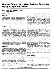
Fig. 1 Scheme of a DFIG equipped wind turbine.
v g, abc
2ème conférence Internationale des énergies renouvelables CIER-2014 Proceedings of Engineering and Technology - PET Copyright - IPCO 2015 II. MATHEMATICAL MODEL OF THE GENERATOR The Generator converts energy derived from the wind into electrical energy. The DFIG based a wound rotor and an AC/DC/AC based PWM converter (back-to-back converter with capacitor dc-link), the stator windings is directly connected to the grid while the rotor winding is interfaced through a power electronic converter (AC/DC/AC) [9]. The modeling of the DFIG is described in the d-q Park reference frame. The mathematical representation of the DFIG can be described by the equations below [2], [5] and [10]. The stator and rotor voltages: vds v qs vdr v qr
Accordingly, we align the d-axis along the stator flux vector position, as shown in Fig.2. ωs βr βs φs
Vs
d - axis
θs
θr q - axis
αr ωr Rotor-linked frame
θ αs Stator-linked frame
Fig.2 Orientation of the stator flux
d = R s ids + φds − ωs φqs dt d = R s iqs + φqs + ωs φds dt d = R r idr + φdr − ωr φqr dt d = R r iqr + φqr + ωr φdr dt
(1)
(2)
Which is the principle of the stator-flux-oriented vector control approach, this approach is regarded by the WECS as a natural application and the most commonly utilized frame for the design and analysis of control strategy for the DFIG [5], and it allows to the DFIG to regulate separately the stator active and reactive powers by means of rotor current regulation [5], [7], [15]. So, under this assumption we can write:
Where R s and R r are, respectively, the stator and rotor phase resistances. ω = p ⋅ Ωmec is the electrical speed and p is the pair pole number.
φds = L s ids + Mi dr (3) φqs = L s iqs + Mi qr φdr = L r idr + Mi ds (4) φqr = L r iqr + Mi qs Where ids , iqs , and i dr , iqr are, respectively, the direct and quadrate stator and rotor currents. The DFIG electromagnetic torque is given as: (5)
The stator active and reactive powers are defined as:
Ps = vds ⋅ ids + vqs ⋅ iqs Q s = vqs ⋅ ids − vds ⋅ iqs
(7)
Using the condition above, supposing that the grid system is steady, having a single voltage V s that leads to stator’s constant flux φs , we can easily deduce the voltages as:
The flux linkages equations can be expressed as:
T em = p (φds iqs − φqs ids )
φds = φs ⇒ φqs = 0
(6)
III. CONTROL STRATEGY OF THE DFIG
vds = 0 vqs = ωs ⋅ φs = V s
(8)
If per phase stator resistance is neglected, which is a realistic approximation for medium power machines used in WECS, the stator voltage vector is consequently in quadrate advance in comparison with the stator flux vector. Rotor voltages can be expressed by:
vdr = σLr v = σL r qr
didr M dφds + Rr idr − σLr ω r iqr + dt Ls dt diqr dt
+ Rr iqr + σLr ω r idr
M + s Vs Ls
(9)
Where V s is the stator voltage magnitude assumed to be constant and s is the slip range, we can rewrite the rotor voltages as follows:
A. Decoupled Control of the active and reactive powers
The function of the rotor circuit power electronic converter is to control the DFIG active and reactive powers [9], [7], since the DFIG is connected to the utility grid, the power produced by the (generator) must be controlled independently.
vdr = σLr v = σL r qr
didr + Rr idr + femd dt diqr + Rr iqr + femq dt
(10)
2ème conférence Internationale des énergies renouvelables CIER-2014 Proceedings of Engineering and Technology - PET Copyright - IPCO 2015
M Ps = Vs I qs = −Vs L I qr s Vsφs Vs M Qs = Vs I ds = I dr − Ls Ls
y*
(12)
Field oriented control of the DFIG can then be applied with the active and reactive power considered as variables to be controlled. And, we consequently the bloc diagram is presented in Fig. 3.
fem,d
vdr
+−
vqr
−Vs ⋅
+−
M 1 Ls (σLr ⋅ S + Rr )
−Vs ⋅
Ls −1
Vs ⋅ φs
+ +
Qs
e K e
+_
y d dt
K de
Ku
Rules Base
u
Fig. 5 Fuzzy logic structure.
Where the error e and its rate of change de are the input variables; K e , K de and K u are inputs and outputs scaling gains. For the proposed FLC, The inputs to the direct and quadrate axis rotor current fuzzy controllers are the d- and qaxis rotor current errors [5]: * ei (n) = idr (n) − idr (n) dr * eiqr (n) = iqr (n) − iqr (n)
Ps
M 1 Ls (σLr ⋅ S + Rr )
de
Inference System
Defuzzification
fem d = −σL r ωr iqr (11) M fem q = σL r ωr idr + s L V s s The active and reactive power can then be expressed only versus these rotor currents as:
2) Fuzzy Logic Controller (FLC) To regulate the DFIG wind turbine, Fuzzy Logic Control (FLC) is used because of the nonlinearity of the system. The basic formation of a FLC is consisted of four parts: Fuzzification block determining inputs membership values. The Fuzzy Inference System FIS evaluates at each time which control rules are appropriate, using the fuzzy knowledge based block. The deffuzification block calculates the crisp output of the rules leading to the optimal plant control. Fig. 5 shows the block diagram of the fuzzy control.
Fuzzification
With fem d and fem q are the crosses coupling terms between the d − axis and q − axis:
(17)
And their changes in error:
fem,q * ∆ei (n) = idr (n) − idr (n − 1) dr * ∆eiqr (n) = iqr (n) − iqr (n − 1)
Fig. 3 The coupled model of active and reactive stator powers.
B. Controllers synthesis
Respectively, the outputs of the two fuzzy controllers are idr and iqr . The input and output linguistic variables of the
1) PI controller synthesis This controller is simple to elaborate. Fig. 4 shows the block diagram of the system implemented with this controller. The terms K p and K i represent respectively the proportional
two fuzzy controllers have been quantized in the following five fuzzy subsets: TABLE I THE FUZZY CONTROL RULE BASES.
and integral gains. e
Ps * ,Qs * +
−
irq * , ird *
Re gPI
(18)
NL
NS
ZE
PS
PL
NL NL NL NS ZE
NL NS NS ZE PS
NL NS ZE PS PL
NS ZE PS PS PL
ZE PS PL PL PL
de
−V s
Ps ,Qs Fig. 4 Structure of PI controller
M Ls
Ps ,Qs
NL NS ZE PS PL
2ème conférence Internationale des énergies renouvelables CIER-2014 Proceedings of Engineering and Technology - PET Copyright - IPCO 2015 The fuzzy sets have been determined as: NL, Negative Large, NS, Negative Small and ZE, Zero, PS, Positive Small, PM positive medium, PL, Positive Large, respectively. The input/output variables used in this paper are fuzzified by seven symmetrical and triangular membership functions (MFs) (Fig. 6(a), (b) and (c)) normalized in the universe of discourse between -1 and +1. µe NL
NS ZE
µde PS
PL
NL 1.0
1.0
NS
ZE
PS
PL 1.0
1.0
e -1.00
0
-0.70 -0.35
0.35 0.70
de
1.00
-1.00
0
-0.70 -0.35
(a)
0.35 0.70
1.00
(b)
µdu NL
NS ZE
PS
PL 1.0
1.0
du -1.00
0
-0.70 -0.35
0.35 0.70
1.00
(c)
(d)
Fig. 6 The memberships of the: a – Error, b - Error variation, c - Command variation, d - Control surface.
The block-diagram of the variable structure control of the DFIG is presented on Fig.7. The stator active and reactive powers are controlled. ∗
Pm
v rd ∗
v rq
dq PWM
DFIG
abc
s
Ωr
RSC
C
Gearbox
M Vs Ls
∗
∗
∗
v rq
+ v rq ,1
iqr PI
+ +
-
f em ,q
+
∗
−
Ls MV s
−
Ls MV s
Ps
iqr
C1 M s Vs Ls
+ v rd ,1 + +
f em ,d
∗
∗
C2
idr PI
+ idr
+ -
∗
Qs
Grid
Vs 2 Lsω s
Fig. 7 Overall oriented field control of DFIG in WECS with different controllers.
IV. RESULTS AND DISCUSSION In this section, we present the simulations for a 7.5kW DFIG connected to a 220V/50Hz grid, under the MATLAB / Simulink environment. The machine's parameters are presented below: Three pole pairs, Rs = 0.455Ω, Ls = 0.084 H, M = 0.078 H, Rr = 0.62 Ω, Lr = 0.081 H The simulations are done in purpose to study the responses of wind turbine and its control with different controllers to analyze the influence of a speed variation of the DFIG on active and reactive powers. The active and reactive power references are maintained to 5 kW and −5 kVAR and at t = 0 .5 s the speed varies from 1350 rpm to 1450 rpm . At time= 1.5 s the speed varies also from 1450 rpm to 1300 rpm . A variable step solver is used with an automatic step size and with a relative tolerance of 1e-3. We notice that, those figures represent a good tracking and performances in terms of dynamics and responses. The classical PI controller is limited, which is only based on the machine’s parameters and their eventual variations are not taken into account. In fact, for this controller, a speed variation induces an important peak value of the active and reactive powers.Although theFuzzy Logic Controller satisfies the system dynamics, which presents no disturbances in during the variation of speed. The dynamics of FLC react quickly and without exceeding. Indeed, FLC doesn’t pose a problem for the machine exploitation. It can ensure the stability and the good quality of the generated power when the speed is varying.
V. CONCLUSION The doubly fed induction generator is receiving increasing attention for wind energy conversion system. In this paper, we have presented Wind Energy Conversion System based Double Fed Induction Generator. The control of the generator inverter has been presented in order to control the active and reactive powers exchanged between the generator and the grid. Field oriented control is applied, is based on the calculated rotor currents from the active and reactive powers and measuring the rotor currents. Two different controllers are synthesized and compared. Under the simulation results we conclude that the FLCis capable to reduce the over current in the rotor circuit during transient period, besides increasing the transient stability margin as well as improving the overall DFIG time domain performance.
2ème conférence Internationale des énergies renouvelables CIER-2014 Proceedings of Engineering and Technology - PET Copyright - IPCO 2015 REFERENCES [1]
[2]
[3]
[4]
[5]
[6]
[7]
[8]
[9]
A.Tapia, G.Tapia, J. XabierOstolaza, and J. Ramón Sáenz, "Modeling and Control of a Wind Turbine Driven oubly Fed Induction Generator ", IEEE Transaction on energy conversion, Vol. 18, No 2, June 2003, pp. 194-204. J. Liang, W. Qiao, and Ronald G. Harley, "Direct Transient Control of Wind Turbine Driven DFIG for Low Voltage Ride-Through", IEEE Proceeding, Lincoln, NE, June 24-26, 2009 pp. 1-7. A.A. El-Sattar, N.H. Saad, M.Z. Shams El-Dein, "Dynamic response of doubly fed induction generator variable speed wind turbine under fault", Elsevier Electric Power Systems Research, Vol. 78, No. 7, Jul. 2008, pp. 1240-1246. J. Zhao, X. Li, J. Hao, J. Lu, "Reactive power control of wind farm made up with doubly fed induction generators in distribution system", Elsevier Electric Power Systems Research, Vol. 80, No. 6, June 2010, pp. 698-706. R. Pena, J. C. Clare, and G. M. Asher, "Doubly fed induction generator using back-to-back PWM converter and is application to variable-speed wind–energy generation", Proc. IEE B Electr. Power Appl, Vol. 143, No. 3, May 1996, pp. 231–241. S. Muller, M. Deicke, and R. W. De Doncker, "Doubly fed induction generator systems for wind turbines ", IEEE Industry Applications Magazine, Vol. 8, No. 3, May/Jun 2002, pp. 26–33. R. Cárdenas, R. Pena, S. Alepuz, G. Asher, " Overview of Control Systems for the Operation of DFIGs in Wind Energy Applications ", IEEE Trans. Industrial Electronics, Vol. 60, No. 7, July 2013. M. Moghbel, H. TariMokui , M. A.S. Masoum, M. Mohseni, "Reactive Power Control of DFIG Wind Power System Connected to IEEE 14 Bus Distribution Network ", 22nd Australasian Conference , Bali September 26-29, 2012, pp. 1–7. M. Ghofrani, and A. Arabali, , M. Etezadi-Amoli, "Modeling and Simulation of a DFIG-Based Wind-Power System for Stability
PI
[12] [13]
[14]
[15]
[16]
[17]
.
PI
FLC
4
3
Current Idr (A)
1 0
0 -1 0.5
1
1.5
0 -50
0.5
1
1.5
2
-100
0
0.5
1
1.5
2
0
0.5
1
1.5
2
0
0.5
1
1.5
2
4
4
x 10
x 10 3
3
2
2
1
1
0
0 0.5
1
Time (s)
1.5
2
50
50
0
0
-50
-50
-100
-100
-1
-1 0
0
-50
0
2
50
50
2
2
-2 0
FLC
x 10
Current Iqr (A)
Active power P(W)
[11]
4
4
x 10
Reactive power Q(VAR)
[10]
Analysis", Power and Energy Society General Meeting; San Diego, CA, July 22-26, 2012, pp. 1-8. B.Singh, S. Kumar Aggarwal, and T. Chandra Kandpal, "Performance of Wind Energy Conversion System using a Doubly Fed Induction Generator for Maximum Power Point tacking", Industry Applications Society Annual Meeting (IAS), Houston, Oct 3-7, 2010, pp. 1-7. L. M Fernandez, C.A. Garcia, F. Jurado, "Comparative study on the performance of control systems for doubly fed induction generator (DFIG) wind turbines operating with power regulation", Energy, Vol. 33, 2008, pp. 1438-1452. P.C Krause, O.Wasynczuk and S. D.Sudhoff, Analysis of electrical machinery and drive system ,IEEE .Press :2002. A. Boyette, S.Saadate, P. Poure, " Direct and indirect control of a Doubly Fed Induction Generator wind turbine including a storage unit", 32nd Annual Conference On IEEE Industrial Electronics; Paris , Nov 06-10,2006, pp. 2517-2522. A. Dekhane, S. Lekhchine, T. Bahi, S. Ghoudelbourg, H. Merabet, " DFIG Modeling and Control in a Wind Energy Conversion System", 1st International Conference on Renewable Energies and Vehicular Technology, Hammamet, March 26-28, 2012, pp. 287-292. K.Belmokhtar, M.L Doumbia and K. Agbossou, " Modelling and Fuzzy Logic Control of DFIG Based Wind Energy Conversion Systems", IEEE International Symposium on Industrial Electronics, Hangzhou, May 28-31, 2012, pp. 1888-1893. Munteanu, Bacha S, Bratcu A, Guiraud J, Roye D. "Energy reliability optimization of wind energy conversion systems by sliding mode control", IEEE Trans Energy Convers, 2008, pp. 975–85. J. Hu, H. Nian, B. Hu, Y. He, and Z. Zhu, "Direct active and reactive power regulation of DFIG using sliding-mode control approach", IEEE Trans. Energy Convers, vol. 25, Dec. 2010, pp.1028-1039.
0
0.5
1
Time (s)
Rotor active and reactive powers
1.5
2
0
0.5
1
1.5
2
Time (s)
Time (s)
Direct and quadrate rotor currents
Fig. 8 Effect of a speed variation (indirect control) equipped with PI and FLC controllers