A Robust Frequency Estimation Technique Based on Three Consecutive Samples for Single-Phase Systems *Md. Shamim Reza, Student Member, IEEE, Mihai Ciobotaru, Member, IEEE, and Vassilios G. Agelidis, Senior Member, IEEE E-mail: *
[email protected],
[email protected],
[email protected] Australian Energy Research Institute and School of Electrical Engineering and Telecommunications The University of New South Wales, Kensington, Sydney, NSW 2052, Australia
Abstract - This paper proposes a robust technique for fundamental frequency estimation of a single-phase grid voltage waveform under distorted conditions. The technique consists of an improved algorithm based on three consecutive samples (3CS) and a finite-impulse-response (FIR) filter. The technique can reject the negative effects caused by direct current (DC) offset, harmonics, notches and spikes. It can also estimate the fundamental frequency for a wide range of variation, thus complying with the standard. When compared with a conventional technique based on 3CS and a FIR filter, the proposed technique does not require setting a threshold value of the middle sample of 3CS for removing the ill-condition. Moreover, it is less affected by the DC offset, voltage sag, voltage flicker, notches and spikes as compared to the conventional technique. Simulation and real-time experimental results are presented to verify the robustness of the proposed technique.
Index Terms - Finite-impulse-response filter, Fundamental frequency, modulating function, robust estimation, three consecutive samples, and single-phase voltage system.
Declaration – This work is an extension of the paper [45] that has already been presented at an IEEE conference. Title of [45]: Real-time estimation of single-phase grid voltage frequency using a modulating function based technique Presented at the IEEE Conference ECCE Asia Down Under, June 03-06, 2013, Melbourne, Australia. This manuscript is not submitted to any other journal and is not currently considered for publication by any other journal.
* Corresponding author
1 / 21
I. INTRODUCTION The use of the distributed generation (DG) systems is increasing due to the problems of the global warming and the exhaustion of the fossil fuels [1]. The DG systems are connected with the distribution electrical grid using power electronic converters. The interface system of the grid-connected power converters requires proper synchronization with the grid voltage at the point of common coupling (PCC) [1]. The digital signal processing (DSP) technique used for synchronization of the gridconnected power converters has to be fast, accurate and high degree of immune and non-sensitive to the grid disturbances such as direct current (DC) offset, harmonics, frequency drifts, voltage sag, voltage flicker, phase jump, notches and spikes [2-4]. The phase-locked loop (PLL) is a commonly used DSP technique for grid synchronization applications [5-10]. However, the performance of the PLL is affected by the DC offset and harmonics [3, 4, 11-14]. In-loop filter can also be used to improve the performance of the PLL at a cost of reduced bandwidth, thus leading to a slower dynamic response [12-14]. A cascaded delayed signal cancellation (CDSC) strategy can also be used as a pre-filter of the PLL to reject the negative effects caused by the DC offset and harmonics [15-18]. The CDSC strategy requires the frequency information obtained by the PLL and hence introduces an additional interdependent loop. The single-phase PLL systems also require quadrature voltage waveforms and there is less information in single-phase systems than in three phase ones [10]. Another drawback of the PLL is that the phase and frequency are estimated within a single loop which causes large frequency transient during phase jumps under grid faults [19]. The effect of this undesired frequency swing are also reflected back on the phase estimation and hence causes delay in the process of synchronization [19]. The frequency swing can be reduced by means of a frequency-locked loop (FLL) and a quadrature signal generator based on a second-order generalized integrator (QSG-SOGI) [20, 21]. The QSG-SOGI has filtering capability to reject harmonics but the presence of DC offset and lower order harmonics can introduce distortions [3, 11, 22]. A parallel network consisting of a FLL and multiple QSG-SOGIs can be used to reject the negative effects caused by harmonics [23]. A separate frequency estimation technique can also be used for the QSG-SOGI or CDSC systems, which helps to remove an interdependent loop and hence eases the tuning process and makes the synchronization technique more robust [15-18, 24-26]. The frequency information is also required for the purposes of control and protection of the DG systems [27, 28]. The IEC standard 61727 defines that a photovoltaic system has to be disconnected from the grid when the grid frequency exceeds ±1 Hz of the rated frequency [29, 30]. On the other hand, according to the IEEE standard 1547, the frequency of a microgrid cannot differ from the grid frequency more than 0.1% during the reconnection with the grid [30, 31]. There are many DSP techniques reported in the technical literature for the estimation of grid voltage fundamental frequency [24, 30, 32-43]. Among these techniques, the zero crossing detection (ZCD) one is relatively simple and widely used but provides estimation after every half fundamental cycle [32]. The ZCD technique may also provide erroneous results due to the
2 / 21
multiple zero crossings introduced by noise [32, 33]. A pre-filter or a curve fitting algorithm can be integrated with the ZCD technique to reduce the negative effects caused by noise [32-34]. The spectral leakage property of the discrete Fourier transform (DFT) can be used to obtain the fundamental frequency [35, 36]. A large size moving window is required to avoid the interference caused by lower order harmonics. In addition, the use of three DFT filters may increase the real-time computational burden of the technique [35, 36]. The recursive DFT can be used as a demodulation method for frequency estimation [37-39]. However, the recursive DFT is subjected to instability due to the accumulation error when implemented on a digital signal processor [44]. On the other hand, a high-order finite-impulse-response (FIR) differentiation filter including a conventional demodulation method can be used to provide the frequency estimation at a cost of slower dynamic response [40]. A modulating function (MF) strategy can also be applied to track the fundamental frequency [24]. However, the MF based frequency tracking technique requires two high-order FIR filters which may increase the computational efforts for real-time implementations. A relatively simple technique based on three consecutive samples (3CS) of a filtered grid voltage can also be used for fundamental frequency estimation [30, 41-43]. However, the 3CS based technique is ill-conditioned when the instantaneous value of the middle sample is equal or close to zero. The ill-condition can also be removed by holding the previously estimated frequency when the middle sample is close to zero [30]. Nevertheless, the methodology for obtaining the threshold value of the middle sample for removing the ill-condition is not reported in [30]. The performance of the technique is also affected when the DC offset and harmonics are not properly rejected by filtering [30, 41-43]. In addition, the 3CS based technique is sensitive to the voltage transients. The objective of this paper is to propose a robust technique for the estimation of single-phase grid voltage fundamental frequency under distorted conditions. The technique is based on the 3CS and a FIR filter. It does not require setting a threshold value of the middle sample for removing the ill-condition and can also reject the negative effects caused by the DC offset, harmonics, notches and spikes. The proposed 3CS based technique and its preliminary results were first introduced in [45]. The results presented in [45] were limited without covering the cases of different operating conditions. Based on the standard requirements for estimation accuracy under a wide range of frequency variation with harmonics [46, 47], simulation performance of the proposed technique is reported in this paper. The experimental performance of the technique is also documented under different conditions such as DC offset, harmonics, frequency step, frequency sweep, voltage sag, voltage flicker, phase jump, notches and spikes. In addition, the experimental performance of the technique is compared with a similar conventional technique based on the 3CS and a FIR filter [30]. The rest of the paper is organized as follows. The proposed 3CS based technique is described in section II. Simulation results of the proposed and conventional 3CS based techniques are presented in section III. Section IV contains the experimental performance comparison of the proposed and conventional techniques. Finally, the conclusions are summarized in section V. 3 / 21
II. PROPOSED FREQUENCY ESTIMATION TECHNIQUE The single-phase grid voltage fundamental component including the DC offset at the n sampling instant can be expressed by v n v0 v1 n
(1)
where v0 is the DC offset, v1 is the fundamental component and can be expressed by v1 n A1 n sin 2 f n nTs 1
where A1, f, θ1, Ts and fs=1/Ts are the fundamental voltage amplitude, fundamental frequency, initial phase angle, sampling period and sampling frequency, respectively. A. 3CS Based Frequency Estimation Technique The following relation can be obtained from (1) when the DC offset is zero (v0=0) and the parameters are constant within the 3CS of the fundamental voltage component [30, 41-43]. v n v n 2 2v n 1 cos 2 fTs p n q(n)r
(2)
where p n v n v n 2 q n 2v n 1 r cos 2 fTs
The above relation based on the 3CS of the grid voltage fundamental component can be used to estimate the value of r and f. However, the relation (2) is not true when the grid voltage fundamental component contains nonzero DC offset (i.e. v0≠0). Nevertheless, the following relation is always true whether the grid voltage fundamental component contains zero or nonzero DC offset. p n q (n)r 1
1
where p n v n v n 2 1
1
1
q n 2v n 1 1
1
4 / 21
(3)
and the superscript “1” indicates first-order derivative with respect to time. Equation (3) can be used to estimate the value of r and f from the grid voltage fundamental component with/without DC offset. However, the estimation of f using (3) is sensitive to the change of the fundamental parameters within the 3CS of the grid voltage. Equation (3) is also ill-conditioned when v(1)(n1)=0. Moreover, the estimation of frequency using (3) is not suitable for the grid voltage containing disturbances such as harmonics and noise. Additionally, the differentiation operation increases the negative effects caused by the presence of the high frequency disturbances. The above shortcomings of the 3CS based fundamental frequency estimation technique can be rejected by using an integration based MF strategy [24, 48]. B. Proposed 3CS Based Frequency Estimation Technique The MF can be denoted by φ(t), where t indicates time in continuous domain. The MF can be differentiated K times {φK(t)}. The ith derivative of the MF over a finite time interval [0, Tw] satisfies the following condition [24, 48] K(i ) 0 K(i ) Tw 0
(4)
where i=0,1,2,…,K-1 and Tw is the size of the window. The continuous time grid voltage, as denoted by v(t), can be modulated by taking the inner product with the MF. The modulated grid voltage over the time window (Tw) can be expressed by [24, 48]
v, K v t K t dt Tw
0
(5)
The above modulation relation also holds for the ith derivative of the grid voltage {v(i)(t)} and can be expressed by [24, 48] v , K v t K t dt Tw
i
i
0
(6)
The integration based MF strategy, as given by (6), can reject the negative effects caused by the high frequency disturbances present in the grid voltage. The high frequency disturbance rejection capability of the MF strategy is also improved as the window size (Tw) of the integration is increased. After the modulation, the boundary conditions of the grid voltage are set by the terminal conditions of the MF, which make it possible to transfer the differentiation operation from the grid voltage on to the MF [24, 48]. Therefore, the interchange of the differentiation operation between the grid voltage and the MF can be expressed by v , K 1 v, K i
i
i
(7)
The interchange of the differentiation operation from the grid voltage on to the MF, as given by (7), helps to eliminate the requirement of differentiating the grid voltage distorted by high frequency disturbances.
5 / 21
In continuous time domain, equation (3) can be written as p t rq (t ) 1
1
(8)
Therefore, based on (6), equation (8) can be modulated and is expressed by
Tw
0
p t K t dt r q t K t dt Tw
1
1
0
(9)
Based on (7), equation (9) can also be expressed by
Tw
0
p t K(1) t dt r q t K(1) t dt Tw
0
(10)
For implementing in a digital signal processor, the continuous time domain integration based MF strategy, as given by (10), can be expressed in discrete domain. Therefore, the simplified discrete form of (10) can be written as m 1
m 1
p n l l r q n l l 1 K
l 0
1 K
l 0
P n rQ n
(11)
where
P n
m 1
p n l l l 0
m 1
1 K
Q n q n l K l 1
l 0
and m=Tw/Ts is the number of samples in the integration window of time duration Tw. It can be seen from (11) that a first-order derivative (i=1) of the MF is required and hence the value of K has to satisfy the condition K≥2. The value of r and f can be obtained from (11), which can reject the negative effects caused by the DC offset and harmonics. However, equation (11) is ill-conditioned to estimate the frequency, when the value of Q(n) is zero. To avoid this shortcoming of (11), a recursive algorithm can be used and is presented below [24]. The value of r at the n sampling instant (rn) can be obtained by minimizing an index function Jn given by
Jn
2 1 n nh P h rn Q h 2 h 0
6 / 21
(12)
where ρ is a constant parameter in the interval [0,1]. The parameter ρ represents a forgetting factor to exponentially discard the old data in the recursive scheme, which means that the most recent measurements have a higher weight as compared to that of the old measurements. A low value of ρ improves the dynamic capability of the technique to track the time-varying fundamental frequency and vice versa [24]. On the other hand, a high value of ρ increases the disturbance rejection capability of the technique. Therefore, a compromise between good dynamics and accuracy is required when choosing the value of ρ. The value of rn which minimizes Jn can be obtained from the following condition.
d Jn 0 drn
(13)
Therefore, the differentiation of the index function Jn with respect to rn can be expressed by n d J n n h P h rn Q h Q h drn h 0
(14)
Based on the condition (13), the value of rn can be obtained from (14) and is given by n
rn
h 0 n
nh
P h Q h
n h Q h
(15) 2
h0
Equation (15) can also be represented as a recursive form and is given by
rn
n 1 rn 1 P n Q n n
(16)
where
n n h Q h n 1 Q n n
2
2
h 0
Therefore, the grid voltage fundamental frequency at the n sampling instant can be estimated by
cos 1 (rn ) fˆ n 2 Ts
(17)
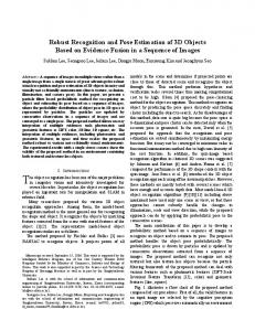
where the hat sign indicates the estimated quantity. Equation (17) can be used to estimate the time-varying fundamental frequency from a non-periodic single-phase grid voltage distorted by DC offset and harmonics. The implementation of (17) is shown in Fig. 1. As it can be noticed, P(n) and Q(n) are the outputs of two discrete-time FIR filters, where the inputs of the
7 / 21
filters are p(n) and q(n), respectively. The coefficients of the FIR filters are the same and determined by the MF K1 l , where l=0,1,2,…,m-1 and K≥2. As the coefficients of the FIR filters are the same, and p(n) and q(n) are also linearly related with the grid voltage samples v(n), hence only one FIR filter can be used to filter v(n) instead of filtering p(n) and q(n) separately. Therefore, the simplified form of the proposed 3CS based frequency estimation technique is presented in Fig. 2.
rn 1 v n
z 1
z 1
2
p n
q n
K(1) 0 K(1) 1 z 1 K(1) 2 z 2
K(1) 0 K(1) 1 z 1 K(1) 2 z 2
P n
K(1) m 1 z ( m1)
K(1) m 1 z ( m1)
Q n
. 2
z 1
rn
n
cos 1 .
1 2 Ts
fˆ n
z 1 n 1
FIR filters based on the spline type modulating function
Fig. 1. Proposed 3CS based technique for the estimation of single-phase grid voltage fundamental frequency. rn 1 v n
K(1) 0 K(1) 1 z 1 K(1) 2 z 2
K(1) m 1 z ( m1)
z 1
z 1
FIR filter based on the spline type modulating function 2
P n Q n
. 2
z 1
n
rn
cos 1 .
1 2 Ts
fˆ n
z 1 n 1
Fig. 2. Simplified form of the proposed 3CS based technique, as shown in Fig. 1, for the estimation of single-phase grid voltage fundamental frequency.
The coefficients of the FIR filter are obtained from a spline type MF. The ith derivative of the spline function with maximum derivative order K and characteristics time Tc=Tw/K can be expressed by [24]
Ki
K j K 1 g ji lTs jTc for i =0,1,...,K -1 j 0 j l K j K 1 lTs jTc for i =K j j 0
where 1 K i 1 for lTs ε jTc , Tw K i 1 ! lTs jTc g ji lTs jTc 0 otherwise
and δ(lTs) is the Dirac delta function.
8 / 21
(18)
C. Standard Requirements for Frequency Variation Several standards are reported in the technical literature which defines the deviation range of the grid voltage fundamental frequency. The European standard EN-50160 defines that under normal operating conditions the fundamental frequency shall be within a range of 50 Hz -6/+4 % (47 Hz to 52 Hz) during 100 % of the time, for systems with synchronous connection to an interconnected system [49]. The IEEE standard C37.118.1 specifies the frequency ranges of 50 Hz ± 2 Hz (48 Hz to 52 Hz) and 50 Hz ± 5 Hz (45 Hz to 55 Hz) for P and M class phasor measurement units (PMUs), respectively [39, 50]. On the other hand, the IEC standard 61000-4-30 defines that the testing fundamental frequency can be varied from 42.5 Hz to 57.5 Hz for the 50 Hz system [46]. The IEC standard 61000-4-7 [47] considers 10 fundamental cycles (0.2s) to complete the phasor estimation tasks for the 50 Hz system. Moreover, the IEC standard 61000-4-7 defines that the maximum acceptable relative error of the fundamental frequency estimation is 0.03%. The percentage of the relative error can be defined by
Relative Error (%) =
where the symbol
Actual Value - Estimated Value Actual Value
×100%
(19)
indicates absolute value. The fundamental frequency variation range of 42.5 Hz to 57.5 Hz is considered
in this paper for evaluating the performance of the proposed 3CS based frequency estimation technique.
III. SIMULATION RESULTS The simulation performance of the proposed 3CS based technique in MATLAB/Simulink is documented in this section. The parameters of the technique are given in Table I. The estimation of ±7.5 Hz fundamental frequency steps using the proposed technique is shown in Fig. 3, where the grid voltage contains 1.0 p.u. fundamental voltage amplitude and 10.67% total harmonic distortion (THD), as given in Table II. Harmonics given in Table II are chosen in accordance with the standard EN-50160 [30, 49]. As it can be noticed in Fig. 3, the proposed technique takes around 2 fundamental cycles as settling time for tracking of ±7.5 Hz frequency steps.
TABLE I PARAMETERS OF THE PROPOSED 3CS BASED TECHNIQUE Tw=40 ms
fs=5.0 kHz
m=200
9 / 21
K=6
ρ=0.96
(a) Fundamental Frequency (Hz)
49 48 47 46 45 44 43 42 1.98 58
(b) Fundamental Frequency (Hz)
Proposed 3CS Actual
50
2
2.02
2.04
2.06
2.08
2.1
57 56
Proposed 3CS Actual
55 54 53 52 51 50 1.98
2
2.02
2.04
2.06
2.08
2.1
Time (s)
Fig. 3. Simulated frequency steps estimation under harmonics, as given in Table II, using the proposed 3CS based technique. (a) -7.5 Hz (50 Hz to 42.5 Hz). (b) +7.5 Hz (50 Hz to 57.5 Hz).
TABLE II HARMONIC AS A PERCENTAGE OF FUNDAMENTAL COMPONENT IN ACCORDANCE WITH THE EUROPEAN STANDARD EN-50160 Harmonics
THD
3rd
5th
7th
9th
11th
13th
15th
17th
5.0%
6.0%
5.0%
1.5%
3.5%
3.0%
0.5%
2.0%
10.67%
The settling time taken by the proposed technique for different frequency steps estimation at 0° phase angle with 1.0 p.u. amplitude of the voltage waveform is shown in Fig. 4. As it can be seen, the proposed technique takes around two fundamental cycles as settling time for tracking the different frequency steps. On the other hand, the performance of the proposed technique for tracking +1 Hz frequency step at different amplitude levels and phase angles are shown in Fig. 5. In this case is noted that the settling time does not depend on the amplitude level (0.5 to 1.5 p.u.) for a particular phase angle of the voltage waveform. However, it varies slightly for different phase angles, as can also be seen in Fig. 5. The performance of the proposed technique for estimating frequency ramp with different slopes is shown in Fig. 6. In this case, the frequency estimation error increases almost linearly with the increasing of the frequency slope. However, the time delay to estimate the different frequency ramp is nearly constant and less than 1.5 fundamental cycles, as can also be noticed in Fig. 6.
10 / 21
Settling Time (ms)
50 45 40 35 30
-5
-4
-3
-2
-1
0
1
2
3
4
5
Frequency Step (Hz)
Fig. 4. Simulated settling time taken by the proposed 3CS based technique for different frequency steps estimation at 0° phase angle and 1.0 p.u. amplitude of the voltage waveform.
Settling Time (ms)
50 45 40 Phase angle=00 Phase angle=+300 Phase angle=+600 Phase angle=+900 Phase angle=+1200
35 30
0.5
0.6
0.7
0.8
0.9
1
1.1
1.2
1.3
1.4
1.5
Amplitude (p.u.)
Fig. 5. Simulated settling time taken by the proposed 3CS based technique for +1 Hz frequency step estimation at different amplitude levels and phase angles of the voltage waveform.
Error
30
Delay
2
20
1
10
0 0
20
40
60
80
Time Delay (ms)
Frequency Error (Hz)
3
0 100
Frequency Ramp (Hz/s)
Fig. 6. Simulated frequency estimation error and time delay obtained by the proposed 3CS based technique for frequency ramp with different slopes.
The steady-state performance of the proposed technique is shown in Fig. 7, where the grid voltage contains 1.0 p.u. fundamental voltage amplitude, 10.67% THD, as given in Table II, and the fundamental frequency is varied from 42.5 Hz to 57.5 Hz. As it can be noticed, the estimation error increases when the negative deviation of fundamental frequency increases from its nominal value. However, the estimated error decreases as the positive deviation of fundamental frequency increases from its nominal value. It can also be noticed from Fig. 7 that the relative error of the estimated fundamental frequency range of 42.5 Hz to 57.5 Hz under 10.67% THD remains inside the acceptable range (less than 0.03%) specified by the IEC standard 61000-4-7. 11 / 21
Frequency Error (Hz)
0.03
Error (Hz) Relative Error (%)
0.02
0.005
0.01
(%)
0.01
0 42
44
46
48
50
52
54
Relative Frequency Error
0.015
0 58
56
Fundamental Frequency (Hz)
Fig. 7. Simulated frequency estimation error at steady-state under harmonics, as given in Table II, using the proposed 3CS based technique.
Fig. 8 shows +7.5 Hz frequency step estimation under harmonics, as given in Table II, using the conventional 3CS based technique, where a high-order FIR filter is designed at fs=5 kHz and the parameters are given in Table I of [30]. A threshold value of ±0.005 p.u. for the middle sample is considered for removing the ill-condition of the conventional 3CS based technique. As it can be seen from Fig. 8, the technique presents unwanted oscillations during frequency step. However, a low-pass filter (LPF) can be used to reduce these oscillations, as can be noticed in Fig. 8, where the LPF-1 is an infinite-impulse response (IIR) filter of second-order and cut-off frequency of 100 Hz. A more accurate frequency estimation can be obtained by reducing the cut-off frequency of the LPF at the expense of slower dynamic response, as it can also be seen in Fig. 8, where the cut-off frequency of the second-order IIR LPF-2 is 40 Hz. The conventional technique with LPF-2 takes around 2 fundamental cycles as settling time during frequency step and is used in the next section for experimental performance comparison with the proposed technique under similar frequency dynamic condition.
Fundamental Frequency (Hz)
62 60 58 56
57.52
54
57.5
52
57.48 2.08
50 48 46 44 1.98
2.09
2.1
Conventional 3CS w/o LPF Conventional 3CS w/ LPF-1 Conventional 3CS w/ LPF-2 Actual 2
2.02
2.04
2.06
2.08
2.1
Time (s)
Fig. 8. Simulated frequency step (+7.5 Hz: 50 Hz to 57.5 Hz) estimation under harmonics, as given in Table II, using the conventional 3CS based technique.
12 / 21
IV. REAL-TIME EXPERIMENTAL RESULTS In this section, the performance of the proposed 3CS based technique is compared with the conventional 3CS based technique [30] on a real-time experimental setup. The laboratory setup for real-time experiments, as shown in Fig. 9, consists of hardware and software parts. The hardware part contains a programmable AC power supply, a voltage sensor, a dSPACE1103 (DS1103) control board and a personal computer (PC). The programmable AC power supply is used to generate the grid voltage (vLN, where the subscript LN indicates line-to-neutral) under different grid conditions. The voltage sensor measures the generated grid voltage and sends it to the 16 bit analog-to-digital converter of the DS1103 control board. On the other hand, the software part of the experimental setup consists of MATLAB/Simulink, DS1103 Real-Time Interface (RTI) and Control Desk Interface. The MATLAB/Simulink models of the proposed and conventional 3CS based techniques are compiled and uploaded to the DS1103 control board using the automatic code generation. The Control Desk Interface running on the PC is used to set the parameters in real-time and also to monitor the estimated values.
~
vLN
∕∕∕
Electrical Grid
Programmable AC Power Supply
Voltage Sensor
dSPACE 1103
Personal Computer
Fig. 9. Laboratory setup for real-time experiments.
The performance of the proposed and conventional 3CS based techniques is compared under following case studies: i. Steady-state with DC offset and harmonics (Case-1) ii. Frequency step and harmonics (Case-2) iii. Frequency sweep and harmonics (Case-3) iv. Voltage sag and harmonics (Case-4) v. Voltage flicker and harmonics (Case-5) vi. Phase jump and harmonics (case-6) vii. Notches, spikes and harmonics (case-7) In all the above case studies, the grid voltage fundamental component contains 10.67% THD, as given in Table II. The experimental results of the above case studies are captured from a digital oscilloscope. Case-1: Steady-State with DC Offset and Harmonics The grid voltage waveform, as shown in Channel 1 of Fig. 10, contains 5% DC offset and 10.67% THD. The harmonic contents are given in Table II. The fundamental frequency estimation using the proposed and conventional 3CS based 13 / 21
techniques is shown in Channel 2 and Channel 3, respectively. As it can be seen from Fig. 10, the conventional technique generates low frequency ripple in the frequency estimation and is also more affected by the DC offset when compared with the proposed one.
50 Hz
Channel 1: Grid Voltage Waveform Channel 2: Proposed 3CS (0.004 Hz/V) Channel 3: Conventional 3CS (0.004 Hz/V) /div /div
/div
/div
Fig. 10. Experimental case-1: steady-state with DC offset (5%) and harmonics.
Case-2: Frequency Step and Harmonics In this case, the performance of the proposed and conventional 3CS based techniques is documented for a fundamental frequency step including 10.67% THD, as given in Table II. A +7.5 Hz fundamental frequency step is considered in the harmonically distorted grid voltage waveform. The estimation of the fundamental frequency step using the proposed and conventional techniques is depicted in Fig. 11. Channel 2 and Channel 3 contain frequency estimation using the proposed and conventional techniques, respectively. As it can be seen from Fig. 11, both techniques provide similar frequency dynamics and their settling time is around 2 fundamental cycles. However, the proposed technique presents higher oscillations during the frequency transient as compared to the conventional one. It can be noticed from Fig. 8 that the conventional 3CS based technique also presents large oscillations due to a low and erroneous value of middle sample during the frequency step, and an additional LPF is used to reduce these oscillations whereas the proposed technique does not require such LPF.
Channel 2: Proposed 3CS (0.625 Hz/V) Channel 3: Conventional 3CS (0.625 Hz/V)
7.5 Hz
50 Hz /div
/div
/div
Fig. 11. Experimental case-2: frequency step (+7.5 Hz: 50 Hz to 57.5 Hz) and harmonics.
14 / 21
Case-3: Frequency Sweep and Harmonics A -10 Hz/s fundamental frequency sweep down to 42.5 Hz is considered in the grid voltage waveform distorted by harmonics, as given in Table II. The estimated fundamental frequency sweep using the proposed and conventional 3CS based techniques is shown in Channel 2 and Channel 3, respectively, of Fig. 12. As it can be seen, similar to the frequency step, both proposed and conventional techniques provide comparable dynamics for tracking the frequency sweep.
50 Hz
7.5 Hz
Channel 2: Proposed 3CS (0.625 Hz/V) Channel 3: Conventional 3CS (0.625 Hz/V) (Estimations are overlapped) /div
/div
/div
Fig. 12. Experimental case-3: frequency sweep (-10 Hz/s: 50 Hz to 42.5 Hz) and harmonics.
Case-4: Voltage Sag and Harmonics The performance of the proposed and conventional 3CS based techniques under 50% voltage sag and 10.67% THD, as given in Table II, is presented in Fig. 13, where Channel 1 contains grid voltage waveform, and Channel 2 and Channel 3 contain fundamental frequency estimation using the proposed and conventional techniques, respectively. As it can be seen, the conventional technique is more sensitive to the voltage sag and presents large oscillations in the estimation of fundamental frequency as compared to the proposed one.
50 Hz
Channel 1: Grid Voltage Waveform Channel 2: Proposed 3CS (1.25 Hz/V) Channel 3: Conventional 3CS (1.25 Hz/V)
/div /div
/div
/div
Fig. 13. Experimental case-4: voltage sag (50%) and harmonics.
15 / 21
Case-5: Voltage Flicker and Harmonics The performance of the proposed and conventional 3CS based techniques under voltage flicker and harmonics, as given in Table II, is shown in Channel 2 and Channel 3, respectively, of Fig. 14. The corresponding grid voltage waveform is shown in Channel 1 of Fig. 14 and contains 2.5 Hz, ±0.05 p.u. triangular voltage flicker and 10.67% THD. As it can be observed, the proposed technique is less sensitive to the presence of voltage flicker as compared to the conventional one.
50 Hz
Channel 1: Grid Voltage Waveform Channel 2: Proposed 3CS (0.02 Hz/V) Channel 3: Conventional 3CS (0.02 Hz/V) /div /div
/div
/div
Fig. 14. Experimental case-5: voltage flicker (±5%) and harmonics.
Case-6: Phase Jump and Harmonics The grid voltage waveform, as shown in Channel 1 of Fig. 15, contains a -30° phase jump and 10.67% THD. In this case, the estimation of the fundamental frequency using both proposed and conventional 3CS based techniques is also shown in Channel 2 and Channel 3, respectively. As it can be observed from Fig. 15, both proposed and conventional techniques are similarly affected by the phase jump and present undershoot in the estimation of frequency.
50 Hz
Channel 1: Grid Voltage Waveform Channel 2: Proposed 3CS (1.25 Hz/V) Channel 3: Conventional 3CS (1.25 Hz/V)
/div /div
/div
/div
Fig. 15. Experimental case-6: phase jump (-30°) and harmonics.
16 / 21
Case-7: Notches, Spikes and Harmonics In this case, the grid voltage waveform contains notches, spikes and harmonics, as given in Table II, and is shown in Channel 1 of Fig. 16. The performance of the proposed and conventional 3CS based techniques is also shown in Channel 2 and Channel 3, respectively, of Fig. 16. As it can be observed, the performance of the proposed technique is not affected by the notches and spikes. On the other hand, the conventional technique provides an offset error in the estimation of fundamental frequency due to the presence of notches and spikes.
50 Hz
Channel 1: Grid Voltage Waveform Channel 2: Proposed 3CS (0.01 Hz/V) Channel 3: Conventional 3CS (0.01 Hz/V) /div /div
/div
/div
Fig. 16. Experimental case-7: notches, spikes and harmonics.
V. CONCLUSIONS A robust technique for the estimation of single-phase grid voltage fundamental frequency has been proposed in this paper. The technique relies on an improved algorithm based on three consecutive samples and a finite-impulse-response filter. It can reject the negative effects caused by the presence of the DC offset, harmonics, notches and spikes, and can also provide the estimation of a wide range of fundamental frequency variation under harmonics with an acceptable error specified by the standard. The technique does not need to set a threshold value of the middle sample of three consecutive samples for removing the ill-condition when compared with a conventional technique based on three consecutive samples and a finite-impulseresponse filter. In addition, based on similar frequency dynamics, the proposed technique is less affected by the DC offset, voltage sag, voltage flicker, notches and spikes as compared to the conventional technique. Moreover, unlike the conventional one, the proposed technique does not require additional low-pass filter. The presented experimental results have confirmed the effective real-time application of the proposed fundamental frequency estimation technique.
17 / 21
REFERENCES [1]
F. Blaabjerg, R. Teodorescu, M. Liserre, and A. V. Timbus, "Overview of control and grid synchronization for distributed power generation systems," IEEE Trans. Ind. Elect., vol. 53, no. 5, pp. 1398-1409, Oct. 2006.
[2]
L. Asiminoaei, F. Blaabjerg, and S. Hansen, "Detection is key - Harmonic detection methods for active power filter applications," IEEE Ind. App. Mag., vol. 13, no. 2, pp. 22-33, July/Aug. 2007.
[3]
M. Karimi-Ghartemani, S. A. Khajehoddin, P. K. Jain, A. Bakhshai, and M. Mojiri, "Addressing DC component in PLL and notch filter algorithms," IEEE Trans. Power Elect., vol. 27, no. 1, pp. 78-86, Jan. 2012.
[4]
S.-H. Hwang, L. Liu, H. Li, and J.-M. Kim, "DC offset error compensation for synchronous reference frame PLL in singlephase grid-connected converters," IEEE Trans. Power Elect., vol. 27, no. 8, pp. 3467-3471, 2012.
[5]
P. Rodriguez, J. Pou, J. Bergas, J. I. Candela, R. P. Burgos, and D. Boroyevich, "Decoupled double synchronous reference frame PLL for power converters control," IEEE Trans. Power Elect., vol. 22, no. 2, pp. 584-592, Mar. 2007.
[6]
S. Golestan, M. Monfared, F. D. Freijedo, and J. M. Guerrero, "Design and tuning of a modified power-based PLL for single-phase grid-connected power conditioning systems," IEEE Trans. Power Elect., vol. 27, no. 8, pp. 3639-3650, Aug. 2012.
[7]
M. Karimi-Ghartemani, M. Mojiri, A. Safaee, J. A. Walseth, S. A. Khajehoddin, P. Jain, and A. Bakhshai, "A new phaselocked loop system for three-phase applications," IEEE Trans. Power Elect., vol. 28, no. 3, pp. 1208-1218, Mar. 2013.
[8]
N. R. N. Ama, F. O. Martinz, L. Matakas, and F. Kassab, "Phase-locked loop based on selective harmonics elimination for utility applications," IEEE Trans. Power Elect., vol. 28, no. 1, pp. 144-153, Jan. 2013.
[9]
M. Karimi-Ghartemani, "A unifying approach to single-phase synchronous reference frame PLLs," IEEE Trans. Power Elect., vol. 28, no. 10, pp. 4550-4556, Oct. 2013.
[10] M. Ciobotaru, V. G. Agelidis, R. Teodorescu, and F. Blaabjerg, "Accurate and less-disturbing active antiislanding method based on PLL for grid-connected converters," IEEE Trans. Power Elect., vol. 25, no. 6, pp. 1576-1584, June 2010. [11] M. Ciobotaru, R. Teodorescu, and V. G. Agelidis, "Offset rejection for PLL based synchronization in grid-connected converters," in Proc. 23rd Ann. IEEE App. Power Elect. Conf. Expo. (APEC), 2008, pp. 1611-1617. [12] M. Karimi-Ghartemani, S. A. Khajehoddin, P. K. Jain, and A. Bakhshai, "Derivation and design of in-loop filters in phaselocked loop systems," IEEE Trans. Instrum. Meas., vol. 61, no. 4, pp. 930-940, Apr. 2012. [13] I. Carugati, P. Donato, S. Maestri, D. Carrica, and M. Benedetti, "Frequency adaptive PLL for polluted single-phase grids," IEEE Trans. Power Elect., vol. 27, no. 5, pp. 2396-2404, May 2012.
18 / 21
[14] S. Golestan, M. Ramezani, J. Guerrero, F. Freijedo, and M. Monfared, "Moving average filter based phase-locked loops: Overview and design guidelines," IEEE Trans. Power Electronics, 2013. [15] Y. F. Wang and Y. W. Li, "Grid synchronization PLL based on cascaded delayed signal cancellation," IEEE Trans. Power Elect., vol. 26, no. 7, pp. 1987-1997, July 2011. [16] Y. F. Wang and Y. W. Li, "Three-phase cascaded delayed signal cancellation PLL for fast selective harmonic detection," IEEE Trans. Ind. Elect., vol. 60, no. 4, pp. 1452-1463, Apr. 2013. [17] Y. F. Wang and Y. W. Li, "A grid fundamental and harmonic component detection method for single-phase systems," IEEE Trans. Power Elect., vol. 28, no. 5, pp. 2204-2213, May 2013. [18] Y. F. Wang and Y. W. Li, "Analysis and digital implementation of cascaded delayed-signal-cancellation PLL," IEEE Trans. Power Elect., vol. 26, no. 4, pp. 1067-1080, Apr. 2011. [19] M. K. Ghartemani, S. A. Khajehoddin, P. K. Jain, and A. Bakhshai, "Problems of startup and phase jumps in PLL systems," IEEE Trans. Power Elect., vol. 27, no. 4, pp. 1830-1838, Apr. 2012. [20] P. Rodriguez, A. Luna, M. Ciobotaru, R. Teodorescu, and F. Blaabjerg, "Advanced grid synchronization system for power converters under unbalanced and distorted operating conditions," in Proc. 32nd Ann. Conf. IEEE Ind. Elect. (IECON), 2006, pp. 5173-5178. [21] B. Burger and A. Engler, "Fast signal conditioning in the single phase systems," in Proc. of European Conf. Power Elect. App., 2001. [22] P. Rodriguez, A. Luna, R. S. Munoz-Aguilar, I. Etxeberria-Otadui, R. Teodorescu, and F. Blaabjerg, "A stationary reference frame grid synchronization system for three-phase grid-connected power converters under adverse grid conditions," IEEE Trans. Power Elect., vol. 27, no. 1, pp. 99-112, Jan. 2012. [23] P. Rodriguez, A. Luna, I. Candela, R. Mujal, R. Teodorescu, and F. Blaabjerg, "Multiresonant frequency-locked loop for grid synchronization of power converters under distorted grid conditions," IEEE Trans. Ind. Elect., vol. 58, no. 1, pp. 127138, Jan. 2011. [24] G. Fedele, C. Picardi, and D. Sgro, "A power electrical signal tracking strategy based on the modulating functions method," IEEE Trans. Ind. Elect., vol. 56, no. 10, pp. 4079-4087, Oct. 2009. [25] K.-J. Lee, J.-P. Lee, D. Shin, D.-W. Yoo, and H.-J. Kim, "A novel grid synchronization PLL method based on adaptive low-pass notch filter for grid-connected PCS," IEEE Trans. Ind. Elect., vol. 61, no. 1, pp. 292-301, Jan. 2014. [26] M. S. Reza, M. Ciobotaru, and V. G. Agelidis, "Tracking of time-varying grid voltage using DFT based second order generalized integrator technique," in Proc. of IEEE Int. Conf. Power Sys. Tech. (POWERCON), 2012, pp. 1-6.
19 / 21
[27] Y. Bae, T.-K. Vu, and R.-Y. Kim, "Implemental control strategy for grid stabilization of grid-connected PV system based on German grid code in symmetrical low-to-medium voltage network," IEEE Trans. Energy Conv., vol. 28, no. 3, pp. 619631, Sept. 2013. [28] S.-T. Kim, B.-K. Kang, S.-H. Bae, and J.-W. Park, "Application of SMES and grid code compliance to wind/photovoltaic generation system," IEEE Trans. Applied Supercond., vol. 23, no. 3, June 2013. [29] IEC Standard 61727, "Photovoltaic (PV) systems-Characteristics of the utility interface," 2004. [30] P. Roncero-Sanchez, X. del Toro Garcia, A. P. Torres, and V. Feliu, "Robust frequency-estimation method for distorted and imbalanced three-phase systems using discrete filters," IEEE Trans. Power Elect., vol. 26, no. 4, pp. 1089-1101, Apr. 2011. [31] IEEE Standard 1547, "IEEE standard for interconnecting distributed resources with electric power systems," 2003. [32] V. Friedman, "A zero crossing algorithm for the estimation of the frequency of a single sinusoid in white noise," IEEE Trans. Signal Proc., vol. 42, no. 6, pp. 1565-1569, June 1994. [33] O. Vainio, S. J. Ovaska, and M. Polla, "Adaptive filtering using multiplicative general parameters for zero-crossing detection," IEEE Trans. Ind. Elect., vol. 50, no. 6, pp. 1340-1342, Dec. 2003. [34] M. M. Begovic, P. M. Djuric, S. Dunlap, and A. G. Phadke, "Frequency tracking in power networks in the presence of harmonics," IEEE Trans. Power Del., vol. 8, no. 2, pp. 480-486, Apr. 1993. [35] E. Lavopa, P. Zanchetta, M. Sumner, and F. Cupertino, "Real-time estimation of fundamental frequency and harmonics for active shunt power filters in aircraft electrical systems," IEEE Trans. Ind. Elect., vol. 56, no. 8, pp. 2875-2884, Aug. 2009. [36] F. Cupertino, E. Lavopa, P. Zanchetta, M. Sumner, and L. Salvatore, "Running DFT-based PLL algorithm for frequency, phase, and amplitude tracking in aircraft electrical systems," IEEE Trans. Ind. Elect., vol. 58, no. 3, pp. 1027-1035, Mar. 2011. [37] I. Kamwa, A. K. Pradhan, and G. Joos, "Adaptive phasor and frequency-tracking schemes for wide-area protection and control," IEEE Trans. Power Del., vol. 26, no. 2, pp. 744-753, Apr. 2011. [38] I. Kamwa, M. Leclerc, and D. McNabb, "Performance of demodulation-based frequency measurement algorithms used in typical PMUs," IEEE Trans. Power Del., vol. 19, no. 2, pp. 505-514, Apr. 2004. [39] I. Kamwa, S. R. Samantaray, and G. Joos, "Wide frequency range adaptive phasor and frequency PMU algorithms," IEEE Trans. Smart Grid, 2013. [40] M. S. Reza, M. Ciobotaru, and V. G. Agelidis, "Robust estimation of real-time single-phase grid voltage frequency under distorted grid conditions," in Proc. of IEEE ECCE Asia Down Under, 2013, pp. 948-954.
20 / 21
[41] M. D. Kusljevic, "A simple recursive algorithm for frequency estimation," IEEE Trans. Instrum. Measur., vol. 53, no. 2, pp. 335-340, Apr. 2004. [42] A. Lopez, J.-C. Montano, M. Castilla, J. Gutierrez, M. D. Borras, and J. C. Bravo, "Power system frequency measurement under nonstationary situations," IEEE Trans. Power Del., vol. 23, no. 2, pp. 562-567, Apr. 2008. [43] M. D. Kusljevic, J. J. Tomic, and L. D. Jovanovic, "Frequency estimation of three-phase power system using weightedleast-square algorithm and adaptive FIR filtering," IEEE Trans. Instrum. Measur., vol. 59, no. 2, pp. 322-329, Feb. 2010. [44] H. A. Darwish and M. Fikri, "Practical considerations for recursive DFT implementation in numerical relays," IEEE Trans. Power Del., vol. 22, no. 1, pp. 42-49, Jan. 2007. [45] M. S. Reza, M. Ciobotaru, and V. G. Agelidis, "Real-time estimation of single-phase grid voltage frequency using a modulating function based technique," in Proc. of IEEE ECCE Asia Down Under, 2013, pp. 664-669. [46] IEC Standard 61000-4-30, "Testing and measurement techniques—Power quality measurement methods," 2003. [47] IEC Standard 61000-4-7, "Testing and measurement techniques-General guide on harmonics and interharmonics measurements and instrumentation, for power supply systems and equipment connected thereto," 2002. [48] H. A. Preisig and D. W. T. Rippin, "Theory and application of the modulating function method-I. Review and theory of the method and theory of the spline-type modulating functions," Elsevier Journ. Comp. & Chem. Engg., vol. 17, no. 1, pp. 116, 1993. [49] European Standard EN-50160, "Voltage characteristics of electricity supplied by public distribution systems," 1999. [50] IEEE Standard C37.118.1, "IEEE standard for synchrophasor measurements for power systems," 2011.
21 / 21