1
A Routerless System Level Interconnection Network for 3D Integrated Systems Kelli Ireland, Donald Chiarulli, and Steven Levitan Abstract - This paper describes a new architectural paradigm for fully connected, single-hop system level interconnection networks. The architecture is scalable enough to meet the needs of next generation multicore systems and can efficiently support multiple programming models including symmetric common memory architectures. We present preliminary data from simulations of a network model and the design of a demonstration chip in stacked 3D integration technology. Our simulations demonstrate that our fully distributed routing and control system allocates system bandwidth fairly with minimal overhead, even when demand is close to network saturation. Index Terms—Multicore interconnections, System interconnection network, 3D integrated multicore systems
level
outgoing message resources using a distributed control arbitration algorithm, and 3) defines a local timing domain. All partitions are globally pair-wise connected using a fanin/fan-out style, many-to-many interconnection network. Each pair-wise link (or subnet) consists of a transmit-only fan-in network in the originating partition, a receive-only fan-out network in the destination partition, and a point-to-point link between the partitions. By providing a low-latency, fully interconnected network, symmetric common memory multiprocessor programming models can be directly supported. These models, rather than message passing, have the easiest path for migration of applications from current sequential models. Further, the ability to place, or migrate, processes to any location within a thermally constrained (i.e., 3D) package, allows the operating system to manage a “thermal budget” just as any other constrained resource in the system.
I. INTRODUCTION NANO-scale CMOS technology and 3D fabrication methods will enable the integration of hundreds or perhaps thousands of processor cores on a single die. However, the ability of parallel software to efficiently utilize these cores depends on the architecture of the chip-level interconnect network and the efficiency of the programming models supported[1,2,3]. This paper describes our research on the development of a novel system level interconnection (SLI) network and control architecture for 3D integrated multicore systems[4,5,6]. The goal is to build a fully interconnected network that operates efficiently in systems that scale to hundreds or thousands of cores. Our approach to providing system level interconnection is based on a flat partitioning of the network into groups of nodes. This partitioning is used to manage wiring complexity and to define timing and control domains. However, it does not introduce any bias for communications within or between specific partitions. Every node has equal available bandwidth and latency between itself any other node in any partition. Specifically, each partition defines a set of nodes that 1) shares reception of incoming messages, 2) contends for Manuscript received July 15, 2009. K. Ireland is with the Computer Engineering Graduate Program, University of Pittsburgh, Pittsburgh, PA 15260 USA (e-mail:
[email protected]). D. Chiarulli is with the Department of Computer Science, University of Pittsburgh, Pittsburgh, PA 15260 USA (e-mail:
[email protected]). S. Levitan is with the Department of Electrical and Computer Engineering, University of Pittsburgh, Pittsburgh, PA 15261 USA (e-mail: levitan@ pitt.edu). This research is partially supported by DARPA and Tezzaron Inc. with fabrication services provided through a multi-project wafer run.
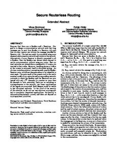
(a)
(b)
(c)
Figure 1: (a) Example topology of 16-node network with 4 partitions of 4 nodes each (16, 4, {4*}). (b) Physical representation of the interconnection between two partitions using “H-Tree” style layout topology for the sub-net bus. (c) Example partitioned floor plan of a 3D system with twelve partitions on three layers.
2 II. ARCHITECTURE A. Network Topology Figure 1 illustrates a 16-node example of our partitioned network topology. In general, networks of this type are characterized by a parameter triple (n, p, {di, i=1,p}), where n is the number of nodes, p is the number of partitions, and di is the number of nodes in the ith partition [7,8]. In this notation, the network shown is figure 1(a) is a (16, 4, {4,4,4,4}) configuration. There is no requirement that all partitions in the network be the same size. However, when they are we use the shorthand notation (n, p, {d*}). Also note that in figure 1(a), the nodes in the network are arranged horizontally with the transmitting and receiving interfaces for each node shown separately on the top and bottom of the diagram respectively. Each of the pair-wise subnets between the partitions in the diagram represents a single, unidirectional, many-to-many interconnection between a single source and single destination partition. The fan-in segment in the source partition connects the transmitters from each node in the source to the backbone and the fan-out segments in each destination partition connect the backbone to a receiver at each node in the receiving partition. Thus, a message originating from any node in the source partition is received by all nodes in the receiving partition. Each node has multiple transceivers, one for each of the subnet buses that connect it to each of the partitions in the network, including its own. Thus, the network is both fully connected and single-hop. The physical implementation of the subnet buses is intended to be fan-in and fan out trees as shown in figure 1(b). The root of the origination partition’s tree connects to the root of a corresponding tree in the destination partition. The source tree consists of a set of fan-in multiplexers and the destination a tree of fan-out buffers. Each partition further defines a local clocking domain with independent control and arbitration for each subnet bus. Figure 1(c) further shows how these partitions can be laid out in a 3D chip stack. It is important to note that since the network is a single-hop fully connected network (i.e., it is flat), it is oblivious to the physical location of the nodes within a partition or the partitions in the system. This means that the partitioning of the network can be done after the system has been floor-planned and that floor-planning can be done based on thermal and physical constraints, without regard for the logical network[9,10,11]. B. Interface Wrapper Logic System nodes are interfaced to the network transparently through an interface wrapper IP-block. Figure 2 shows a block diagram of the interface wrapper logic. The block on the left in this diagram shows the wrapper and host core including the routing multiplexer and subnet bus interfaces. Each wrapper is configured with multiple subnet bus interfaces, one for each pair-wise link to the other partitions in the network. The subnet interfaces are shown in detail in the inset to the right of the figure.
Figure 2: Block diagram of the interface wrapper logic. The logic core at each node communicates with other system nodes by selecting the appropriate subnet bus in the routing multiplexer and accessing the subnet bus via the subnet link controller. Incoming messages are received and buffered at the subnet link controller and passed to the host logic core.
Within the wrapper, routing is simply a matter selecting the transceiver channel corresponding to the destination partition. Outgoing messages from the host logic core are routed to the destination node by the routing multiplexer that selects the subnet bus interface corresponding to the partition of the destination. The bus interfaces consist of access control logic and serializer/de-serializer (serdes) hardware that interfaces to the fan-in and fan-out networks of the pair-wise partition links. Since in this context, routing is simply a matter of selecting the sub-net transceiver corresponding to the destination partition, the only control operation required is the arbitration of the fan-in side of the pair-wise interconnects. C. Distributed Control and Arbitration The enabling technology for this partitioning strategy is a novel, fully distributed control and routing system. This design supports efficient and equitable management of the fan-in networks within each partition. It operates transparently, with minimal control latency. To support a scalable implementation, the arbitration system is designed to avoid the latency associated with a global request/grant style protocol. Instead, we have adopted a greedy, transmit-on-demand, style in which each active node transmits its message on the next cycle without regard to the other traffic in the network. Conflicts are resolved at the selection multiplexers within the fan-in tree. Each sub-tree handles conflicts locally using a simple longest-wait-time algorithm. This assures fair access to the subnet by each node while minimizing the footprint required for the fan-in logic. Figure 3 shows a 4-node binary fan-in tree. The tree is built from smart multiplexers where each data input is accompanied by an “active” control signal and a latency count. Each side of the multiplexer also generates an acknowledgment output to the downstream sub-trees as well as upstream versions of the active control signal and latency count for the selected signal.
3
Figure 3: Block diagram of 4-node fan in tree showing smart multiplexers and control/data signals Local arbitration proceeds as follows. If there is no conflict, the active input is automatically selected and passed to the next level along with its active signal and latency count. In cases of conflict the multiplexor selects the input with the highest latency count (in case of a tie the winner is chosen randomly). Each node repeats transmission on every message cycle until it receives an acknowledgment signal from its local leaf multiplexer. This signal originates at the root of the fan-in tree when the first bit of the message reaches the backbone and propagates backward in parallel with the message transmission. If no acknowledgment signal arrives by the end of the message cycle, the node increments its latency count and retransmits on the next cycle. By always selecting the highest latency input, this algorithm guarantees that the worst-case latency for any message is equal to d-1, where d is the number of cores in the partition. This also limits the wiring complexity for the latency data to log(d). We will show in our simulations that this algorithm also allocates bus bandwidth efficiently and fairly even for traffic loads near saturation.
(i.e. hundreds to thousands of nodes) 3D integrated system. The central design problem is to devise a mechanism within the area constraints of the two logic die that will test the network performance in real time with network traffic corresponding to the execution of a large scale parallel application. We have solved this problem by exploiting the tight integration of a large DRAM in the chip stack. We have combined it with a network implementation that connects simple controllers (rather than full processors) that generate bus transactions based on memory trace data pre-stored in the DRAM. By using this approach we can characterize the real time behavior of the 3D chip network implementation on a “many-core” system without having to implement a complete many-core system and without resorting to unrealistic statistical methods for modeling traffic. In this design, each network transaction serves two purposes. First it emulates the particular traffic patterns corresponding to the target applications, and second each message payload is used to either load additional trace data into the controller memory or to store performance data logged by the controller at each node. Using this approach, our test chip will be able to emulate a variety of parallel programming models. However, our primary effort will focus on emulating a large scale, common memory multicore architecture.
III. 3D IC DEMONSTRATION CHIP DESIGN In this section we describe the design of a test device consisting of 5 chip 3D stack to be fabricated by Tezzaron Inc[12]. The 5 chip stack is organized as shown in figure 4, and consists of a 3-chip memory system on 8x8mm die and two 5x5mm logic die. Our goal is to implement a test platform that will emulate the behavior of the network when configured in a very large scale
Figure 4: 3D Chip stack for demonstration chip
Figure 5: Multi-core SMP emulation architecture.
Figure 5 is a block diagram of the architecture. As shown, the SLI network links local L1 cache emulators at each “processor” node with a set of shared L2 caches. The I/O control nodes are designed to support network access to and from an off-chip controller. We will use these for initial testing and boot up. Our target is to implement 1024 node emulator on the twotier 5x5mm chip. This target is based on an estimate that 80% of each die area will be used for the controller nodes and network interface wrappers and 20% reserved for memory controllers, L2 cache, and other 3D via exclusions. If these numbers change, it may be necessary to reduce the node count
4
Figure 6: Test chip preliminary floorplan.
!
(b)
Figure 7: Network architecture of test chip.
but probably not lower than 512 nodes. (Network size is not restricted to a power of 2. To provide a general mechanism to characterize performance under scaling we will configure the network to include a wide variety of partition sizes, ranging from 128 node partitions down to 4 node partitions. Figure 6 shows a representative partitioning over 512 nodes in four 2mm x 2mm tiles. This preliminary floorplan is only a first approximation, as we do not have complete information yet with regard to the sizes of the memory port via exclusions or their geometry. The figure represents one half of the {1024,28,(128*4,64*4,32*4,16*4,8*4,4*8)} network shown graphically in figure 7. L2 cache nodes are distributed between the partitions with not more than one L2 cache node per partition and preference given to medium to small partition sizes. By embedding smaller networks within this platform, the test chip will allow us to characterize a wide range of network configurations.
(a)
!
(c)
IV. SIMULATION DATA In order to gauge network performance, a software simulation was performed that modeled network behavior for various network configurations and traffic patterns. In this study we have specifically focused on the distributed control and arbitration algorithm for the fan-in networks. This is the key performance limiting aspect of the design. Moreover, since our traffic model used predetermined synthetic traffic patterns (i.e. performance bottlenecks associated with host node loading are not modeled) the performances of individual
(d) Figure 8. (a) shows the average latency per message versus network load for uniform traffic. Each series represents a different partition size. (b) shows the average latency versus network load for a 16-node partition with each series corresponding to a different traffic pattern. (c) shows the maximum latency for any node in same simulation as (a). Figure (d) shows the maximum latencies for the non-uniform traffic simulation shown in (b).
5 partition-to-partition links are independent of one another. With this assumption, we were able to limit our simulation model to the arbitration of a single link between a pair of partitions. A. Network and Traffic Models In our first study, we modeled links between partitions of 16, 64, 256, and 1024 nodes. For each simulation, our traffic model consisted of fixed size messages, length=1, with network traffic loads tested from 10% of subnet backbone capacity up to full saturation of 100%. We modeled several traffic generation patterns across the nodes including both uniform and non-uniform traffic patterns. Non-uniform traffic patterns included three patterns designed to stress particular fan-in sub-trees. These stress points were located at the root, at the leaves, and at an intermediate level of the fan-in tree. In addition, a non-uniform pattern was modeled in which two nodes were highly demanding, targeted to generate approximately 75% of the requests in a network running at near saturation. Each simulation was run for 106 messages times, with data from the first 10% of the simulation discarded as setup time. In each test, the overall network performance was measured as average and worst-case message latency. Additionally, we measured the fairness of bus allocation expressed as the percentage of bus bandwidth allocated to each node versus the expected percentage derived from the request rate built into the traffic model.
(a )
(b)
B. Results Figure 8(a-d) shows our results for average and worst-case message latency studies. Figure 8(a) shows the average latency per message under uniform traffic. Each series in the graph corresponds to a partition size, ranging from 16 to 1024 nodes. Similarly, Figure 8(b) shows the same results for nonuniform traffic patterns in a 16 node partition. Each series in this graph corresponds to a different non-uniform traffic pattern. These results clearly show the efficiency of the control and arbitration system as message latency remains low up to traffic loads near saturation. In addition, average latency values remain very consistent even for large partition sizes. For illustration, compare the average latency values for the 4 partition sizes at 70% utilization. Even though the control system is managing a wide range of partition sizes, the average latency does not vary significantly based on the number of nodes. Figure 8(c) and 8(d) show the worst case latency data for the same simulations. These results show the longest wait time for any node at any point in the simulation. As expected, these results are more sensitive to partition size and network load. However, worst-case latency remains relatively small over a wide range of network utilizations. Fig. 9(a-d) shows the actual percentage of bandwidth allocated to each node compared to the target demand built into the traffic model. For both uniform and non-uniform traffic models, these results illustrate that network allocation consistently matches the demand pattern.
(c)
(d) Figure 9. Fairness measures. (a) shows the actual and expected bandwidth utilizations of the first 16 nodes of the 1,024 node partition simulation under uniform traffic. (b), (c), and (d) show the actual and expected bandwidth utilizations under various non-uniform traffic patterns between two 16 node partitions. See the text for more discussion.
6 Figure 9(a) shows the first 16 nodes of a 1024 node partition under a target load of 90%. Each of the 1024 nodes was equally allocated ~0.088% of the total bandwidth available. Figures 9(b) and 9(c) show two of the non-uniform traffic patterns in a 16 node partition targeting a total traffic load of 92.3%. The traffic patterns modeled introduced imbalance to the fan-in tree at the leaf and root nodes respectively. Specifically, 75% of the demand is evenly split between 8 high-demand nodes, while the other 25% is divided between 8 low-demand nodes. Figure 9(d) shows the final non-uniform traffic pattern in a 16 node partition targeting a total traffic load of 102.4%. In this case, 80% of the demand is evenly split between 2 nodes (nodes 3 and 7), and the other 20% is divided between the remaining 14 nodes. In all of these results, although individual latency reduced the actual utilization by each node, the allocation percentages remained completely consistent with the demand patterns. This is significant given the greedy behavior at the core of the allocation algorithm. It demonstrates that regardless of the greedy behavior, there is no starvation or imbalanced allocation in the system. V. CONCLUSIONS AND FUTURE RESEARCH The architectural paradigm described in this paper shows significant promise for providing a scalable, low-latency system level interconnect for large-scale multicore integrated systems. Although our simulation data is promising, the results from our demonstration chip will be key to demonstrating the overall effectiveness of the network architecture for 3D integrated systems. REFERENCES [1]
[2]
[3] [4]
[5] [6]
[7]
[8]
[9]
S.P. Levitan, “Measuring Communication Structures in Parallel Architectures and Algorithms,” The Characteristics of Parallel Algorithms, L. Jamieson, D. Gannon, R. Douglass, Eds., Cambridge, MA, MIT Press, 1987, pp. 101-137. H.J. Siegel, Interconnection Networks for Large-scale Parallel Processing: Theory and Case Studies, McGraw-Hill, 1990. [Benini02] L. Benini, G. De Micheli,, “Networks on Chips: A New SoC Paradigm,” Computer 35, 1, Jan. 2002, 70-78. T. Y. Feng, “A Survey of Interconnection Networks,” IEEE Computer 14(12), December, 1981, pp 12-27. W. Rhett Davis , John Wilson , Stephen Mick , Jian Xu , Hao Hua , Christopher Mineo , Ambarish M. Sule , Michael Steer , Paul D. Franzon, Demystifying 3D ICs: The Pros and Cons of Going Vertical, IEEE Design & Test, v.22 n.6, p.498-510, November 2005. J. Balfour, W. J. Dally, “Design tradeoffs for tiled CMP on-chip networks,” Proceedings of the 20th Annual international Conference on Supercomputing, 2006, pp 187-198. K. Bernstein, P. Andry, J. Cann, P. Emma, D. Greenberg, W. Haensch, M. Ignatowski, S. Koester, J. Magerlein, R. Puri, and A. Young, “Interconnects in the third dimension: design challenges for 3D ICs,” Proceedings of the 44th Annual Conference on Design Automation, June 2007, pp. 562-567. D.M. Chiarulli, S.P. Levitan, R.G. Melhem, J.P. Teza, G. Gravenstreter; Partitioned Optical Passive Star (POPS) Multiprocessor Interconnection Networks with Distributed Control; IEEE Journal on Lightwave Technology, Vol. 14, No. 7, July 1996, pp. 1601-1612. D. M. Chiarulli, S. P. Levitan, R. G. Melhem, M. M. Bidnurkar, R. M. Ditmore, G. Gravenstreter, Z. Guo, C. Qiao, M. Sakr, J. Teza, Optoelectronic Buses for High-Performance Computing; IEEE Proceedings, Vol. 82, No. 11, Nov. 1994, pp. 1701-1710,. J. Kim, C. Nicopoulos, D. Park, R. Das, Y. Xie, V. Narayanan, M.S. Yousif, and C.R. Das, “A novel dimensionally-decomposed router for
on-chip communication in 3D architectures,” SIGARCH Computer Architecture News 35, 2, June 2007, pp 138-149. [10] V. Krishnan, S. Katkoori, “A 3D-Layout Aware Binding Algorithm for High-Level Synthesis of Three-Dimensional Integrated Circuits”, 8th International Symposium on Quality Electronic Design (ISQED'07), 2007, pp. 885-892. [11] L. K. Scheffer, “CAD implications of new interconnect technologies,” Proceedings of the 44th Annual Conference on Design Automation, June 2007, pp. 576-581. [12] www.tezzaron.com