A Scaleable FFT/IFFT Kernel for Communication Systems using Codesign Approach P. Potipantong1, T. Wiangtong2 and A. Warapishet1 1
Mahanakorn Institute of Microelectronics (MIMs) 2 Electronics Engineering Department Mahanakorn University of Technology, Bangkok 10530, Thailand Phone 0-2988-3666 Ext. 265, 266, Fax 0-2988-4040, Email:
[email protected] Abstract This paper proposes a new architecture of scaleable FFT processor using hardware/software codesign technique for orthogonal frequency division multiplexing (OFDM) systems. The proposed architecture uses a radix-4 butterfly node located on both hardware and software processing elements. We employs an in-place memory strategy, resulting that the butterfly inputs and outputs can be stored at the same memory location without conflict. The memory is partitioned into 4 banks for pipelined computation. In this system, the hardware is modeled by VHDL while the software is written in C. The whole system is completed in Xilinx Vertex-II Pro FPGA that contains IBM PowerPC hard processor. Keywords: Codesign, FPGA, FFT/IFFT, OFDM, SoPC
architecture. It consists of a radix-4 butterfly node working with memory bank structure to satisfy the throughput requirement. An in-place memory-addressing scheme [8] is then exploited to optimize memory size and accessing speed. The overview of system architecture is shown in Fig. 1. There are two processing elements (PEs) ⎯ the first PE is hardware and the second is software. Both are implemented in Xilinx Vertex-II Pro FPGA [6] that contains IBM PowerPCTM 405 RISC processor. The software processor can operate at 350 MHz maximum clock frequency. Application
FFT/IFFT Size
Freq. spacing
WLAN
64
0.3125 MHz
ADSL
2x256
4.3125 KHz
VDSL
2x256x2n, n=0:4
4.3125 KHz
DAB
256x2n, n=0:3
4.065x2n KHz
DVB-T
8192/2048
1.116/4.464 KHz
TFFT
3.2 µ s
231 µ s 231 µ s
31x2n
µs
896/224 µ s
1. Introduction Orthogonal Frequency Division Multiplexing (ODFM) is a multi-carrier modulation scheme resistant to multipath interference and frequency selective fading. OFDM recently has become a key technology for various emerging applications such as wireless LAN (IEEE 802.11a/b/g and HiperLAN2), digital audio/video broadcast (DAB and DVB-T), broadband wireless (MMDS, LMDS), xDSL, and home networking [1] [2]. The modulation/demodulation kernel in OFDM system is computationally intensive FFT/IFFT operations. The size of FFT/IFFT is different depending on various applications which employ OFDM technique as shown in table 1. In this paper, system on a programmable chip (SoPC) for a scalable FFT/IFFT processor using codesign approach is proposed. Hardware/software codesign generally means that the hardware and software are developed at the same time [3], some software functions may be implemented in hardware for additional speed, and some hardware functions may be implemented in software to free up more logic resources. The aim of this paper is try to balance computational work of FFT/IFFT engine in hardware and software, resulting in resource usage optimization. The conventional FFT architecture can be categorized into tree classes [4]: single-memory, dualmemory and pipeline architecture. The design in this paper is based on both single-memory and pipeline
Table 1 FFT/IFFT window size and conversion time of various OFDM applications [1] Hardware and Software Co-design Single-memory architecture PE0 hardware
Main Memory
Single-memory architecture PE1 software
Main Memory
Pipeline architecture
Fig. 1 The proposed FFT/IFFT architecture overview. This paper is organized as follows. Section 2 briefly explains the FFT algorithm. Section 3 describes the proposed FFT/IFFT architecture, also the in-place memory addressing scheme and arithmetic processing elements. Section 4 shows results from the real implementation and performance evaluations. Section 5 concludes the paper and future work. 2. FFT Algorithm The N -point Discrete Fourier Transform (DFT) of a sequence x(n) is defined as N −1
X (k ) = ∑ x(n)WNnk , k = 0...N − 1 ……… (1) n=0
Where x(n) and X (k ) are complex numbers. The
Input Data
x( N )
W
Main Memory 0
Main Memory 1
Bank0
Bank0
Bank1
Bank1
Bank2
Bank2
Interchange
Input Buffer
Output Buffer Bank3
Output Data
Bank3
Fig. 3 The proposed FFT architecture. Stage1 MEM READ
0 N
PE1 Software Radix-4 Butterfly (PowerPC 405)
Multiplexer
In (1), the computational complexity is O( N 2 ) through directly performing the required computation. By using the FFT algorithm, the computational complexity can be reduced to O( N log rN ) , where r means the radix- r . The radix- r FFT can be easily derived from DFT by decomposing the N -point DFT into the set of recursively related r -point transform, if the number of inputs x(n) is powers of r .
Interchange
(2)
PE0 Hardware Radix-4 Butterfly
Multiplexer
=e
⎛ 2π nk ⎞ ⎛ 2π nk ⎞ = cos ⎜ ⎟ − j sin ⎜ ⎟ N ⎝ ⎠ ⎝ N ⎠
Interchange
W
⎛ 2π nk ⎞ − j⎜ ⎟ ⎝ N ⎠
Twiddle Factor (ROM)
Multiplexer
nk N
can be defined as:
Interchange
twiddle factor W
then responsible for the first log 4 ( N ) − 1 stage of the FFT.
Multiplexer
nk N
INTERCHANGE
Stage 2
ADD1/ADD2
Stage3
MULT1
Stage4
MULT2
Stage5 INTERCHANGE
MEM WRITE
Stage 1 MEM READ
INTERCHANGE
X (n)
Fig. 4 The hardware pipeline diagram. N⎞ ⎛ x⎜ n + ⎟ 4⎠ ⎝
WNn
N⎞ ⎛ X ⎜n+ ⎟ 4⎠ ⎝
N⎞ ⎛ x⎜ n + ⎟ 2⎠ ⎝
WN2n
N⎞ ⎛ X ⎜n+ ⎟ 2⎠ ⎝
3N ⎞ ⎛ x⎜n + ⎟ 4 ⎠ ⎝
WN3n
3N ⎞ ⎛ X ⎜n+ ⎟ 4 ⎠ ⎝
Where n = 0,1,..., ( N / 4) − 1
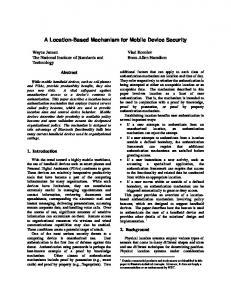
Fig. 2 Radix-4 DIF butterfly signal flow.
There are two basic types of FFT algorithm: decimation-in-time (DIT) and decimation-in-frequency (DIF). The radix-2 FFT algorithm is popular in FFT processor design due to its simplest form in all FFT algorithms. However its computational complexity is twofold comparing to the redix-4 algorithm. In order to save the number of complex multiplications, we choose radix-4 algorithm to suit with different window sizes of various applications. Fig. 2 shows the signal flow of a radix-4 DIF butterfly. 3. The Proposed FFT Architecture
Fig. 3 shows the proposed codesign architecture for the scaleable FFT/IFFT process. By using hardware and software codesign approach, we can reduce power consumption and resource in hardware. For an N - point FFT that consists of log 4 ( N ) stages, Cooley and Tukey [7] show that there are trivial multiplications in the last stage where all twiddle factors are equal to 1. Therefore, the last stage of the FFT is multiplier-free, and it should be implemented in software processing. The hardware processing element (PE0) is
The merit of this structure is that while PE1 computes the last stage, PE0 can begin processing the next frame of data. Each PE contains a single radix-4 butterfly node to processes complex data samples at a time, which requires N / 4 times on each stage. For example, if N =1024, there are 5 stages and one stage requires 256 times of the butterfly process. PE0 will process data for stages 0-3, while PE1 only computes stage 4. In this system, the complex fixed-point data is represented in 32 bits for real and imaginary parts (each equally engages 16 bits). This architecture can either compute a single data frame (= window size) or streaming data. At any given time, while the current frame is being processed, the next frame is begin written to memory and the previous frame’s results are begin retrieved from memory. All input and output data are presented in natural and not bitreversed order. For example, the process begins with the first frame of data is loaded into the memory (Frame 0). While the process begins on Frame 0, a new set of data (Frame 1) is written into memory. Once the process is done, the results of Frame 0 can be read out and Frame 1 can be instantly computed. At that time, Frame 2 is being written to the input memory again. Our butterfly processor implemented in hardware PE is able to calculate 4 complex inputs in every cycle using pipelined fashion. As shown in Fig. 4, the processors datapath has 5 pipeline stages. The first pipeline stage is separated into two half-cycle stages. In the first half, the inputs of butterfly are read from the memory. In the second half, four butterfly inputs themselves are interchanged for the correct positions before being processed. In stages two, two stages of additions show in Fig. 3 are performed. In stages three and four, the multiplications of the real and imaginary components are performed. Stage five completes the complex
multiplication and the butterfly results are interchanged to be stored to the correct banks. To implement the inverse FFT (IFFT), it can be done by conjugating input data before applying on the first stage. Also the output data must be conjugated after the last stage. When the forward FFT is being computed, the conjugators will simply act as pipeline registers.
The hardware implementation of a radix-4 DIF butterfly is show in Fig. 6. One butterfly node requires 8 adders and 4 multipliers. The twiddle factors are precomputed and stored in an on-chip Block-ROM. The complex multiplication is implemented using four 16×16-bit hardware multipliers and two adders. All are written in VHDL and operates in pipelined fashion as described previously.
3.1 The In-place Memory Addressing x(0)
0
0
0
0
Bank1
0
1
0
Bank2
0
2
0
8
Bank3
0
3
0
12
Bank1
1
4
0
1
Bank2
1
5
1
Bank3
1
6
1
2
8
Bank0
1
7
2
3
13
Bank2
2
8
3
0
Bank3
2
9
4
2
4
5
5
6
2 6
7 Bank0
2
10
4
10
Bank1
2
11
6
14
Bank3
3
12
0
3
Bank0
3
13
3
Bank1
3
14
6
11
Bank2
3
15
9
15
7
8
Fig. 5 The data flow graph of a in-place 16-point FFT. Data Bank Addrs 0 0 0 1 1 0 2 2 0 3 3 0 4 1 1 5 2 1 3 1 6 7 0 1 8 2 2 9 3 2 10 0 2 1 2 11 12 3 3 0 3 13 14 1 3 15 2 3
Data Bank Addrs 16 1 4 17 2 4 18 3 4 19 0 4 20 2 5 21 3 5 22 0 5 23 1 5 24 3 6 25 0 6 26 1 6 27 2 6 : : : :
The proposed architecture is able to compute smaller length FFTs by changing/scaling to memory addressing adequate for a smaller length transform. For example, the architecture for 1024-point FFT is applicable for 256-point FFT, 64-point FFT and 16-point FFT. 3.2 Hardware Processing Element
X (1)
wx
X (2)
wx
X (3)
−j
x(3)
Fig. 6 Implementation of radix-4 butterfly node. 3.3 Software Processing Element
In this system, IBM PowerPCTM 405 processor represent software processing element. The software architecture consists of a PowerPC hard processor core, a processor local bus (PLB), on-chip peripheral bus (OPB), PLB-to-OPB bridge, four 64-bit general purpose input/outputs (GPIOs) for inputting and outputting butterfly data, and 2-bit GPIO for control signals (see Fig.7). The source code of butterfly operation is written in plain C programming language. All are developed using Xilinx embedded development kit (EDK) tools. The PowerPC processor computes only the last stage of the FFT/IFFT processor since it does not need complex multipliers for the twiddle factors. When the processor is received a flag signal from the control-unit implemented in hardware, the processor will taken a four data words from the main memory through GPIO (butterfly leg 0-3) to process. The results of software processing element are sent out to the in-place memory. Instruction, Data Block RAM
Data Bank Addrs : : : : 244 3 61 245 0 61 246 1 61 247 2 61 248 0 62 249 1 62 250 2 62 251 3 62 252 1 63 253 2 63 254 3 63 255 0 63
Table 2. The address assignment of a 256-point FFT.
w
Processor Local Bus (PLB).
IBM PowerPCTM 405 Core
PLB to OPB Bridge
On-chip Peripheral Bus (OPB).
64-bit GPIO (0) 32
64-bit GPIO (1) 32
64-bit GPIO (2)
64-bit GPIO (3)
32
32
32
Butterfly Leg 0
Butterfly Leg 1
32 32
Butterfly Leg 2
2-bit GPIO (4)
32
Butterfly Leg 3
start
Address Bank0
x(1) x(2)
finish
We adopt the in-place memory addressing scheme for the radix-4 FFT algorithm [8]. Without memory conflicts, Fig.5 shows the example of addressing scheme for a 16-point FFT. For the concurrent read and write operations of each radix-4 butterfly node, the memory is partitioned into 4 banks. As the example in Fig. 5, 4 inputs can be read from different banks and 4 outputs can be written to different banks for all butterfly operations (1 – 8). Table 2 shows the address assignment for a 256-point FFT.
X (0) x
Control Signal
Fig. 7 Software PE architecture. 4. System Implementation and Results
The system is implemented on the Memec design Virtex-II Pro™ (P7-FF672) development kit that
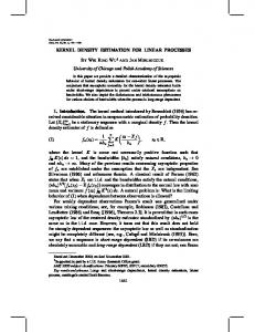
provides a complete development platform for designing and verifying applications based on the Xilinx Virtex-II Pro FPGA family. After place-and-route process, the resource utilization of 256-point FFT/IFFT is concluded in table 3, and the results compared to MATLAB are shown in Fig. 8. From implementation reports, the maximum operating frequency of hardware PE is 65MHz (minimum period: 15.213ns). At this speed, the proposed architecture can complete 256-point in 10.8 µ s , 64-point in 2.4 ns and 16-point in 640 ns which is much enough for requirements of OFDM applications as seen on Table 1. This is only conceptual proof of the real implementation due to the limit of the available logic resource on the chip. For wider window size such as 8192/2048 in DVB-T system, this design approach is believingly applicable. FPGA Device: Xilinx 2vp7ff 672-6 Number of Slices: Number of Slice Flip Flops: Number of 4 input LUTs: Number of bonded IOBs: Number of BRAMs: Number of MULT18X 18s: Number of GCLKs: Number of PPC405s:
1302 1246 2332 35 22 16 1 1
out of out of out of out of out of out of out of out of
4928 26% 9856 12% 9856 23% 396 8% 44 50% 44 36% 16 6% 1 100%
Table 3. Resource utilization of 256-point FFT/IFFT. 1 0.5 0 -0.5 -1
0
50
100 150 [a] Input Signal (256-point)
200
40 30 20 10 0
0.1
0.2
0.3
0.4 0.5 0.6 [b] Result: MATLAB FFT function
0.7
0.8
6. References
[1] IEEE 802.11a-1999, “IEEE standard for Wireless LAN Medium Access Control and Physical Layer Specification”, ISO/IEC 8802-11:199 / Amd 1:2000(E) [2] Van Nee, R., Prasad, R., “OFDM for Wireless Multimedia Communications”, Artech House Publishers, 2000 [3] De Micheli, G, “Computer-aided hardware -software codesign”, IEEE Micro, Vol. 14, pp. 10-16. 1994 [4] B. M. Bass, “A low power, high performance, 1024point FFT processor,” IEEE J. Solid-State Circuits, vol. 34, pp.380-387, Mar. 1999. [5] W. Li and L. Wanhammar, “A pipeline FFT processor,” in Proc. IEEE Workshop on Signal Processing Systems, 1999, pp. 654-662 [6] Xilinx, “Vertex-II Pro Platform FPGA Handbook”, Xilinx Inc., Oct. 2002 [7] J.W. Cooley and J.W. Tukey, “An algorithm for the machine calculation of complex Fourier series” Math. Comp., 19:297–301, April 1965. [8] L. G. Johnson, “Conflict free memory addressing for dedicated FFT hardware,” IEEE Trans. Circuits Syst. II, vol. 39, pp. 312-316. May 1992.
250
50
0
(PowerPC). Based on our implementing experience, one potential problem in the proposed system would be communication time between hardware and software which is done through GPIO ports. The improvement on this bottle neck is partly future work which aims to implement a complete OFDM system.
0.9
1
50 40
Panan Potipantong receive the B.S. and M.S. degree in computer engineering from Mahanakorn University of Technology, Bangkok, Thailand, in 2000 and 2003, respectively. His research interests include digital system design, hardware and software codesign, embedded system.
30 20 10 0
0
0.1
0.2 0.3 0.4 0.5 0.6 0.7 0.8 [c] Result: Proposed FFT Processor (Xilinx ChipScorp Pro)
0.9
1
Fig. 8 256-point FFT outputs comparing with MATLAB 5. Conclusions and future work
OFDM technique is increasingly important for many modern communication systems. Using only software can not completely handle the high computational process such FFT/IFFT core in OFDM. Combining hardware in the system is therefore inevitable. This paper presents an idea of implementing a scaleable FFT/IFFT core using codesign approach. The system is on a programmable chip, so-called SoPC, consisting of both hardware (FPGA fabric) and software
Theerayod Wiangtong received the B.S. degree in electronics engineering from king Mongkut’s Institute of Technology Ladkrabang, Bangkok, Thailand, in 1993, and the M.S. degree in satellite communication from University of Surrey, UK in 1995, and the Ph.D. degree in digital system design and codesign from Imperial College London in 2004. Apisak Worapishet received the B.S. degree in electronics engineering from king Mongkut’s Institute of Technology Ladkrabang, Bangkok, Thailand, in 1991, and the M.S. degree in electronics engineering from University of New South Wales, Sydney Australia, in 1995, and the Ph.D. degree in electronics engineering from Imperial College of Science, Technology and Medicine, London, England, in 2000.