A Semantic Network-Based Design Methodology for XML Documents LING FENG University of Twente, The Netherlands ELIZABETH CHANG University of Newcastle, Australia and THARAM DILLON La Trobe University, Australia
The eXtensible Markup Language (XML) is fast emerging as the dominant standard for describing and interchanging data among various systems and databases on the Internet. It offers the Document Type Definition (DTD) as a formalism for defining the syntax and structure of XML documents. The XML Schema definition language, as a replacement for the DTD, provides more rich facilities for defining and constraining the content of XML documents. However, it does not concentrate on the semantics that underlies these documents, representing a logical data model rather than a conceptual model. To enable efficient business application development in large-scale electronic commerce environments, it is necessary to describe and model real-world data semantics and their complex interrelationships. In this article, we describe a design methodology for XML documents. The aim is to enforce XML conceptual modeling power and bridge the gap between software development and XML document structures. The proposed methodology is comprised of two design levels: the semantic level and the schema level. The first level is based on a semantic network, which provides semantic modeling of XML through four major components: a set of atomic and complex nodes, representing real-world objects; a set of directed edges, representing semantic relationships between the objects; a set of labels denoting different types of semantic relationships, including aggregation, generalization, association, and of-property relationships; and finally a set of constraints defined over nodes and edges to constrain semantic relationships and object domains. The other level of the proposed methodology is concerned with detailed XML schema design, including element/attribute declarations and simple/complex type definitions. The mapping between the two design levels is proposed to transform the XML semantic model into the XML Schema, based on which XML documents can be systematically created, managed, and validated. Categories and Subject Descriptors: H.2.1 [Information Systems]: Database Management— logical design General Terms: Design, Languages
This work was completed while L. Feng was at Infolab, Tilburg University in the Netherlands. Author’s addresses: L. Feng, Dept. of Computer Science, University of Twente, The Netherlands; email:
[email protected]; E. Chang, Department of Computer Science & Software Engineering, University of Newcastle, Australia; email:
[email protected]; T. Dillon, Department of Computer Science & Computer Engineering, La Trobe University, Australia; email: tharam@ cs.latrobe.edu.au. Permission to make digital/hard copy of part or all of this work for personal or classroom use is granted without fee provided that the copies are not made or distributed for profit or commercial advantage, the copyright notice, the title of the publication, and its date appear, and notice is given that copying is by permission of the ACM, Inc. To copy otherwise, to republish, to post on servers, or to redistribute to lists, requires prior specific permission and/or a fee. ° C 2002 ACM 1046-8188/02/1000-0390 $5.00 ACM Transactions on Information Systems, Vol. 20, No. 4, October 2002, Pages 390–421.
Semantic Network-Based Design Methodology
•
391
Additional Key Words and Phrases: XML, design methodology, conceptual modeling, semantic network, XML Schema
1. INTRODUCTION XML was introduced in 1996 to overcome the deficiencies of HTML. It is much more powerful than HTML, allowing structural and semantic markups, allowing presentation of specific instructions using style sheets, and allowing the incorporation of metainformation and somewhat more flexible link management than HTML. It builds on the principles and conventions of the Standard Generalized Markup Language (SGML) [Bryan 1992], and provides a simple yet powerful mechanism for information storage, processing, and delivery. Nowadays, XML has become an increasingly important data format for storing and interchanging data among various systems and databases on the Internet. As a new markup language that supports user-defined tags, and encourages the separation of document content from its presentation, XML is able to automate Web information processing, in particular for data exchange and interoperability which are major issues in business-to-business electronic commerce [Consortium 2000a,d]. In data exchange applications, whenever composite data must be exchanged between two programs, XML serves as a suitable format for making the data self-describing. XML is thus, in part, a data representation language that lets us describe data and create vocabularies to exchange information. In addition, XML separates data from presentation, making them reusable. The Document Type Definition (DTD) offered by XML can be used as a formalism for defining the syntax and structure of XML documents. The XML Schema definition language, as a replacement for the DTD, provides more rich facilities for defining and constraining the content of XML documents [Sahuguet 2000]. However, in Web applications, writing XML is a lot more work than writing HTML because XML requires more knowledge about the relationships between elements rather than the content itself. On the other hand, to enable efficient business application development in large-scale electronic commerce environments, current XML lacks the modeling power in describing real-world data and their complex interrelationships, and thus providing the objects’ necessary semantics. These factors highlight the need for a design methodology to provide a foundation for the design and development of XML documents. As XML bears a close similarity to semistructured data models [Bradley 1998; Buneman et al. 2001; Beeri and Tzaban 1999], one current trend in the literature is to apply data models developed for semistructured and unstructured data to XML [Goldman et al. 1999]. The Object Exchange Model (OEM) developed at Stanford University is a simple, self-describing, nested object model that represents semistructured data by a labeled directed graph [Goldman and Widom 1997; Buneman et al. 1996]. The OEM model was further migrated to work with XML [Goldman et al. 1999], where OEM’s object corresponds to element, and OEM’s subobject relationship mirrors element nesting in XML. ACM Transactions on Information Systems, Vol. 20, No. 4, October 2002.
392
•
L. Feng et al.
When we compare the OEM-based XML data model with the one described in this article, although both adopt graphic notations, there is a fundamental difference. The former models XML documents at the instance level. It does not give an instance-independent description of the data. In contrast, we model XML data at the concept level through a set of semantic relationships including aggregation, generalization, association, and of-property, and various constraints defined on objects and their relationships. W3C provides an XML Data Model to visualize the structures of XML documents [Consortium 2000c]. This model provides no more than a baseline on which more complex models can be built. It presents an XML document as a linearization of a tree structure. This model focuses more on the syntactic structure of XML documents; it does not address semantic modeling issues for XML documents. The Resource Description Framework (RDF) is part of the result of the W3C Metadata Activity. The aim of RDF is to provide a robust and flexible way to standardize the definition and use of metadata, descriptions of Web-based resources [Consortium 2000b]. RDF emphasizes facilities to enable automated processing of Web resources. It is a foundation for processing metadata so as to provide interoperability between applications that exchange machineunderstandable information on the Web. The broad goal of RDF is to define a mechanism for describing resources that makes no assumptions about a particular application domain, nor predefines the semantics of any application domain. In general, RDF is a model of metadata. It uses XML to specify metadata semantics. In this sense, RDF and XML are complementary. Since RDF aims to provide a common, generic, and domain-neutral information description framework, its modeling primitives are not as rich as a semantic network, which captures more semantics such as different kinds of interrelationships among real-world entities, together with different constraints enforced over these interrelationships. Also, as XML currently gains increasing importance in data exchange and dissemination on the Internet, for a specific application, it would be important and useful to build up its semantic model, and then convert it into XML Schema. Recently, Conrad et al. [2000] proposed conceptually modeling XML DTDs and thus classes of documents on the basis of the Unified Modeling Language (UML). The idea was to use essential parts of static UML to model XML data schemata. The mapping between the static part of UML specification (i.e., class diagrams) and XML DTDs was developed. To take advantage of all facets that DTD concepts offer, the authors extended the UML language in a UML-compliant way. An object-oriented method was further presented in Xiao et al. [2001b,a] to conceptually model XML Schema. Our work is distinguished from the above ones in the following aspects. First, we focus on the design methodology for XML documents, which is comprised of two design levels, that is, the semantic level and the schema level. Second, our transformations from the semantic level to the schema level target the most general semantic relationships between objects, and are thus not limited to UML. In particular, we take different perspectives regarding these semantic relationships (e.g., strong/weak adhesion, ordered composition, ACM Transactions on Information Systems, Vol. 20, No. 4, October 2002.
Semantic Network-Based Design Methodology
•
393
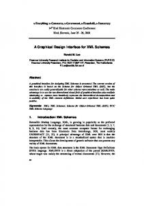
Fig. 1. A two-level design approach.
homogeneity/heterogeneity and exclusion in aggregation relationships, inheritance, and overriding in generalization relationships, and strong/weak adhesion and exclusion in association relationships), and various constraints on objects into consideration, and examine how they can be realized in the XML Schema. Our current article highlights an XML design methodology based on a semantic network. The aim is to enforce XML conceptual modeling power, making it easier to create, manage, retrieve, and validate the semantics of the XML schema. The proposed methodology is based on two design levels: a semantic level and a schema level, as shown in Figure 1. We first present a way to semantically model XML using a semantic network. It has four major components: a set of atomic and complex nodes, representing real-world objects; a set of directed edges, representing semantic relationships between the objects; a set of labels denoting different types of semantic relationships, including aggregation, generalization, association, and of-property relationships; and finally, a set of constraints defined over nodes and edges to constrain semantic relationships and object domains. We then examine the mapping from the XML semantic level to the corresponding XML schema level, which is mainly concerned with detailed XML element/attribute declarations and simple/complex type definitions. Based on the generated XML Schema, XML instance documents can then be systematically constructed and controlled. With the proposed methodology, it is possible to combine software development with the XML data schemata. This will enable one to improve reuse at both document and application design levels, and support the generation of common application components. The remainder of the article is organized as follows. Section 2 presents a semantic network model for XML. Section 3 describes the mapping process from the XML semantic level to the XML schema level. Section 4 concludes the article with a brief discussion of future work. 2. XML SEMANTIC LEVEL In this section, we first provide a brief review of XML document structure, and then describe a semantic data model for XML based on a semantic network. 2.1 XML Document Structure XML is concerned with describing the structure of documents that are stored in electronic format, in a form that is accessible to both people and computer ACM Transactions on Information Systems, Vol. 20, No. 4, October 2002.
394
•
L. Feng et al.
Fig. 2. A hierarchical document structure example.
software. An XML format data file contains a mixture of document texts and XML markups, which organize and identify the components of a document. XML markups build on the concept of macro-based typesetting languages. A start-tag and an end-tag, together with the data enclosed by them, comprise an element. XML elements may contain further embedded elements, leading to a hierarchical document structure. An example of this hierarchy is shown in Figure 2. A Book element may contain a Title element and a Content element. The Content element is comprised of a number of Chapter elements, and each Chapter element contains a number of Paragraph elements. In general, each specified element must be a container element or empty. Container elements may contain text, child elements, or a mixture of both. The use of child elements can be controlled in a Required, Optional, or Repetition way. For example, every book must have a title, so the Book element must have a Title child element. This is an example of Required. A child element may be an option. This is called Optional. A child element may be repeatable like the Chapter element and Paragraph element. Each element can be associated with one or more attributes. An attribute, consisting of an attribute name and an attribute value, provides refined information about an element. An XML document is usually associated with a type specification called Document Type Definition containing user-defined element types and attribute specifications that allow one to describe the meaning of the content. In the early stages of XML development, there were several proposals to introduce XML Schema. The XML Schema offers a replacement of XML DTD, with the purpose of constraining and documenting the meaning, usage, and relationships of their constituent parts such as permissible data types, elements, and their contents, attributes, and attribute values [Consortium 2001]. The schema definition language, which is itself represented in XML, considerably extends the capabilities of XML DTD for defining and constraining the content of XML documents. An XML Schema is usually comprised of a set of schema components, such as type definitions and element declarations. They can be used to assess the validity of well-formed element information items. There are 12 kinds of schema components in total, falling into three groups. The most used components include simple type definitions, complex type definitions, attribute declarations, and element declarations. ACM Transactions on Information Systems, Vol. 20, No. 4, October 2002.
Semantic Network-Based Design Methodology
•
395
2.2 Coupling Semantic Networks with Hierarchical Structures As models can help users understand the system by abstracting away some of the details, the choice of what to model has an enormous effect on the understanding of the problem and the shape of the solution [Booch et al. 1998]. Here we utilize a semantic network to convey the semantics carried by the XML hierarchical data structures. At first glance, XML and semantic networks seem to be two different things, since XML is frequently used to represent highly hierarchical information and the latter are intended for the representation of the relationships between different objects. Hierarchical data structures are excellent for organizing data because they have an unambiguous point of view, making their semantics very powerful. Semantic nets, on the other hand, are useful because they allow us to establish and express many different data structures and relationships explicitly from the same data. Because each of them is important, transforming a semantic network into a hierarchical structure will let us create XML documents from a semantic network model automatically. We also want to do the reverse, which will let us import XML documents into a database that is based on a semantic data model. By understanding the correspondence between the semantic data model and XML, developers can begin to work with XML in a similar fashion to the way they work with semantic data models. Parsers and programs can be written to transparently move data back and forth between semantic data models and XML documents without losing or altering the semantics associated with the data. In this article, we focus on the transformation from the semantic network model into XML Schema (as depicted in Figure 1) in order to help users conveniently generate XML documents by concentrating on the content of the documents and the relationships inside them. 2.3 A Semantic Network Model A semantic network is an oriented diagram consisting of a series of nodes that are connected to each other through directed labeled edges. In addition, constraints can be defined over these nodes and edges. At an abstract level, a semantic network model consists of the four components: — A set of nodes Node , representing real-world objects; — A set of directed edges Edge , representing semantic relationships between the objects; — A set of labels Label , denoting different types of semantic relationships; and — A set of constraints, Constraint , defined over the nodes and edges. 2.3.1 Nodes. We categorize nodes into basic nodes and complex nodes. Basic nodes have no edges emanating from them. They are the leaf nodes in the semantic network diagram. Complex nodes are the internal nodes in the network diagram. Each complex node has one or more labeled directed edges emanating from it, each associated with a label, and each going to another node. Figure 3 gives a running example of a semantic network used in the article, where complex nodes are denoted using a box and basic nodes are denoted ACM Transactions on Information Systems, Vol. 20, No. 4, October 2002.
396
•
L. Feng et al.
Fig. 3. A semantic network example.
using a dot. Some complex nodes are like ORDER, PERSON, ITEMS, and BOOK, and so on, each of which has one or more outgoing edges. Basic nodes include FirstName, Addresses, Isbn, and so on. Cycles. An important issue worth mentioning here is that a semantic network may have cycles. For instance, a BOOK, appearing in one ORDER, may be associated with some other ORDERs; that is, a book may be ordered by several customers. To facilitate the transformation from semantic networks to XML Schema which is addressed in the following section, we propose to break the cycles, and turn a cyclic directed graph (i.e., an original semantic network) into an equivalent acyclic directed graph without loss of semantics. Suppose we have a cycle (n1 , n2 , n3 , . . . , nm ), where node n1 points to node n2 , n2 points to n3 , and so on, and nm points back to n1 again. To avoid such cyclic references, we allow a new leaf (basic) node nx to be named. It serves as the al ias or representative of node n1 , so that node nm can point to nx instead of n1 . To ensure equivalent transformation, we apply the referential integrity constraint on the newly introduced leaf node nx , the key of which refers to node n1 . Figure 4 shows how a cycle in Figure 3 is broken and presented in an acyclic manner. Here another question arises from such a transformation: where to break a cycle? In other words, how to identify the root node with which a cycle starts. Concrete applications play an important role in this situation. If the main theme of the application is about ni , say, ORDER in our example, then we put ORDER as the root node, whose existence preced es other nodes in terms of the application. In contrast, if the application centers around books, then the BOOK node can be treated as the root. Normally, a link connecting two nodes of the generalization relationship is not a suitable candidate to break up, since the two nodes together convey integral information. Each basic node in the semantic network has a simple content, containing values comprised from the domains of basic data types (e.g., string, integer, etc.). ACM Transactions on Information Systems, Vol. 20, No. 4, October 2002.
Semantic Network-Based Design Methodology
•
397
Fig. 4. A cycle conversion example. ACM Transactions on Information Systems, Vol. 20, No. 4, October 2002.
398
•
L. Feng et al.
Let D1 , . . . , Dn be a series of basic data types, whose domains are denoted n dom (Di ). dom(D1 ), . . . , dom(Dn ). Let DOM = ∪i=1 Definition 2.1.
A simple content of a basic node can be
1. an atomic value sc ∈ DOM; or 2. a constructional value sc, where — sc = {sc1 , sc2 , . . . , sck }, called a set value, where ∃i(1 ≤ i ≤ n) (sc1 , . . . , sck ∈ dom(Di )) ∧ ∀i ∀ j (1 ≤ i, j ≤ k) (i 6= j ⇔ sci 6= sc j ); or — sc = (sc1 , sc2 , . . . , sck ), called a bag value, where ∃i(1 ≤ i ≤ n) (sc1 , . . . , sck ∈ dom(Di )); or — sc = , called a list value, where ∃i(1 ≤ i ≤ n) (sc1 , . . . , sck ∈ dom(Di )), and all elements in sc are in a prescribed order, that is, for any two list values sc = and sc0 = , (sc = sc0 ) if and only if ∀ j (1 ≤ j ≤ k)(sc j = sc0j ); or — sc = [sc1 |sc2 | . . . |sck ], called a union value, where ∀ j (1 ≤ j ≤ k) (sc j ∈ DOM). Among the constructional values for basic nodes, a set value is an unordered collection that does not allow duplicates. The values that belong to a set are all unique. A bag value is similar to a set value, except that it allows duplicate values to exist. Therefore, it is an unordered collection that allows duplication. A list value is an ordered collection that allows duplicates. A union value allows any member of a collection as the returning value. Except for a union value, all members in a constructional value must be of the same basic type. On the contrary, the content of a complex node, which is called the complex content accordingly, refers to some other nodes through directed labeled edges. Each edge connects two nodes, with a label stating the relationship between the two nodes. Before giving the formal definition of complex content, we first define the concepts of connection, connection cluster, and connection cluster set using the cableset approach presented in Morgado [1986] and Shapiro [1991]. Definition 2.2. A connection of a node n ∈ Node is an ordered pair < l , n0 >, where l is a label in Lable and n0 is a node in Node , representing that node n is connected to node n0 via relation l . Definition 2.3. A connection cluster of a node n ∈ Node is an ordered pair < l , ns >, where l is a label in Lable and ns is a set of nodes in Node , representing that node n is connected to each node in ns via relation l . Definition 2.4. A connection cluster set of a node n ∈ Node is a set of connection clusters, {< l 1 , ns1 >, . . . , < l k , nsk >}, where ∀i ∀ j (1 ≤ i, j ≤ k) (i 6= j ⇔ l i 6= l j ). Definition 2.5. set.
A complex content of a complex node is a connection cluster
Definition 2.6. A node n ∈ Node is a 4-tuple (nid , nname , ncategory , ncontent ), consisting of a unique node identifier nid , a node name nname , a node category ACM Transactions on Information Systems, Vol. 20, No. 4, October 2002.
Semantic Network-Based Design Methodology
•
399
ncategory indicating whether the node n is basic or complex, and a node content ncontent . If ncategory = “basic,” the node has a simple content; otherwise, it has a complex content. Let N B and NC be the set of basic nodes and complex nodes, respectively, where N B ∩ NC = ∅ and N B ∪ NC = Node . Example 2.1. In Figure 3, FirstName, MiddleName, and LastName are basic nodes, each of which has a simple content drawn from the atomic String data type. Addresses is also a basic node whose simple content is a constructional set value, indicating each person can have multiple contact addresses. The complex node PERSON is connected to a set of nodes {FirstName, MiddleName, LastName, Addresses} through four outgoing edges, each labeled by relationship “a” (denoting aggregation). Thus the complex content of node PERSON is {< “a”, {FirstName, MiddleName, LastName, Addresses} >}. As the complex node ORDER links to nodes {PERSON, ITEMS, DELIVERY, Remark} with relationship “a”, to node INVOICE with relationship “s” (denoting association), and to node OrderId with relationship “ p” (denoting of-property), the complex content of ORDER is {< “a”, {FirstName, MiddleName, LastName, Addresses} >, < “s”, {INVOICE} >, < “ p”, {OrderId} > }. 2.3.2 Edges. Each edge in the model links two nodes, representing their semantic relationship. This binary relationship expresses static interobject connection, and hence captures the structural aspects of real-world objects. Here, we organize different nodes mentioned above according to four link types, namely, generalization, aggregation, association, and of-property relationships. — A generalization is a relationship between a general concept and a more specific concept. It is sometimes called an “is-a” relationship, which is often used to show inheritance between objects. — An association is a structural relationship, specifying that objects of one kind are connected to objects of another. Given an association connecting two objects, we can navigate from one to another, and vice versa. A plain association between two objects represents a structural relationship between peers, meaning that both are conceptually at the same level, and no one is more important than the other. — An aggregation is a composite relationship, in which a composite object (“whole”) consists of some component objects (“parts”). This kind of relationship represents a “part-of ” relationship. Aggregation is often treated as a kind of association. But objects in the aggregation relationship are not conceptually at the same level. This feature distinguishes the aggregation relationship from the general association relationship [Dillon and Tan 1993; Rahayu et al. 1996]. — The of-property relationship specifies the subsidiary attribute of an object. Here, we use symbols g , s, a, p to denote generalization, association, aggregation, and of-property relationship, respectively. Thus, Label = { g , s, a, p}. ACM Transactions on Information Systems, Vol. 20, No. 4, October 2002.
400
•
L. Feng et al.
Definition 2.7. An edge e ∈ Edge is a triple (elabel , esource node , etarget node ), consisting of a label elabel ∈ Label stating the link type, the source node of the edge esource node ∈ Node , and the target node of the eedge etarget node ∈ Node . An edge e label can also be pictorially denoted as “esource node −→ etarget node .” p
Example 2.2. In Figure 3, the edge “BOOK−→ Isbn” specifies that BOOK a node has a property Isbn.1 The edge “PERSON −→ FirstName” indicates that PERSON is a “whole” object, and one of its “part” objects is FirstName. “ITEM g −→ BOOK ” represents that the ITEM node is more general than the BOOK node. The fact that each ORDER may have one or more associated INVOICEs s is expressed through the edge “ORDER −→ INVOICE.” elabel
Definition 2.8. A well-formed edge “esource node −→ etarget node ” is an edge that satisfies the following syntactic conditions. [Condition 1] If the link type is of-property, the source is a complex node and the target is a basic node. That is, (elabel = p) implies (esource node ∈ NC ) and (etarget node ∈ N B ); [Condition 2] If the link type is generalization or aggregation or association, the source is a complex node. That is, (elabel ∈ { g , a, s}) implies (esource node ∈ NC ) and (etarget node ∈ Node ). In the article, all the edges under discussion are assumed to be well-formed. Based on the notions of nodes and edges, we further introduce the concepts of path, original path, and node depth as follows. Definition 2.9. A path from node n1 to node nk is a sequence n1 , n2 , . . . , nk , where n1 , n2 , . . . , nk ∈ Node , and for any two consecutive nodes, ni and ni+1 (1 ≤ i ≤ k − 1), there exists an edge ei (l , ni , ni+1 ) ∈ Edge . The path can also be pictorially denoted as “γ ,→ (n1 , n2 , . . . , nk ).” We call n1 and nk the starting node and ending node of the path, respectively. The path is said to go through node ni (1 ≤ i ≤ k). The length of a path is the total number of nodes that the path goes through; that is, k for the path “γ ,→ (n1 , n2 , . . . , nk ),” denoted as length(γ ) = k. Definition 2.10. A path from node n1 to node nk , γ ,→ (n1 , n2 , . . . , nk ), is an original path, if and only if the starting node n1 has no incoming edges. Note that as no cycles exist in the semantic network after the transformation, as described in Section 3.3.1, for any path, we can find a starting node and also an ending node. Example 2.3. “γ ,→ (ORDER, PERSON, FirstName)” is a path and also an original path. The length of the path is 3. The path “γ ,→ (ITEM, BOOK, CONTENT, Chapter)” is not original, since its starting node ITEM has an incoming edge. With the notion of original path, we can define the depth of a node as follows. 1 For
simplicity, here, we refer to a specific node using the node name.
ACM Transactions on Information Systems, Vol. 20, No. 4, October 2002.
Semantic Network-Based Design Methodology
•
401
Table I. Depths of Nodes in the Example Semantic Network Depth 6 5 4 3
2
Basic Nodes Chapter Title, Isbn, OrderId(BOOK), Code, Song, Symphony Discount, Quantity FirstName, MiddleName, LastName, Address, ShipCompany, AirCompany, DeliverDate, OrderId (INVOICE), Prices, DueDate, InvoiceId Remark, OrderId (ORDER)
1
Complex Nodes CONTENT BOOK, CD ITEM
PERSON, ITEMS, DELIVERY, INVOICE ORDER
Definition 2.11. Given a node n ∈ Node in a semantic network, let γ1 , . . . , γs be the set of all original paths with the same ending node n. The depth of node n in the semantic network is the maximal length of the path in {γ1 , . . . , γs }; that s length(γi ). is, depth(n) = Maxi=1 The depth of nodes without any incoming edge is assumed to be 1. Table I lists all the basic and complex nodes in the example semantic network in Figure 3 in descending order of node depth. Assume OrderId node is the alias of the ORDER node after the removal of the cycle from the original semantic network. 2.3.3 Constraints. Different constraints can be specified in the semantic network to enhance its capability to capture the rich semantic meaning from the real world. These constraints can be defined over both nodes and edges. They explicate various requirements such as domain, cardinality, strong/weak adhesion, order, homogeneity/heterogeneity, exclusion, uniqueness, referential integrity, and the like. Basically, the following kinds of constraints that occur frequently in the real world are considered in our model. I. Constraints Over An Edge 1. Cardinality Cardinality specifies the number of instances of one node that may relate to a single instance of another associated node; or the number of instances that participate as one “part” of another “whole” instance. Typical cardinality constraints include “one” [1..1], “one-or-more” [1..N], “zero-or-one” [0..1], and “zero-or-more” [0..N]. For example, each ORDER in Figure 3 must have exactly one contact PERSON. Thus the cardinality constraint is [1..1] on the link a “ORDER −→ PERSON.” An ORDER may or may not have any Remark, a annotated by [0..1] on the corresponding edge “ORDER −→ Remark.” As an INVOICE will not be issued before delivery, an ORDER may not always have an associated INVOICE. Also, one ORDER may be associated with several INVOICEs (for pending orders). Thus the cardinality for the edge s “ORDER −→ INVOICE” is [0..N]. Similarly, because the CONTENT of a book ACM Transactions on Information Systems, Vol. 20, No. 4, October 2002.
402
•
L. Feng et al.
can contain more than one Chapter, the cardinality of the relationship between CONTENT and Chapter is [1..N]. The default cardinality specification in Figure 3 is [1..1]. The cardinality constraint applies to a connection of the aggregation/ association type. 2. Homogeneous/Heterogeneous Composition For an aggregation relationship, when a “whole” object is only made up of “part” objects of the same type, we call it homogeneous composition. For example, the CONTENT of a book comprises several Chapters only. The opposite of homogeneous composition is heterogeneous aggregation; for example, the PERSON node is made up of FirstName, MiddleName, LastName, and Addresses. The homogeneous composition constraint applies to a connection of the aggregation type only. 3. Adhesion Adhesion indicates when one peer appears in a relationship, whether another peer must coexist and adhere to it. If the answer is yes, we call it a strong adhesion; otherwise, a weak adhesion. For an of-property relationship, such a constraint implies an optional or compulsory property regarding a certain instance. For example, DeliverDate in Figure 3 will not exist along with DELIVERY before the ordered items are sent to the contact person. Therefore, their relationship has a weak adhesion. PERSON and LastName have a strong adhesion since each person must have a last name attached. In contrast, the adhesion between ORDER and INVOICE is weak, as no invoice may be issued once an order is created. Note that for an aggregation or association relationship, the adhesion constraint can be reflected from a cardinality constraint (i.e., [1..1], [1..N], [0..1], [0..N]), whose [0..1] gives a hint for a weak adhesion and [1..1] for a strong adhesion. However, compared with a cardinality constraint, the adhesion constraint is more specific and can be applied to an of-property relationship. Unless explicitly notifying, the aggregation/association/of-property relationships in Figure 3 are assumed to have a strong adhesion. The adhesion constraint applies to a connection of the of-property/aggregation/association type. II. Constraints Over a Set of Edges 1. Ordered Composition A “whole” object may be composed of different “part” objects in a particular order. Taking the composite object PERSON as an example, its contact information consists of FirstName, MiddleName, LastName, and Addresses. We say all the component objects of PERSON are ordered: FirstName first, then MiddleName and LastName, with Addresses in the end. To illustrate, we draw a bar across the ordered aggregation link in Figure 3. The ordered constraint applies to a connection cluster of the aggregation type. 2. Exclusive Disjunction Given a connection cluster, each time only one of the connections exclusively applies. In Figure 3, the DELIVERY of ordered items is performed either by a ACM Transactions on Information Systems, Vol. 20, No. 4, October 2002.
Semantic Network-Based Design Methodology
•
403
Table II. Applicable Relationships of Edge-Based Constraints Relationship Type of-property aggregation association generalization
Cardinality
Homogeneous Composition
√ √
√
Constraint Adhesion √ √ √
Ordered Composition
Exclusive Disjunction
√
√ √
ShipCompany or by an AirCompany, but not both at the same time. Thus, the s s two edges “DELIVERY −→ ShipCompany” and “DELIVERY −→ AirCompany” are exclusively disjunctive. Similarly, a CD in our example may consist of a set of either Songs or Symphonies, but not both. we draw an arc across the links that are in exclusive “or” relationship in the figure. The exclusive disjunction constraint applies to a connection cluster of the aggregation/association type. Table II summarizes the applicable relationships for different types of edgebased constraints. III. Constraints over a Node All the constraints listed below are defined over basic nodes. 1. Uniqueness When there is a multiple appearance possibility for a node in the context, the uniqueness constraint requires each of these appearances to have a unique node content. Taking the Isbn node as an example, since multiple books may be ordered each time, the property isbn may also appear several times, but each must have a distinct value. 2. Referential Integrity Sometimes the content of one node is linked to the content of another node. The referential constraint on a node requires that there must exist another corresponding referential node; both of the linked nodes must have the same node content for the referential node. For instance, the “part” node OrderId of INVOICE corresponds to the property node OrderId of ORDER for the connection between an ORDER and its INVOICEs. 3. Domain Constraint Domain constraint is very broad. It can —restrict the legal range of numerical values by giving the maximal/minimal values; —limit the length of string values, or constrain the patterns of string values. For example, a pattern may instruct the number of characters or format of allowable components that comprise a valid string value; and —prespecify the number of members or permissible members for a constructional content value (e.g., a list value). As a summary, the following major constraints can be enforced in the semantic network model. Some of them can be specified as complementary information ACM Transactions on Information Systems, Vol. 20, No. 4, October 2002.
404
•
L. Feng et al.
of nodes and edges, and some others as n-ary predicates. —Constraints attached with an edge e ∈ Edge include e: [] [strong | weak adhesion] [homogeneous | heterogeneous] ::= [1..1] | [1..N] | [0..1] | [0..N] (where N is a positive integer). —Constraints attached with a node n ∈ Node include n: {[]} [unique] [reference n0 ] ::= [Val v] | [MinVal v] | [MaxVal v] | [Len v] | [MinLen v] | [MaxLen v] | [Val s] | [Pattern s] (where v is a numerical value, s is a string, and n0 ∈ Node ). —Constraints over a set of edges e1 , . . . , en ∈ Edge include [order(e1 , . . . , en )] | [exclusive(e1 , . . . , en )]. 3. MAPPING FROM XML SEMANTIC LEVEL TO XML SCHEMA LEVEL In this section, we describe the mapping from the semantic network consisting of nodes, edges, and constraints to the XML Schema, which is mainly concerned with element/attribute declarations and simple/complex type definitions. In principle, each basic node in the semantic network can be mapped to either an element or an attribute, both of which are of simple type. Each complex node in the semantic network can be transformed to an element of complex type, whose content may include embedded subelements. Further definitions of these XML simple/complex types (e.g., hierarchical structure between element and subelements for complex types) and their associated properties (e.g., the occurrence number of element/attribute) are dictated by various semantic relationships and constraints in the semantic network. Here, we derive an XML simple/complex type, defined using the simpleType/complexType element in XML Schema, for each basic/complex node depth by depth starting from the highest node depth as shown in Table I for the example in Figure 3. In the following, we describe our derivation procedure in detail. 3.1 Declaring XML Simple Types for Basic Nodes A basic node has a simple content, which can be either an atomic value of a certain basic type, or a constructional value comprised of a collection of values of basic types. 3.1.1 Basic Nodes with Atomic Contents. XML Schema provides a rich set of simple types, including integer, float, string, boolean, date, time, and so on, which can correspond to the basic types in the semantic network. For a basic node with an atomic content value, we can easily map it to a built-in simple type in XML Schema [Consortium 2001]. To enforce domain constraints defined over basic nodes in the semantic network, we can employ the “facets” mechanism for type creation, provided by XML Schema. In other words, we can derive a new simple type by restricting an existing simple type through various facets, so that the legal values for the ACM Transactions on Information Systems, Vol. 20, No. 4, October 2002.
Semantic Network-Based Design Methodology
•
405
new type constitute a subset of the existing type’s values. For instance, the domain constraints like “[MinVal v]” and “[MaxVal v],” aiming to restrict the range of legal values, can be implemented by two facets, “minInclusive” and “maxInclusive.” Taking the Discount node in Figure 3 for example, suppose the discount rate in the company is always required to be less than or equal to 50%; then we can declare a restricted float data type for Discount Type as follows.
Similarly, the constraints like “[Val v]” and “[Val s]” can be expressed using the “enumeration” facet, which can restrict the values of simple types to a set of distinct values. By means of “maxLength,” “minLength,” “length” facets, we can indicate the requirements on the length of values, like the constraints “[Len v],” “[MinLen v],” and “[MaxLen v].” We can also constrain the values of a string using a facet called “pattern” in conjunction with a pattern expression s in “[Pattern s].” A complete list of facets can be found in XML Schema Part 0: Primer [Consortium 2001]. 3.1.2 Basic Nodes with Constructional Contents. A constructional content of a basic node in the semantic network gives a collection of atomic values through various collection constructors such as list, set, bag, and union. List. XML Schema has the concept of a list type, which is comprised of sequences of atomic types. There are three built-in list types in XML Schema, namely, NMTOKENS, IDREFS, and ENTITIES. In addition to using the builtin list types, users can also derive new list types from existing atomic types using the “” mechanism [Consortium 2001]. For example, we can declare an XML simple type for a list of float values as follows.
XML Schema allows several facets, including “length,” “minLength,” “maxLength,” and “enumeration,” to be applied to list types, in order to specify the number of members and/or permissible members in a constrained list value. For instance, the content of basic node Prices is a list containing three float values, which gives net price, tax, and total price in sequence. We can derive an XML simple type, Prices Type, from ListofFloat Type for the node Price as follows. ACM Transactions on Information Systems, Vol. 20, No. 4, October 2002.
406
•
L. Feng et al.
An element Prices in an XML instance document like 100.00 5.00 105.00 conforms to the above type definition.
Union. A union type provided by XML Schema enables the content of a basic node to draw its type from the union of multiple atomic and list types [Consortium 2001]. For example, the DueDate in Figure 3 can be expressed using either the exact date or a string such as “3 days, 2 weeks.” In this case, we can create a union type, DueDate Type, which is built from one atomic date type and one string data type as follows.
Valid instances of element DueDate of type DueDate Type are like: 2001-07-01 2 weeks
Set and Bag. For constructional content containing a set/bag of values in the semantic network, the XML Schema provides no corresponding type support at the moment. However, we can denote a set/bag value by multiple occurrences of the same element in an XML document. For example, assume each contact PERSON has offices located at different regions. He or she can be reached through any of the addresses provided. We can declare an addressunit element with two XML facets (minOccurs=“1” and maxOccurs=“unbounded”), indicating that the addressunit element can appear one or more times in XML documents as shown below.
The following XML fragment conforms to the above schema definition. Warandelaan 2, Netherlands Kowloon 18, Hong Kong Clementi Rd 2, Singapore
Further discussion of the two facets is given in Section 4.2.2. To differentiate a set value (without duplication) from a bag value (allowing duplication), we apply a uniqueness constraint (discussed below) to a set-valued element. The uniqueness and referential constraints can be applied to either atomic or constructional contents of basic nodes, thanks to XML Schema, which has provided the corresponding and mechanisms to make these possible in XML documents. Uniqueness Constraint. To indicate that one particular attribute or element value is unique, we can use the “unique” element first to “select” a set of elements, and then to identify the attribute or element “field” relative to each ACM Transactions on Information Systems, Vol. 20, No. 4, October 2002.
Semantic Network-Based Design Methodology
•
407
selected element that has to be unique within the scope of the set of selected elements [Consortium 2001]. For example, the semantic network in Figure 3 requires the Isbn node of BOOK to have a unique content among the set of ordered books. We can thus make the following declaration for it at the XML Schema level.
The “selector” element’s “xpath” attribute contains an XPath expression ORDER/ ITEMS/ BOOK, which selects a list of all the BOOK elements in an ORDER instance document. (Here the ITEM node following the ITEMS node can be omitted during the transformation of the generalization relationship as described in Section 4.2.4.) Likewise, the “field” element’s “xpath” attribute contains a second XPath expression @Isbn, specifying that the Isbn attribute values of those elements must be unique. The prefix symbol @ represents an attribute, indicating that Isbn is an attribute of the BOOK element. Note that the XPath expression limits the scope of what must be unique. In the same way, we can declare the uniqueness of the addressunit element value as
XML Schema also allows one to indicate combinations of fields that must be unique. Referential Constraint. There are specific ways to express referential constraints in the XML Schema. 1. One is to employ the ID, IDREF, and IDREFS simple types that are used for declaring attributes. For instance, we can declare OrderId of ORDER as an ID-typed attribute, and let OrderId under INVOICE be another IDREF-typed attribute, whose value refers to an ID-typed attribute (i.e., OrderId of ORDER) value.
Similarly, the OrderId attribute of BOOK can be of IDREFS type. It takes its value from a list of OrderIds under ORDER elements. 2. The shortcoming with the above transformation method is that ID is a type of attribute, and so it cannot be applied to elements. To overcome this deficiency, ACM Transactions on Information Systems, Vol. 20, No. 4, October 2002.
408
•
L. Feng et al.
XML Schema provides a more flexible and powerful mechanism through “key” and “keyref,” which share the same syntax as “unique.” For instance, we can declare the constraint that the OrderId listed under INVOICE must have a corresponding referential part, OrderId, in ORDER as follows.
The above XML Schema fragment says that the OrderId attribute () of element INVOICE () must reference the key attribute OrderId of ORDER. Unlike method (1), method (2) enables one to specify the scope within which uniqueness applies whereas the scope of an ID is fixed to be the whole document. Moreover, it allows one to create keys and keyref from combinations of any element and attribute content whereas ID has no such facility. 3.2 Declaring XML Complex Types for Complex Nodes As described in Section 2, the content of a complex node in the semantic network is a set of connection clusters, linking to some other nodes via directed labeled edges. At the XML Schema level, each complex node corresponds to a complexType, describing logical relationships between element and subelements and/or their attributes, so that the placement of elements and attributes in instance documents can be controlled and validated. This feature of XML inherited from SGML acts as a template for XML documents. Here we generate a complex type for each complex node on a connection cluster basis, and then combine all the declarations obtained for each connection cluster to get an integral complex type declaration. Assume n is a complex node whose complex content includes a connection cluster < l , {n1 , . . . , nk } >, where n1 , . . . , nk ∈ Node and l ∈ {p, a, s, g}. In the following, we discuss how to derive a complexType for node n, when l represents an “of-property,” “aggregation,” “association,” or “generalization” relationship, respectively. 3.2.1 l = p (“of-property” relationship). The of-property relationship attaches a property to an object. This property node can be easily mapped to a subsidiary attribute of the element in the XML Schema. For example, the InvoiceId node of INVOICE can be translated into an attribute of the complex type INVOICE Type for INVOICE through as follows. ACM Transactions on Information Systems, Vol. 20, No. 4, October 2002.
Semantic Network-Based Design Methodology
•
409
The statement (use=“required”) indicates the attribute “InvoiceId” must appear together with an INVOICE for strong adhesion. In the situation where an attribute is optional, we can set (use=“optional”). For example, the property DeliverDate is an optional attribute of DELIVERY Type, whose existence depends on whether the delivery action has taken place.
3.2.2 l = a (“aggregation” relationship). The aggregation relationship represents a “part-of” relationship, indicating that a “whole” object consists of “part” objects. This kind of relationship commonly exists in XML documents. XML assumes that data are hierarchically structured. One element may contain subelements, which may in turn contain other subelements. Therefore we can easily map aggregation relationships in the semantic network onto XML Schema. To illustrate, let us look at the PERSON node in Figure 3. PERSON represents a composite object, consisting of four component objects: FirstName, MiddleName, LastName, and Addresses. We can create a complex type, PERSON Type, for node PERSON, which is comprised of four subelements as follows.
Note that all the subelements at this time have been mapped to the corresponding simple/complex type declarations, since they are at a higher node depth than the node being processed, and have thus been processed already. Ordered Composition Constraint. The statement in XML Schema as above captures the sequential semantics of the composition, that is, ordered constraint among a set of embraced subelements: subelement FirstName comes first, followed by MiddleName, and then LastName, with Addresses in the end. Later these subelements in instance documents must appear in the same sequential order as they are declared here. In contrast to , XML Schema provides another constructor called , which allows its subelements to appear in any order, and all the subelements must appear once or not at all. Exclusive Disjunction Constraint. When we have a set of subelements that are in an exclusive “or” relationship, the XML content constructor , instead of and , can be applied. For ACM Transactions on Information Systems, Vol. 20, No. 4, October 2002.
410
•
L. Feng et al.
example, for the node CD, a complex type CD Type can be created to allow only one of its children, Song and Symphony, to appear as its subelement in an instance document.
Cardinality Constraint. The cardinality constraint in the semantic network can be explicated by associating two XML built-in attributes, “minOccurs” and “maxOccurs,” with subelements under the XML complexType. In general, a subelement is required to appear when the value of “minOccurs” is 1 or more. The maximum number of times a subelement may appear is determined by the value of the “maxOccurs” attribute. This may be a positive integer value or the term “unbounded” to indicate there is no limitation on the maximum number of occurrences. The default value for both the “minOccurs” and the “maxOccurs” attributes is 1. If we specify a value for only the “minOccurs” attribute, it must be less than or equal to the default value of “maxOccurs”; that is, it is 0 or 1. Similarly, if we specify a value for only the “maxOccurs” attribute, it must be greater than or equal to the default value of “minOccurs,” that is, 1 or more. If both attributes are omitted, the subelement must appear exactly once [Consortium 2001]. The cardinality [1..1] in the semantic network model corresponds to the default settings of “minOccurs” and “maxOccurs” at the XML Schema level, cardinality [1..N] corresponds to (minOccurs=“1” and maxOccurs=“unbounded”), cardinality [0..1] corresponds to (minOccurs=“0” and maxOccurs=“1”), and cardinality [0..N] to (minOccurs=“0” and maxOccurs=“unbounded”). For instance, by setting minOccurs=“1” and maxOccurs=“unbounded” for Song and Symphony subelements within the CD Type declaration, we can claim that each CD element is an aggregation of several songs or symphonies.
Adhesion Constraint. By assigning appropriate values to “minOccurs” and “maxOccurs” attributes, we can easily enforce the strong/weak adhesion constraints for XML documents as well. When one element can exist without one of its subelements, for example, ORDER can have no Remark, we can simply let the minimal occurrence number of Remark be 0, so that Remark is not always ACM Transactions on Information Systems, Vol. 20, No. 4, October 2002.
Semantic Network-Based Design Methodology
•
411
required to appear as one part of ORDER. In contrast, we can also convey the strong adhesion meaning by assigning a value more than 0 to “minOccurs.” For example,
Here the subelements PERSON, ITEMS, DELIVERY, and Remark embraced within and of ORDER Type can appear in any order, and all of them must appear once or not at all. Homogeneous Composition Constraint. The “minOccurs” and “maxOccurs” attributes can also be used to describe a homogeneous composition. That is, a “whole” object is made up of only one kind of subelement. For example, we can declare a complex type CONTENT Type for the node CONTENT, which is comprised of one or several Chapters.
3.2.3 l = s (“association” relationship). An association is a structural relationship which specifies that an object of one kind is associated with objects of another. For example, an ORDER is associated with an INVOICE, and a DELIVERY is performed by either a ShipCompany or an AirCompany. The association relationship implied by a connection cluster in the semantic network can be mapped to an XML complex type in the following ways. 1. When the associated object node is a basic node, or a node that carries brief information of simple structure, such as the basic nodes ShipCompany and AirCompany, we can directly put them as the subelements of the source object. ACM Transactions on Information Systems, Vol. 20, No. 4, October 2002.
412
•
L. Feng et al.
This treatment is similar to the transformation of aggregation relationships. The cardinality, adhesion, and exclusive disjunction constraints on association relationships can also be expressed through the same mechanisms as those for aggregation relationships, described in the previous subsection. 2. When the associated object node is a complex node with a rich content and can thus be viewed as an individual entity, for example, the associated node INVOICE of ORDER which is again connected with some other “part” nodes OrderId, Prices, and DueDate, we can declare the source and its associated objects at the same level. That is, there is no hierarchical relationship between the two. In this case, we can make use of either an attribute or a subelement in the source to refer to its associated one. Taking ORDER and its associated INVOICE pair, for example, we can declare two individual complex types, ORDER Type and INVOICE Type, and make them key referable through either an augmented attribute of IDREFS type or a subelement InvoiceId as follows. 1. An attribute-based transformation
When the cardinality constraint posed on the association relationship is “one” [1..1] or “zero-or-one” [0..1], we can simply declare the type of InvoiceId under ORDER as IDREF. However, for associations with “zero-or-more” [0..N] or “oneor-more” [1..N] cardinality constraints, we must pick the IDREFS type in order to establish multiple reference connections. Also, with the attribute-based association transformation, the adhesion and exclusive disjunction constraints can be enforced through the attribute occurrence constraint, that is, use=“required” or use=“optional.” ACM Transactions on Information Systems, Vol. 20, No. 4, October 2002.
Semantic Network-Based Design Methodology
•
413
2. A subelement-based transformation
Since ID, IDREF, and IDREFS can only be the types of attributes rather than elements, to associate the subelement InvoiceId of ORDER with the attribute InvoiceId of INVOICE, we must employ the XML key reference mechanism as follows.
For subelement-based association transformation, the cardinality, adhesion, and exclusive disjunction constraints on association relationships can be expressed through the same mechanisms as those for aggregation relationships, described in the previous subsection. 3.2.4 l = g (“generalization” relationship). Generalization is an important characteristic in the semantic network model that permits the inheritance mechanism to occur. It organizes objects in taxonomies by their similarities and differences, thus structuring the description of objects. An ancestor object holds common information, whereas the descendants can inherit this information ACM Transactions on Information Systems, Vol. 20, No. 4, October 2002.
414
•
L. Feng et al.
and add specific contents. The inherited information can be reused or overridden in the descendant objects. For example, BOOK and CD are more specific compared to their parent node ITEM, which holds Discount and Quantity common for either a BOOK or a CD. The generalization mechanism in the semantic network can be transformed to XML complex type declarations through the flexible and powerful type creation facilities offered by XML Schema. Basically, the following are the ways to construct a type from existing types at the XML Schema level [Consortium 2001]. 1. Deriving Types by Extension. A newly derived complex type contains all the elements of the original type plus additional elements that are specific in the new type. For example, we can simplify the declarations of BOOK Type and CD Type by sharing a common complex type ITEM Type.
The two complex types BOOK Type and CD Type contain all the elements of the ITEM Type plus additional elements that are specific to BOOK and CD. The statement indicates the contents of the two types ACM Transactions on Information Systems, Vol. 20, No. 4, October 2002.
Semantic Network-Based Design Methodology
•
415
are complex, that is, containing subelements. We state that we are extending the base type ITEM Type by the value of the “base” on the “extension” elements. To simplify the hierarchical structure between elements and subelements in XML documents, after declaring a complex type by extension, we can substitute the elements of the base type with the derived type directly, since the effective content of the latter consists of the content of the former plus its own content. For example, we can declare the following complex type, ITEMS Type, for node ITEMS based on BOOK Type and CD Type without the intervention of node ITEM.
2. Deriving Complex Types by Restriction. In addition to deriving new complex types by extending a base type, it is also possible to derive new types by restricting an existing base type. As described in XML Schema Part 0: Prima [Consortium 2001], restriction of complex types is conceptually the same as restriction of simple types, except that the restriction of complex types involves a type’s declaration rather than the acceptable range of a simply typed value. A complex type derived by restriction in the XML Schema is similar to its base type, except that its declarations are more limited than the corresponding declarations in the base type, and the values represented by the new type are a subset of the values represented by the base type. Therefore, the types derived by restriction must have the same structure and repeat all the components of the base type definition. For example, suppose we want to update our definition of the ITEMS Type so that each order must contain at least one book on order. The above complex type definition of ITEMS Type allows the “none” book element to appear in an order. To update the definition, we can define a new type NEWITEMS Type, and indicate that it is derived by restriction from the base type ITEMS Type. NEWITEMS Type provides a new more restrictive value for the minimum number of BOOK element occurrences. This change narrows the allowable number of child BOOK elements from a minimum of 0 to a minimum of 1. ACM Transactions on Information Systems, Vol. 20, No. 4, October 2002.
416
•
L. Feng et al.
Besides the restriction on the element occurrence numbers, it is also possible to set a default or fixed value when none was previously given. 3. Redefining Types. The redefinition mechanism allows one to redefine an existing simple/complex type that is obtained from an external schema file [Consortium 2001]. Different from the above two mechanisms (1) and (2), the resulting definition has the same type name as the original one to be modified, and becomes the only definition of this type in the corresponding namespace. The redefine element acts very much as does the include element. It brings in all the declarations and definitions from an external schema. Suppose a PERSON Type, containing three elements FirstName, MiddleName, and LastName, has been predefined in an external schema file called “person.xsd.” It can be redefined with the following redefinition mechanism.
The complex type definition of PERSON Type uses the same extension syntax to add an Addresses element to the definition of PERSON Type. Note that the base type is also PERSON Type. Now that PERSON Type has been extended and redefined, such an extension applies to all schema components that make use of PERSON Type in the corresponding target name space. At the end of the transformation for each complex node n in the semantic network, the mapping from each of its connection clusters (< l , {n1 , . . . , nk } >) to a complex type, as described through this subsection, is finally combined to get an integral complex type for node n. The appendix at the end of the article illustrates all the simple/complex types generated for the example semantic network in Figure 3. 4. CONCLUSION XML has become an increasingly important data format for storing structured and semistructured text intended for dissemination and ultimate publication in a variety of media. It is a markup language that supports user-defined tags and encourages the separation of document content from presentation. In this article, we present a coherent way to integrate the semantic network and the ACM Transactions on Information Systems, Vol. 20, No. 4, October 2002.
Semantic Network-Based Design Methodology
•
417
XML Schema for XML documents, making it easy to create, manage, retrieve, and validate the semantics of the XML schema. The proposed XML design methodology consists of the semantic level and the schema level. The first level is based on a semantic network, which provides semantic modeling of XML mainly through nodes, edges, and constraints. The second level is concerned with detailed schema design, including element/attribute declarations and simple/complex type definitions. The mapping from the semantic level to the schema level is proposed. The generated XML schema can then be used in the creation of XML instance documents. The XML schema can also be utilized by other techniques for validating XML instance documents. For future work, a lot of issues deserve investigation. To evaluate the proposed XML design methodology, we plan to develop a system that could automate the transformation from a semantic network to an XML schema. Such a system will consist of these major components: (1) a graphical input layer to facilitate users drawing their application-specific semantic networks. This input must be conducted in an easy, natural, and user-friendly manner; (2) a transformation layer that performs the mapping from the input semantic network to the XML Schema; and (3) an output layer that shows the transformation result (i.e., an XML schema file). Undoubtedly, writing an XML schema file is a tedious job, especially for large real applications. With this system, users could be relieved of this heavy load. On the other hand, users could also make modifications on the machine-output schema files. However, compared to writing a long schema file from scratch, the human’s mental workload here is greatly reduced. In theory, we plan to enrich the XML semantic model further to allow users to declare more general application-specific integrity constraints. Corresponding transformations need to be provided to facilitate their translations to the XML schema level. In addition, our current discussion focuses on the major components of XML documents and their relationships. XML Schema itself provides a rich set of data description mechanisms, including mixed/fixed value, empty content, and so on. It would be interesting to incorporate these features into our modeling and transformation mechanisms as well. APPENDIX A Complete List of Simple/Complex Types for the Example Semantic Network ACM Transactions on Information Systems, Vol. 20, No. 4, October 2002.
418
•
L. Feng et al.
ACM Transactions on Information Systems, Vol. 20, No. 4, October 2002.
Semantic Network-Based Design Methodology
•
419
ACM Transactions on Information Systems, Vol. 20, No. 4, October 2002.
420
•
L. Feng et al.
ACKNOWLEDGMENTS
The authors would like to thank the anonymous referees, associate editor Dr. Nevenka Dimitrova, and the editor-in-chief for their insightful comments which have greatly helped to improve the article.
REFERENCES BEERI, C. AND TZABAN, Y. 1999. SAL: An algebra for semistructured data and XML. In Proceedings of the International Conference on the Web and Databases (Pennsylvania), 37–42. BOOCH, G., JACOBSON, L., AND RUMBAUGH, J. 1998. The Unified Modeling Languages User Guide. Addison-Wesley, Reading, Mass. BRADLEY, N. 1998. The XML Companion. Addison-Wesley, Reading, Mass. BRYAN, M. 1992. An introduction to the standard generalization markup language (SGML). Available at http://www.personal.u-net.com/ sgml/sgml.htm. BUNEMAN, P., DACIDSON, S., HILLEBRAND, G., AND SUCIU, D. 1996. A query language and optimization techniques for unstructured data. In Proceedings of the ACM SIGMOD International Conference on Management of Data (Montreal). BUNEMAN, P., FAN, W., SIMEON, J., AND WEINSTEIN, S. 2001. Constraints for semi-structured data and XML. SIGMOD Record 30, 1 (March), 47–54. CONRAD, R., SCHEFFNER, D., AND FREYTAG, J. 2000. XML conceptual modeling using UML. In Proceedings of the International Conference on Conceptual Modeling, 558–571. CONSORTIUM, W. W. W. 2000a. Extensible markup language (XML) 1.0. Available at http://www.w3.org/ TR/REC-xml CONSORTIUM, W. W. W. 2000b. Resource description framework (RDF) schema specification 1.0. Available at http://www.w3.org/TR/2000/CR-rdf-schema-20000327/. CONSORTIUM, W. W. W. 2000c. The XML data model. Available at http://www.w3.org/XML/ Datamodel.html/. ACM Transactions on Information Systems, Vol. 20, No. 4, October 2002.
Semantic Network-Based Design Methodology
•
421
CONSORTIUM, W. W. W. 2000d. XML linking language (XLink) 1.0. Available at http://www. w3.org/TR/xlink/. CONSORTIUM, W. W. W. 2001. XML Schema Part 0: Primer. Available at http://www.w3.org/TR/ xmlschema-0/. DILLON, T. AND TAN, P. 1993. Object Oriented Conceptual Models. Prentice-Hall, Englewood Cliffs, N.J. GOLDMAN, R. AND WIDOM, J. 1997. Dataguides: Enabling query formulation and optimization in semistructured databases. In Proceedings of the 23rd International Conference on Very Large Data Bases (Athens), 436–445. GOLDMAN, R., MCHUGH, J., AND WIDOM, J. 1999. From semistructured data to XML: Migrating the Lore data model and query language. In Proceedings of the International Conference on the Web and Databases (Pennsylvania), 25–30. MORGADO, E. 1986. Semantic networks as abstract data types. PhD Thesis, Tech. Rep. 86-1, Department of Computer Science, SUNY at Buffalo, NY. RAHAYU, W., CHANG, E., DILLON, T., AND TANIAR, D. 1996. Aggregation versus association in object modelling and databases. In Proceedings of the Seventh Australasian Conference on Information Systems (Australia). SAHUGUET, A. 2000. Everything you ever wanted to know about DTDs, but were afraid to ask. In Proceedings of the International Conference on the Web and Databases (Texas), 69–74. SHAPIRO, S. 1991. Cables, paths, and subconscious reasoning in propositional semantic networks (chapter). In Principles of Semantic Networks—Explorations in the Representation of Knowledge, J. F. Sowa, Ed. XIAO, R., DILLON, T., CHANG, E., AND FENG, L. 2001a. Mapping object relationships into XML schema. In Proceedings of the International Conference on OOPSLA Workshop on Objects, XML and Databases. XIAO, R., DILLON, T., CHANG, E., AND FENG, L. 2001b. Modeling and transformation of objectoriented conceptual models into XML schema. In Proceedings of the International Conference on Database and Expert Systems Applications (Munich), 795–804. Received April 2001; revised February 2002; accepted July 2002
ACM Transactions on Information Systems, Vol. 20, No. 4, October 2002.