Apr 9, 2013 - application for workflow planning on computing infrastructures. ... how to describe computing and cloud infrastructures in such a way that.
System and Network Engineering
Universiteit van Amsterdam
A Semantic-Web Approach for Modeling Computing Infrastructures Mattijs Ghijsen, Jeroen van der Ham, Paola Grosso, Cosmin Dumitru, Hao Zhu, Zhiming Zhao and Cees de Laat To appear in Computers and Electrical Engineering April 9, 2013
Abstract This paper describes our approach to modeling computing infrastructures. Our main contribution is the Infrastructure and Network Description Language (INDL) ontology. The aim of INDL is to provide technology independent descriptions of computing infrastructures, including the physical resources as well as their network infrastructure. INDL also provides the necessary vocabulary to describe virtualization of resources and the services offered by these resources. We build our infrastructure model upon the Network Markup Language (NML). Although INDL is a stand-alone model, it can be easily connected with the NML model. In this paper we show how INDL and NML are used as a basis for models used in three different applications: the CineGrid infrastructure, the Logical Infrastructure Composition Layer in the GEYSERS EU-FP7 project and the NOVI federation platform. Furthermore, we show the use of INDL for monitoring energy aspects of computing infrastructures and its application for workflow planning on computing infrastructures.
SNE technical report SNE-UVA-2013-01 http://sne.science.uva.nl/
1
Introduction
One of the main ingredients in the design, implementation and operation of computing infrastructures is the information model. This information model must describe both the physical infrastructure and its virtualization aspects. In this paper we describe the fundamentals of such an information model: the Infrastructure and Network Description Language (INDL). INDL draws on earlier work on modeling computer networks [1] and on the application of these models in the context of digital cinema [2]. Furthermore, INDL relates to ongoing efforts in the OGF Network Mark-up Language Working Group (NML-WG), and two European projects: GEYSERS [3] and NOVI [4]. As argued in [5], an infrastructure modeling framework provides the basis for virtualization and management of infrastructure resources. This framework should include description, discovery, modeling, composition, and monitoring of those resources and is therefore one of the key components of computing and cloud infrastructures. In this paper we focus mainly on how to describe computing and cloud infrastructures in such a way that the resulting model is technology independent, reusable, easily extensible and linkable to other existing models. To meet these demands we base our modeling approach and the models itself on Semantic Web technologies [6]. Current research on modeling computer networks has already lead to the development of the Network Markup Language (NML). Due to its SemanticWeb approach we can easily re-use the NML model to provide the network model and combine this with an earlier stand-alone version of INLD [7]. In this paper, INDL is no longer a stand-alone model but instead, the updated version of INDL imports the full network model of NML. The structure of this paper is as follows: first we describe related work on infrastructure modeling. Next we motivate our modeling approach using Semantic Web technology in Section 3. Then, we introduce the main components of our infrastructure model, the Network Markup Language in Section4 and the Infrastructure and Network Description Language (INDL) in Section 5. In Section 6 we demonstrate the applicability and re-usability of INDL by three case studies in which INDL is applied.for modeling specific computing infrastructures. In Section 7 we discuss the usage of INDL for an energy monitoring ontology and a QoS and workflow ontology. We conclude our paper in Section 8.
2
Related Work
The Open Cloud Computing Interface (OCCI) [8] is an API developed by the OCCI working group within the OGF. OCCI provides a number of UML diagrams to model computing infrastructures including network, storage and computing resources but explicit models for virtualization are lacking.
2
The Common Information Model (CIM) [9] was developed within the Distributed Management Task Force (DMTF) [10] and it provides is a network device information model commonly used in enterprise settings. It is an object-oriented information model described using the Unified Modeling Language (UML) and it attempts to capture descriptions of computer systems, operating systems, networks and other related diagnostic information. Although CIM allows for network descriptions, they are not very well supported compared to other more network centric models. A successor to CIM is the DEN-ng model, Directory Enabled Networking next generation [11], which extends the CIM model mostly with description of business rules. The Virtual private eXecution infrastructure Description Language (VXDL) is being developed by INRIA [12] and Lyatiss [13] and it is mostly focussed on modeling requests for virtual infrastructures. It uses VXDL uses an XML syntax to describe (requests for) infrastructures in varying levels of detail. Such a request consists of four parts: a general description, a description of non-network resources, a network topology, and the time interval for this reservation. Similar to CIM, VXDL does not provide a comprehensive network model. In [14], the Semantic Resource Description Language (SRDL) is presented. This ontology is aimed at service oriented optical connection services. However this ontology does not contain any properties for network resources which makes them semantically indistinguishable and as such, unusable within a semantic context. Furthermore, SRDL does not provide any mechanisms to distinguish between physical resources, virtualized resources, and the services that are offered by these resources. A comparable approach is the Media Applications Description Language (MADL) [15] which is an RDF ontology with a similar purpose as the CineGrid Description language [2]. The goal of these ontologies is to describe computing infrastructures for the storage, transport and display of high definition media content. MADL however suffers from the same deficiencies as SRDL such as a limited ability to model connectivity. For example, MADL lacks a link concept which would allow for the description of bandwidth between nodes. MADL also does not contain any concepts for describing switches and routers. Within the GENI project [16], the SFA (Slice-based Facility Architecture) format was developed for PlanetLab [17] to provide infrastructure and request descriptions. The first version of this format was defined in RSpec (Resource SPECification) [18]. This later evolved into ProtoGENI RSpec v2 [19], which has been chosen to be the standard interchange format for all GENI platforms. The RSpec v2 format is a simple XML based format aimed at virtual environments. It allows platforms and users to describe nodes, their virtualization properties, and a very limited form of network connectivity. The format works very well with PlanetLab and compatible systems, but it is difficult to apply at other networks or computing infras3
tructures. NDL-OWL is a model developed in the ORCA-BEN [20] project, also within the GENI initiative. Their Semantic-Web based model includes network topologies, layers, utilities and technologies (PC, Ethernet, DTN, fiber switch) as well as cloud computing, and in particular software and virtual machine, substrate measurement capabilities and service procedures and protocols.
3
Semantic-Web Framework
The Semantic Web [6] was first proposed as a way for machines to comprehend web pages and data. It uses the Web Ontology Language (OWL) [21], which is a knowledge representation language used to describe ontologies. In OWL data is represented using triples of the form subject, predicate, object, meaning you provide some information about a certain subject. An object can then be used as the subject of another triple, which results in a graph structure. Ontologies in OWL provide vocabularies for these triplets, defining what kind of predicates there are, which standard types are available, and so on. The vocabulary that is defined in an ontology is defined within a single namespace to ensure unique URI’s for the concepts in the ontology.
geysers.owl
novi.owl
cdl.owl
indl.owl
qosawf.owl
nml.owl
qosawf_map ping.owl
edl.owl
full import selective import
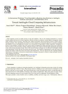
Figure 1: Connecting and Extending Models In Figure 1 shows the import relations between the models covered in this paper. We distinguish between two types of imports; a full import in which the full vocabulary of an ontology is imported in another ontology, and a selective import in which only specific concepts of an ontology are imported into the other. As can be seen, for the three infrastructure models (CDL, NOVI and GEYSERS) we fully import the vocabularies defined in NML and INDL. For EDL, only a few concepts from NML and INDL are imported (see Section 7.1) and the QOSAWF workflow ontology does not import any NML or INDL concepts at all. Instead, a separate mapping ontology is created 4
where concepts from NML, INDL and QOSAWF ontologies are aligned using owl:sameAs or owl:equivalentClass relations. Thus, using the different forms of imports and mappings, we allow (parts of) models to be easily re-used in other models. Additionally we see two more advantages of using OWL for describing computing infrastructures. First, the triples, the main data-format of OWL, form a semantic graph structure describing information about the elements. Such semantic graphs are a good match to computing infrastructures that can also be seen as large graphs of connected resources. Second, OWL provides explicit separation between semantics and syntax. An OWL Schema defines the ontology, i.e. the set of classes and the relations that can exist between those classes. Instances of these classes and their properties are then defined using an OWL syntax. One of the most popular syntaxes for OWL is XML/RDF which uses an XML notation to describe RDF triples, but other terser notations also exist. The clear separation of ontology and syntax also allow users to mix different ontologies without being hindered by the syntax in which these models are described.
4
Network Markup Language
In the past years network architectures, especially in research and educational networks, have seen a gradual shift in the type of services offered to end users and applications. They have moved from pure packetswitched data delivery services to a mixture of packet-switched and circuitswitched services. These hybrid networks [22] use optical and photonic devices to create circuits in a natural manner, e.g. DWDM devices. These circuits are nowadays an essential component in providing integrated networkcomputing services in cloud infrastructures. The extensive use of circuits in hybrid networks showed the need for interchangeable network models that could support the operation of control planes protocols, e.g. GMLPS. The Network Markup Language Working Group - NML-WG - within the Open Grid Forum has gathered together experts in the area of network topology descriptions and is working towards a first standard. The modeling effort done in NDL [1] has largely been incorporated in the NML schemas and expanded by adopting concepts and models from the PerfSONAR community [23]. Building on the experience of the different groups, the NML group has created a very generic network description schema [24]. This schema contains the necessary components to build a high-level domain network topology, but also go down to the technical details and describe all technological capabilities of a network. Figure 2 shows the basic elements of NML. Node is a machine part of the network, this can be a router, or just a regular PC. Port describes how a Node is connected to the network. 5
Ordered List ordered list of Network Objects
Bidirectional Link
Link Group
hasLink
2
isSink
isSource
group of Links rencoding: URI Link hasLabelGroup:Logical (virtual) directed data transport between Ports encoding: URI hasLabel:
Port Group
eri
isS
alC
pro
p om
ou
nd
ink videsL
Lin
k
Switching Service Ability to create a Link (cross connect) hasService
ha
sL
ink
Node A device, or partition of a device t r dPo t o u n n d Po r Inb has utbou hasNode O has
implementedBy
hasPort
group of Ports Port encoding: URI hasLabelGroup:Logical (virtual) directed Topology interface at a certain hasInboundPort connected graph hasTopology layer hasOutboundPort version: serial encoding: URI hasLabel: h pro asSer vide v sPo ice Deadaptation Service rt Ability to create a given deadaptation 2 Adaptation Service Ability to create a given Bidirectional Port adaptation
Figure 2: Network Markup Language main classes and properties.
Link is the connection between two Ports and Service defines the capabilities of a Node or Port, examples are a SwitchingService, or an AdaptationService respectively. An important difference with previous models is that NML is a completely unidirectional model. A single network port on a physical machine is modeled by two unidirectional NML Ports. Thus, a flexible model is created to describe uni- and bi-directional network concepts. One of the strengths of NML is that it provides natural support for distribution of information. Independent network operators can create topology descriptions for their infrastructure based on NML; they can publish them (on the Web) and control plane software can independently gather the information needed to create circuits across domains.
5
The Infrastructure and Network Description Language
The goal of the Infrastructure and Network Description Language (INDL) is to capture the concept of virtualization in computing infrastructures and to describe the storage and computing capabilities of the resources. The INDL ontology is built upon the NML ontology and it uses the nml:Node concept as the basic entity for describing a resource in a computing infrastructure. INDL can be used as a stand-alone model (i.e. without any network descrip6
tions), or it can be used in combination with NML by importing the NML ontology into the INDL definition. In the latter case, all NML concepts will become available to the user of INDL. implementedBy
rdfs:subClassOf nml:Node
VirtualNode
implements
Figure 3: INDL: Modeling virtualization of nodes. Virtualization is modeled using the VirtualNode concept, which is modeled as a subclass of nml:Node (i.e. virtual node inherits all properties of node). A virtual node is also implemented on a node (see Figure 3). The implementing node itself can be either a physical node or another virtual node. This allows us to create layers of virtualization stacked on top of each other. Storage Component rdfs:subClassOf
hasComponent Node Component
nml:Node partOf
size
rdfs:subClassOf
Double
Double Processor Component
speed cores
Integer
architecture String
rdfs:subClassOf Memory Component
size
Double
Figure 4: INDL: Modeling internal node components. Figure 4 shows how the internal components of a node are modeled by defining nml:Node to consist of a number of NodeComponent. The NodeComponent is an abstract class which describes the following essential components of machines which are of interest to the user: MemoryComponent shows how much memory is available at a node in GB, ProcessorComponent to describe how many cores a node has, their speed in GHz and architecture, and StorageComponent to define the space in GB available for local storage. The key feature of INDL which makes it reusable and easy to extend is that we have decoupled virtualization, functionality and connectivity. This allows us to add new functionality (e.g. adding a new type of NodeComponent) without impacting how we model its connectivity with other devices or how we model virtualization of the new resource. Furthermore, connectivity and functionality is modeled the same for physical nodes and virtual nodes which allows INDL to describe physical computing infrastructures as well as virtual 7
infrastructures.
6
INDL Extensions
To demonstrate the extensibility, applicability and flexibility of INDL, we will discuss a number of examples on how INDL has been used to meet the specific challenges imposed by its application to different computing infrastructures: the CineGrid infrastructure, the GEYSERS architecture and NOVI federation.
6.1
Cinegrid Description Language 4096
460800
2160
cdl:PixlesX cdl:PixlesY cdl:SAGEVisualize r nml:providesService nml:providesService
indl:hasComponent
2000
nml:isSink
ex:DAS4UvA nml:Node
indl:storageCapacity
nml:hasInboundPort
ex:CGEX_eth0 nml:Port
nml:providesService
2000
indl:hasComponent nml:hasOutboundPort cdl:DAS4UvA_storage indl:StorageComponent
ex:CGEX_to_Force 10 nml:Link
nml:hasOutboundPort
isSink
cdl:Jpeg2000_Intopix cdl:Codec cdl:TIFF cdl:Codec
ex:DAS4_eth0 nml:Port
ex:DAS4_to_Force10 nml:Link
nml:providesService nml:hasInboundPort ex:SwitchForce10 nml:SwitchingServ ice
ex:Force10_0/0 nml:Port
cdl:supportsCodec cdl:supportsCodec
isSource
ex:Force10 nml:Node
nml:isSource
cdl:supportsCodec cdl:TranscodeServ ice
nml:providesService
indl:hasComponent
ex:CGEX nml:Node
indl:storageCapacity
cdl:NFSStorage Service
cdl:DAS4UvA_compute indl:Processing Component
cdl:LocalStorage Service
cdl:CGEX_storage indl:Storage Component
cdl:Jpeg2000_NTT cdl:Jpeg2000
indl:CPUFrequeny
nml:providesLink
isSink
ex:Force10_0/1 nml:Port isSource
ex:SwitchLink nml:Link
Figure 5: CDL example CineGrid [25] is a multidisciplinary community that exploits the recent advances in computing, network infrastructures and adapts them to the digital cinema world. The CineGrid collaboration operates a distributed testbed spanning over multiple continents. The current nodes are located in the US, Europe, Asia and South America. All the sites are connected using high-speed dynamic photonic networks provided by the Global Lambda Integrated Facility community [26]. Each site operates a number of high capacity storage nodes while some sites also operate visualization and computing facilities that are able to access, display and process the stored content. These resources can be shared by the participants. The CineGrid Description Language [2]. is an ontology that covers all the types of services and devices along with their properties, specific to the 8
CineGrid infrastructure: storage services, video processing, streaming and transcoding services, screens, projectors, tiled displays, etc. In CineGrid exchangeable service and infrastructure descriptions for the supporting devices are the basis to run applications across multiple domains. An earlier version of CDL defined concepts for CineGrid nodes (collections of elements under a single administration), hosts (compute resources that provide various services) and clusters (collections of hosts). Using the owl:sameAs property a connection was made to similar concepts in NDL. To facilitate a better integration between NML and CDL we have adjusted CDL such that it directly imports concepts from INDL and NML. Thus CDL Node has been replaced by NML Topology, CDL Cluster is replaced by NML Group and CDL Host is replaced by NML Node. In addition to compute resources CDL also provides concepts for high resolution displays, i.e. Display and Projector. As mentioned above, CDL provides concepts for the various services encountered in the CineGrid ecosystem: Storage, Visualizer, Transcoder, Streamer. Each concept is further subclassed and extended with properties to accommodate a specific technology. For example a Transcoder service can support only a limited range of codecs. This is expressed through the supportsCodec relation. Codecs are also expressed as concepts that inherit the base class Codec. Figure 5 describes a small part of the infrastructure available in the CineGrid test bed. It shows one of the CineGrid Amsterdam Exchange storage nodes connected to one of the sites of the DAS4 distributed cluster. These two resources can be used for the storage, streaming and processing ( compression, decompression, image transformation) of ultra high quality media that is typically used in digital cinema. The CGEX node provides two services: storage and visualization (sink of a video stream). The compute cluster also provides two types of services: storage and processing. In order to efficiently represent the capabilities of the compute cluster, it’s nodes compute and storage resources are represented as two aggregated values. The cluster provides also a transcoding service that can encode and decode to and from three different types of image formats widely used for high resolution video.
6.2
The NOVI Information Model
NOVI (Networking innovations Over Virtualized Infrastructures) [4] researches methods, algorithms and information systems that can enable composition and management of isolated (virtual) resources provided by different federated Future Internet (FI) platforms. The NOVI Information Model provides abstractions and semantics of federated virtualized resources, enabling ontology-based tools and algorithms used by all the various services operating in the architecture. The information model developed in NOVI has two 9
ex:TopLifetime nml:Lifetime ex:FEDERICA novi:Platform
nml:startTime
21 April 2012, 11:00:00 CEST
nml:existsDuring
ex:PlanetLab novi:Platform
ex:RequestA nml:Topology
novi:isContainedIn nml:hasNode ex:NodeA indl:VitualNode
novi:isContainedIn
nml:hasNode
ex:NodeB indl:VirtualNode
ex:NodeA_to_NodeB nml:Link
nml:hasOutboundPort nml:hasService nml:isSource nml:hasInboundPort ex:Storage ex:NodeA_out novi:StorageService nml:Port
nml:hasInboundPort
nml:locatedAt nml:hasOutboundPort ex:NodeB_in ex:Amsterdam nml:Port nml:Location
nml:isSink
ex:NodeB_out nml:Port
ex:NodeA_in nml:Port novi:hasStorageSize 50 GB
19 April 2012, 11:00:00 CEST
nml:endTime
nml:isSource
nml:isSink ex:NodeB_to_NodeA nml:Link
Figure 6: Example request showing two nodes on federated platforms in NOVI main objectives. First, to model abstractions supporting the federation of the FEDERICA and PlanetLab Europe platforms, and second to define the necessary modeling concepts needed by other Future Internet platforms to join the NOVI innovation cloud at a later stage. The federation of different platforms goes further than just providing access to resources. Several services from the different platforms have to be combined. An example is authentication and policy, so that the user can log in directly to the NOVI layer and use resources that he is entitled to. Another example is a federated monitoring service so as to provide a user with a single access point for monitoring his virtual infrastructure. Both the requesting and the monitoring services require an information model describing resources from the different platforms. In NOVI we use a general ontology based on INDL to describe resources and infrastructure. Figure 7 shows the classes that are currently defined in the NOVI Information Model (IM). • Platform is introduced as a subclass of the NML Group and it describes a particular platform in the NOVI federation. Resources can be linked to the class to denote membership of that platform, and it can provide pointers to other information such as the management service of that platform. • the NML Service concept is extended with four additional subclasses to describe the services which can be implemented by the NOVI resources. For example requesting a total of X GB of storage. We have different services to describe CPU Processing power, Memory size, Storage size, and network Switching capabilities. Figure 6 shows a possible request for NOVI. The request contains a very 10
nml:Service
rdfs:subClassOf Processing Service
rdfs:subClassOf rdfs:subClassOf rdfs:subClassOf
Memory Service
Storage Service
nml:Group
nml:Node isContainedIn
Switching Service
rdfs:subClassOf Platform
Figure 7: The classes defined in the NOVI resource ontology simple topology with two nodes that are connected to each other, starting April 19th 2012 at 11:00:00 CEST and lasts 48 hours from that time. An added constraint here is that the nodes must be on different platforms, in this case PlanetLab and FEDERICA respectively. Furthermore, the node in PlanetLab is requested to be in Amsterdam, and the node in FEDERICA should have a storage service of at least 50 GB. This request can of course be extended with more resources, nodes in other platforms, et cetera.
6.3
The GEYSERS Information Modeling Framework
The information model that was developed in the GEYSERS EU-FP7 project [3] focusses on one specific component in the GEYSERS architecture, the Logical Infrastructure Composition Layer (LICL) [27]. The LICL uses virtualization to decouple the physical infrastructure from its associated controlplane and enables on-demand provisioning of virtual infrastructures. A key aspect of the LICL is that it enables composing resources that belong to different infrastructure providers. This aspect was a main motivation for adopting the semantic approach also in this project. The LICL information modeling framework enables the different LICL components – possibly residing at different infrastructure providers – to interact using a common vocabulary. The initial required ingredients for this information model are: physical resources (IT and network resources), virtual infrastructures and virtual infrastructure requests, energy related aspects, quality of service, and security aspects. The GEYSERS information model imports the INDL ontology including all network related concepts from NML. 6.3.1
Modeling Optical Switches
One of the requirements for the GEYSERS information model is to describe optical switches. Because INDL nor NML contain any concepts specifically for describing optical switches, the INDL NodeComponent is extended with 11
a new subclass OpticalSwitchComponent as shown in Figure 8. A more elaborate description of these concepts and their properties can be found in [28]. indl:Node Component
Range outputPower inputPower
rdfs:subClassOf FiberType
fiberType OpticalSwitch Component
insertionLoss double
returnLoss rdfs:subClassOf
configurationTime
rdfs:subClassOf Duration ROADM Component
OXC Component
addWavelengths
wavelengthsPerFiber
dropWavelengths
numberOfWavelengths
bypassWavelengths integer
Figure 8: Concepts for modeling Optical Switches in the GEYSERS Information Modeling Framework. The OpticalSwitchComponent has the following properties: • inputPower and outputPower describe the input and output range of the power that an optical switch is able to handle and provide. • fiberType describes whether the type of fiber supported by the optical switch is single-mode or multi-mode. • insertionLoss and returnLoss describe the optical loss in power of the optical switch. • configurationTime is the time needed to configure the switch by adding or removing internal switchedTo links between the Interfaces. • impairment describes the linear and nonlinear effects such as polarizationdependent loss (PDL), polarization-mode dispersion (PMD), chromatic dispersion, crosstalk, etc. To model a ROADM and OXC, specific components for these types of devices have been added as subclasses of OpticalSwitchComponent. • addWavelengths describes the number of wavelengths added by a ROADM. • dropWavelengths describes the number of wavelengths dropped by a ROADM.
12
• bypassWavelengths describes the number of wavelengths that are bypassed by a ROADM. • wavelengthsPerFiber to describe the number of wavelengths an OXC is able to put on a single fiber. • numberOfFibers the total amount of (input plus output) fibers an OXC has. 6.3.2
Modeling Virtualization
The GEYSERS LICL acts as a middleware for the decoupling of the physical substrate and the provisioning of a virtual infrastructure as a service. In order to accomplish this, a complex layer of virtualization needs to be modeled in which we need to distinguish between different types of virtual nodes. Therefore, the INDL VirtualNode concept has been extended with three new subclasses as shown in Figure 9. indl:Virtual Node rdfs:subClassOf rdfs:subClassOf Logical Resource
rdfs:subClassOf ResourcePool
Virtual Resource
Figure 9: GEYSERS Extension of the VirtualNode concept. • LogicalResource represents the aggregation of a number of physical IT resources (i.e. Nodes) into a single resource. Systems like OpenNebula or OpenStack can be used to manage such a cluster of IT nodes and offer its capacity to the upper layer in the LICL system. The LogicalResource also describes the hypervisor that is being used. • ResourcePool is used to indicate a reservation of (part of) a LogicalResources capacity for future use. • VirtualResource represents an instantiated virtual machine or virtual switch. A VirtualResource can support different types of diskimages and also point to a URI where the VM image is located. Figure 10 gives a simplified example on how these three concepts are used to represent a virtual infrastructure that is embedded on the physical substrate. It shows two storage nodes and two compute nodes that are both aggregated into a LogicalResource. For the sake of the example, the OXC resource is partitioned into two virtual OXCs, both represented as a VirtualResource. On both of the logical resources, a ResourcePool 13
ex:VM1 gey:Virtual Resource
ex:StoragePool gey:ResourcePool
ex:VirtualOXC2, gey:Virtual Resource
ex:VirtualOXC1 gey:Virtual Resource
indl:implements indl:implements
indl:implements indl:implements
ex:LR1, gey:Logical Resource
ex:LR2, gey:Logical Resource
ex:ComputePool gey:ResourcePool
ex:VM2 gey:ResourcePool
indl:implementsindl:implements ex: OXCComp gey:OXC Component
ex:LR3 gey:Logical Resource
indl:implements indl:implements indl:implements ex:Storage1 nml:Node
indl:hasComponent
ex:Storage2 nml:Node
indl:implementsindl:implements
ex:OXC1 nml:Node
ex:Compute1 nml:Node
nml:hasInboundPort nml:hasOutboundPort nml:providesService
nml:hasOutboundPort
ex:Storage1out nml:Port
ex:OXCin nml:Port
nml:isSource
nml:isSink
ex:Storage1_to_OXC nml:Link
nml:isSource
nml:providesLink
nml:hasInboundPort
ex:OXCout nml:Port
ex:OXCSwitchService nml:SwitchingService nml:isSink
ex:OXC_switch nml:Link
ex:Compute2 nml:Node
nml:isSource
ex:Compute1in nml:Port nml:isSink
ex:OXC_to_Comput1 nml:Link
Figure 10: GEYSERS Virtualization Model. is implemented to reserve some capacity for future use. Two VMs, each represented as VirtualResource, are also instantiated and connected via the two virtual OXCs. The example also shows how the NML concepts are used to define a unidirectional connection from one of the storage nodes via the OXC to one of the computing nodes.
7
INDL usage
In the previous section we have shown how NML and INDL are used to define the models for three different computing infrastructures. In this section we show how NML and INDL is used by the Energy Description Language (EDL). EDL is a model aimed at monitoring energy related aspects of computing infrastructures. By connecting EDL to NML and INDL, it can be easily used for monitoring the previously discussed computing infrastructures. Another usage of NML and INDL is its application for modeling workflows on large scale computing infrastructures. In this case, a quality of service and workflow ontology (QOSAWF) is defined that is completely separate from NML and INDL. Instead of importing NML or INDL concepts, a separate mapping ontology defines the relations between the QOSAWF ontology and the NML and INDL ontologies.
7.1
EDL - Energy Description Language
The total energy consumption, the energy sources used and pragmatically the cost of power are becoming increasingly important factor in the planning, design and operation of ICT infrastructures. The use of virtualization and
14
the possibility to rely onto IaaS offerings provide new dimension when trying to manage power and increase greenness of an infrastructure. The Energy Description Language (EDL) [29] is an OWL ontology that describes all the energy related parameters that are needed for power management in such large scale (virtual) infrastructures. EDL supports several power management scenarios; among others for example in green path searches, where only resources powered by green energy sources can be used; low-power resource selection, where resources with low power characteristics, e.g. solid state disks, low-power processors, are preferred; peak power management, where it is important to track the maximum power the resource consumes to judge whether this is above a predefined upper bound. Figure 11 shows the classes and the main properties of this ontology.
nml:Network Object
edl:EnergyEff icientEthernet
indl:Node Component
edl:Embedde dProcessor
isa
edl:Resource
edl: describedBy
edl:Resource EnergyDesc
edl:monitorBy
isa
edl:Software Component
edl:Energy Metric
edl:hasOutlet isa edl:informOf edl:Observed edl:Outlet Metric
edl: PowerAvg
Active
isa
isa
edl:PowerMet er
edl: PowerCapping
Sleep
isa
edl:Metric
isa
isa
edl: GreenEnergy
Off
edl:sampleAt
edl:hasUnit
edl:Hardware Component
edl: BrownEnergy
isa
edl:Datetime
edl:Unit isa
edl:SolidState Disk
edl: EnergySource edl: PowerState
edl: Capability
edl:Monitor Component isa
isa
isa
edl: PowerFeature
qosawf: QualityMetric isa
isa
qoasw: Throughput proportionalTo
edl:Calculate dMetric
inisa proportionalTo edl: edl:Energy ActiveEnergy Efficiency
isa
isa
isa
edl:Power Efficiency
Figure 11: The Energy Description Language - EDL and its three main parts: the EnergyMetric class and subclasses (in yellow), the Monitor Component class and its subclasses (in orange) and the ResourceEnergyDescription and it subclasses (in gray) The figure shows the relation between NML, INDL and EDL: at the top left of the figure we can see a nml:NetworkObject and an indl:NodeComponent belong to an edl:Resource, which is monitoredBy an edl:MonitorComponent and has a corresponding edl:ResourceEnergyDescr. All NML and INDL resources can be monitored for their power consumption and their energy characteristics can be described accurately so that power management systems can use all this extra additional data.
15
7.2
Planning workflow over large scale infrastructure
Data intensive applications, such as collaborative digital media processing [30], have very high requirements for the underlying services and the network connections, and the resources are often provided by different domains. Reserving resources from the infrastructure is a way to create a dedicated environment for executing workflows with very high performance requirements. The logic of workflow applications can be modelled from different abstractions; from high level description to underlying concrete services that require mapping between different abstractions. Fig. 12 roughly shows the mapping between workflow process descriptions to the underlying network that connects devices for hosting services and data for supporting the processes. Application logic
Data types
Service types
Services
Devices (Physical/Virtualized)
Network connectivity
Figure 12: The Network Service Interface and resource selection in workflow applications. Developing optimal searching strategies that can efficiently search and reserve network resources to connect the computing and storage services required by the workflow is the core problem. The INDL provides a suitable mechanism to describe the resources in the computing and storage infrastructure, and network connectivity among those resources. NEtWork QoS Planner (NEWQoSPlanner) is a workflow planning system which is able to select network resources in the context of workflow composition and scheduling [31]. In the NEWQoSPlanner system, a schema for describing abstract
16
workflows process(qosawf.owl ) was proposed to define the basic concepts of workflow processes, pre/post/execution conditions of a process, data, and quality attributes, as shown in Fig 13.
Figure 13: The concepts defined in the qosawf schema. The original application context of NEWQoSPlanner is CineGrid, and the mapping mechanism between the qosawf.owl and the CineGrid is via a separate file called qosawf-ontmap-cdl.owl [31]. The information model of INDL promotes a better mapping between services, storage and computing elements, and the network topologies compared to the early semantic description stack used by the NEWQoSPlanner.
8
Conclusions
An interesting comparison can be made between INDL and the NDL-OWL model. NDL-OWL extended NDL and chose the Web Ontology Language (OWL) instead of RDF. Their ontology models networks topology, layers, utilities and technologies (PC, Ethernet, DTN, fiber switch) and it is based on NDL. This is also the main difference between NDL-OWL and INDL. The approach for modeling network topologies in NDL-OWL is based on NDL while INDL uses the latest developments in the OGF NML-WG. Furthermore, NDL-OWL covers cloud computing, and in particular software and virtual machine, substrate measurement capabilities and service procedures and protocols. In this respect it is a necessary next step to try to align INDL and NDL-OWL as much as possible, and we see this as an opportunity to be pursue within a standardization working group. 17
In this paper we have shown how we define the Infrastructure and Description Language (INDL) as an extension of Network Markup Language (NML), thus creating a extensible, technology independent model of a computing infrastructure. The extensibility and applicability is demonstrated by using INDL as a basis for modeling three different infrastructure: the CineGrid infrastructure, the NOVI federated platforms and the GEYSERS architecture. The use of Semantic-Web technology in our approach facilitates the creation of models that can be easily connected, stacked and extended by other models. The focus of this paper is mainly on modeling computing infrastructures. However for future work we foresee a complete modeling suite, including infrastructure descriptions, monitoring models and access policy models. The use of the Energy Description Language (EDL) as a monitoring ontology can be seen as a first step in this direction.
Acknowledgments This work was partially supported by the European Commission, 7th Framework Programme for Research and Technological Development, Capacities, Grant No. 257867 – NOVI and Grant No. -248657 - GEYSERS. Furthermore, this publication was supported by the Dutch national program COMMIT and the GigaPort 2012 Research on Networks project.
References [1] J. J. van der Ham, F. Dijkstra, F. Travostino, H. M. A. Andree, C. T. A. M. de Laat, Using RDF to describe networks, Future Generation Computer Systems - IGrid 2005: The global lambda integrated facility 22 (8) (2006) 862–867. [2] R. Koning, P. Grosso, C. T. A. M. de Laat, Using ontologies for resource description in the CineGrid Exchange, Future Generation Computer Systems 27 (7) (2011) 960–965. [3] E. Escalona, S. Peng, R. Nejabati, D. Simeonidou, J. A. Garcia-Espin, J. Ferrer Riera, S. Figuerola, Y. Demchenko, C. de Laat, E. Al., GEYSERS : A Novel Architecture for Virtualization and Co-Provisioning of Dynamic Optical Networks and IT Services, in: Proceedings Future Network and Mobile Summit, 2011. [4] NOVI - Networking innovations Over Virtualized Infrastructures. URL http://www.fp7-novi.eu/ [5] Y. Demchenko, J. J. van der Ham, M. Ghijsen, M. Cristea, V. Yakovenko, C. T. A. M. de Laat, On-Demand Provisioning of Cloud 18
and Grid based Infrastructure Services for Collaborative Projects and Groups, in: The 2011 International Conference on Collaboration Technologies and Systems (CTS 2011), 2011. [6] T. Berners-Lee, J. Hendler, O. Lassila, The Semantic Web, Scientific American (2001) 29–37. [7] M. Ghijsen, J. van der Ham, P. Grosso, C. T. A. M. de Laat, Towards an Infrastructure Description Language for Modeling Computing Infrastructures, in: Parallel and Distributed Processing with Applications (ISPA), 2012 IEEE 10th International Symposium on, IEEE, 2012, pp. 207–214. [8] Open Cloud Computing Interface (OCCI). URL http://occi-wg.org/ [9] Common Information Model (CIM). URL http://dmtf.org/standards/cim [10] Distributed Management Task Force (DMTF). URL http://www.dmtf.org/ [11] J. Strassner, DEN-ng: achieving business-driven network management, in: Network Operations and Management Symposium, 2002. NOMS 2002. 2002 IEEE/IFIP, 2002, pp. 753–766. [12] G. P. Koslovski, P. V.-B. Primet, A. S. Char˜ao, P. Vicat-Blanc Primet, A. Schwertner Char˜ ao, VXDL: Virtual Resources and Interconnection Networks Description Language, in: Networks for Grid Applications, Vol. 2 of Lecture Notes of the Institute for Computer Sciences, Social Informatics and Telecommunications Engineering, Springer Berlin Heidelberg, 2009, pp. 138–154. [13] Lyatiss Resources. URL http://www.lyatiss.com/resources/ [14] C. E. Abosi, R. Nejabati, D. Simeonidou, Design and Development of a Semantic Information Modelling Framework for a Service Oriented Optical Internet, Journal of Networks 5 (11) (2010) 1300–1309. doi:10.4304/jnw.5.11.1300-1309. [15] O.-D. Ntofon, D. K. Hunter, D. Simeonidou, Towards semantic modeling framework for future service oriented Networked Media Infrastructures, 2012 4th Computer Science and Electronic Engineering Conference (CEEC) (2012) 200–205doi:10.1109/CEEC.2012.6375405. [16] GENI Project. URL http://www.geni.net/ 19
[17] B. Chun, D. Culler, T. Roscoe, A. Bavier, L. Peterson, M. Wawrzoniak, M. Bowman, PlanetLab: an overlay testbed for broad-coverage services, SIGCOMM Comput. Commun. Rev. 33 (3) (2003) 3–12. [18] ProtoGENI RSpec. URL http://www.protogeni.net/trac/protogeni/wiki/RSpec [19] Slice Federation Architecture (SFA). URL http://groups.geni.net/geni/attachment/wiki/ SliceFedArch [20] I. Baldine, Y. Xin, A. Mandal, C. Heermann, J. Chase, V. Marupadi, A. Yumerefendi, D. Irwin, Networked cloud orchestration: A geni perspective, in: Workshop on Management of Emerging Networks and Services, 2010. [21] Web Ontology Language (OWL). URL http://www.w3.org/2004/OWL/ [22] C. T. A. M. de Laat, E. Radius, S. Wallace, The Rationale of the Current Optical Networking Initiatives, Future Generation Computer Systems 19 (6). [23] A. Hanemann, J. W. Boote, E. L. Boyd, J. Durand, L. Kudarimoti, R. Lapacz, D. M. Swany, S. Trocha, J. Zurawski, PerfSONAR: A Service Oriented Architecture for Multi-domain Network Monitoring, in: B. Benatallah, F. Casati, P. Traverso (Eds.), Service-Oriented Computing - ICSOC 2005, Vol. 3826 of Lecture Notes in Computer Science, Springer Berlin / Heidelberg, 2005, pp. 241–254. [24] Network-Markup Language Schema Diagram. URL https://forge.ogf.org/sf/go/doc15481 [25] P. Grosso, L. Herr, N. Ohta, P. Hearty, C. T. A. M. de Laat, Editorial: CineGrid: Super high definition media over optical networks, Future Generation Computer Systems 27 (7) (2011) 881–885. [26] Global Lambda Integrated Facility (GLIF). URL http://www.glif.is [27] J. A. Garcia-Espin, J. Ferrer Riera, S. Figuerola, M. Ghijsen, Y. Demchenko, J. Buysse, M. de Leenheer, C. Develder, F. Anhalt, S. Soudan, Logical Infrastructure Composition Layer, the GEYSERS Holistic Approach for Infrastructure Virtualisation, in: Networking to Services, The 28th Trans European Research and Education Networking Conference, 21-24 May, 2012, Keykjavik, Iceland, Selected Papers, 2012.
20
[28] R. Nejabati, E. Escalona, S. Peng, D. Simeonidou, Optical Network Virtualization, in: Optical Network Design and Modeling (ONDM), 2011 15th International Conference on, 2011, pp. 1–5. [29] H. Zhu, K. van der Veldt, P. Grosso, Z. Zhao, X. Liao, C. de Laat, Energy-aware semantic modeling in large scale infrastructures, in: The IEEE International Conference on Green Computing and Communications, GreenCom 2012, 2012. [30] G. Fortino, C. E. Palau (Eds.), Next generation content delivery infrastructures: emerging paradigms and technologies, IGI, 2012. [31] Z. Zhao, P. Grosso, J. van der Ham, R. Koning, C. de Laat, An agent based network resource planner for workflow applications, International Journal of Multiagent and Grid Systems 7/6 (2011) 187–202.
21