model in an integrated way: class, state and structure diagrams. We propose and prove a decomposition law for active classes, as an illustration of a sound.
A Semantics for UML-RT Active Classes via Mapping into Circus Rodrigo Ramos, Augusto Sampaio and Alexandre Mota Informatics Center, Federal University of Pernambuco P.O.Box 7851 - 50.740-540, Recife-PE, Brazil {rtr,acas,acm}@cin.ufpe.br
Abstract. The lack of a formal semantics for UML-RT makes it inadequate for rigourous system development, especially if the preservation of behaviour is a major concern when applying well-known model transformations, like refactorings and refinements. In this paper, we propose a semantics for UML-RT active classes through a mapping into Circus, a specification language that combines CSP, Z and specification statements. As a consequence of the translation, we are able to prove that model transformations preserve both static and dynamic behaviour, using refinement laws and a relational semantics of Circus, based on the Unifying Theories of Programming. Keywords: UML-RT, Circus, method integration, model transformations
1
Introduction
As other object-oriented (OO) methods, UML [1] has tremendously influenced the software engineering modeling practice with rich structuring mechanisms. Despite its strengths, the rigorous development of non-trivial applications does not seem feasible without a formal semantics. The reason is that well-known model transformations might not preserve behaviour. This problem is even more serious in a model driven development, where transformations are as important as models, and involve different model views. In the literature, several efforts address the problem through the integration of UML models with formal languages; there are some approaches to specification [2,3], like combinations of UML with Z [4] or with CSP [5]. A formalisation of class diagrams using the state-based Z notation is presented in [2]; a detailed comparison of general integration approaches involving Z and Object-oriented extensions of Z is discussed in [6]. Concerning formal semantics of state diagrams, a mapping into CSP processes is presented in [3]; typically, each contribution to formalise UML tends to concentrate on a single view (like state or class diagrams). Although some works like, for instance, [7], use a uniform notation to describe a mapping that considers both structure and behaviour, the presentation is informal, based on examples. Similar limitations can be found in works [8,9] that formalise UML-RT [10] (a conservative UML profile that includes active objects to describe concurrent
and distributed applications) using CSP. They focus on the translation of the UML-RT structural view into CSP [8], and consider the behavioural representation of active objects [9] only partially. For example, statecharts of capules and protocols, and their relationship with the structure diagrams are not addressed. Also, model transformations are usually neglected or, when considered, the presentation is informal [11] and does not encompass all the model views. In this paper, we propose a semantics for UML-RT via mapping into Circus [12], a language that combines CSP, Z and specification statements. We focus on mapping the new elements (active classes and other related constructs) that UML-RT adds to UML. We consider the following views of a UML-RT model in an integrated way: class, state and structure diagrams. We propose and prove a decomposition law for active classes, as an illustration of a sound model transformation; the law and its proof consider the views mentioned above. One reason for using Circus is that its semantics is defined in the setting of the Unifying Theories of Programming [13]; this relational model has proved convenient for reasoning. Another advantage is that Circus includes the main design concepts of UML-RT. Unlike, for instance, CSP-OZ [14], Circus decouples event occurrences from state operations (like in UML-RT), and it has been designed to support a refinement calculus [15]; the decoupling seems crucial for addressing refinement. The laws of Circus have been inspiring both to propose laws for UML-RT ([16]) and to prove such laws as illustrated in this paper. The next section gives an overview of UML-RT, and Section 3 introduces Circus. Section 4 presents a mapping from UML-RT into Circus. Soundness of model transformations is addressed in Section 5, where we propose and prove a transformation law. Finally, we summarise our results and topics for future work in Section 6.
2
UML-RT
The specification and design of a distributed system is a complex task involving data, behaviour, intercommunication and architectural aspects of the model. In order to fulfill these requirements, UML and ROOM (Real-Time ObjectOriented Modeling language) have been combined into UML for Real-Time (UML-RT) [10]. Some of the ROOM techniques also motivated extensions in the UML 2.0 [17] version. Here we use UML-RT because we consider that the proposed model for active objects is more consolidated than that proposed for UML 2.0. Furthermore, UML-RT counts with commercial tool support. Using stereotype mechanisms, UML-RT introduces four new constructors: capsule, protocol, port and connector. Capsules (active classes) describe, potentially concurrent, architectural components that may interact with their environment only through signal-based objects called ports. Ports realise protocols, which define a set of signals that a capsule can receive or send. A protocol also defines the valid flow of information (signals) between connected ports of capsules. Connectors act as a physical communication channel between ports.
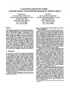
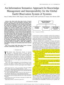
Fig. 1. Class, Structure and State Diagrams of a Manufacturing System A UML-RT model of the system is formed of a set of diagrams and system properties. We choose diagrams that mainly represent the following architectural views: static data, dynamic behaviour, and dynamic object relationships; these are expressed, respectively, by class, state and structure diagrams. We directly express the system properties by invariants, pre- and post-conditions in Circus; they could alternatively be expressed in OCL [18], but an OCL to Circus mapping is out of the scope of this work. In order to illustrate the notation, an example of a simplified manufacturing system is used. In Figure 1 (top left rectangle) a class diagram is presented. Capsules and protocols are graphically represented in the diagram by a box with a stereotype Capsule and Protocol, respectively; a symbol at the top right is also used to characterise their representations. The diagram emphasises the relationships between the ProdSys and Storage capsules. The capsule Storage is a bounded, reactive, FIFO buffer that is used to store objects of class Piece, and ProdSys is used to process these objects. These capsules have an association to the protocols, which are used to govern the communication among capsules. The protocol STO declares the input signal req (used to communicate the request of a work piece) and the output signal output (which communicates the delivery of a work piece). The protocol STI declares a signal input to store a piece. By their own nature, capsules provide a high degree of information hiding. As the communication mechanism is via message passing, all capsule elements are hidden, including not only attributes, but also methods. The capsule Storage has a set of Pieces, represented by the association buffer, and methods to threat this set. The only visible elements in the capsule are ports, which can be connected to other capsule ports to establish communication; here, we assume that this communication is synchronous. This decoupling makes capsules highly reusable. In addition, a capsule can also be defined hierarchically, in terms of subcapsules, each with a state-machine and possibly a hierarchy of compound capsules.
A structure diagram, a kind of collaboration diagram, describes a capsule structural decomposition, showing the capsule interaction through connections among its ports and permitting hierarchically composed models. The structural decomposition of ProdSys is shown in Figure 1 (top right rectangle). It is composed by the capsule instances sin and son of Storage, which also communicate with ports of ProdSys; these capsule instances are created as a consequence of the association of ProdSys with the capsule Storage in the class diagram. Block filled squares in the capsule instances represent their ports, where white ones are conjugated (their signal directions are inverted in relation to the ordinary ports). Ports are basically divided into two types: relay ports and end ports. End ports are used by the capsule statechart to receive or transmit signals, while relay ports are used to connect other ports (like protected ports of the capsule or public ports of subcapsules) in the capsule internal structure diagram to the external environment. In the structure diagram of ProdSys, the ports pi and po are protected end ports used only by its statechart, while mi and mo are public relay ports used only to connect ports of subcapsules to the environment. In Storage, si and so are public end ports. The capsule behaviour is described in terms of UML-RT statecharts, which extend the ROOMCharts concept [19] and differ from the standard UML statecharts [1] including some adaptations to better describe active objects (for instance, UML-RT statechart do not have final states). A statechart is composed by transitions and states; in general, a transition has the form p.e[g]/a, where e is an input signal, p is the port through which the signal arrives, g is a guard and a is an action. Input signals and a true guard trigger the transition. As a result, the corresponding action is executed. We assume that events, guards and actions are expressed using the Circus notation. For example, in the statechart of Storage, there are two transitions from state Sa. The one on the right triggers if the req signal arrives through port so and the buffer is non-empty. The corresponding action declares a variable x to capture return of the method remove. This is the way it is done in Circus, since remove is actually interpreted as a Z-Schema, as explained in the next section. The value of x is then through channel so. The syntax for writing these actions related to communication are also as in Circus. In this work we do not consider capsule inheritance, mainly because its semantics in UML-RT is not yet welldefined; according to the ROOMCharts definitions [19], inherited capsule is able to arbitrarily change the behaviour defined in its super capsule. In UML-RT, states are classified as initial, choice, composite or simple. Initial states are transient states that mark the starting point of a state-machine. A composite state groups other states, whereas a simple one has no other state inside. Choice states are those that involve a decision of which path to take according to its guard; there exist only two outgoing transitions: one is triggered when the guard is true; otherwise the second is triggered. Composite states are divided into two types: Or-States and And-States. An Or-State defines that only one of its substates is active, whereas And-States contain regions that are
executed in parallel, and permit each region to have an active state per time. Further details about composite states are presented in Section 4.2. For a capsule state-machine, we assume that there is a composite state that contains all other states; it is called the top state (S0 ) and is implicitly reached when the capsule instance is created. Figure 1 (bottom) presents the statecharts of ProdSys, Storage, STO and STI. Their respective top states (S0 ) are Or-States that sequentially execute the inner states. In Storage, for example, the initial state moves to the state Sa. Next it waits the arrival of the input or req signals. The behaviour of Storage is further explained in the next section.
3
Circus
The language Circus [12] includes the notion of a process, whose state is defined using a Z schema and behaviour by an action expressed in the CSP notation. Process interaction is defined via channels to communicate values or just synchronise events. Therefore, the specification of a Circus program is defined by a sequence of paragraphs, which can include: Z paragraphs, process definitions, and channel declarations. As a simple example, consider the capsule Storate of Figure 1. It can be specified in Circus as the following process. |N :N TSTI ::= input � Piece � channel si : TSTI TSTO ::= req | output � Piece � channel so : TSTO process Storage = b begin state StorageState = b [buff : seq Piece; size : 0..N | size = #buff ≤ N ] initial StorageInit = b [StorageState 0 | buff 0 = hi ∧ size0 = 0] insert = b [∆StorageState; x ? : Piece | size < N ∧ buff 0 = buff a hx ?i ∧ size0 = size + 1] remove = b [∆StorageState; x ! : Piece | size > 0 ∧ x ! = head buff ∧ buff 0 = tail buff ∧ size0 = size − 1] Sa = b (size < N & si?input.x → insert; Sa) 2 (size > 0 & so.req → (var x : Piece • remove; so!output.x); Sa) • StorageInit; Sa end
The maximum size of this buffer is a strictly positive constant N . The buffer program takes its inputs and supplies its outputs through the channels si and so, respectively. The free types TSTI and TSTO categorise the values communicated by these channels. In TSTO , req and output are constructors of the free type, used to communicate the request and delivery of objects, respectively. Similarly, in TSTI , input is used to represent the storage of objects of type Piece. In Circus the body of a declaration of a process is delimited by the begin and end keywords; it is composed by a sequence of paragraphs and a main action (after the • symbol), which defines the process behaviour. One of these paragraphs is used to describe the state of the process (identified by the keyword state), which encapsulates its data components. Furthermore, the other
paragraphs describe process operations and actions, that are used to structure the process specification and the main action. In our example, the process Storage encapsulates two state components in the Z schema StorageState: an ordered list buff of contents and the size of this list, represented by size. Initially, the buff is empty and, therefore, its size is zero; this is specified as a state initialisation action StorageInit. The main action initialises the buffer and repeatedly offers the choice of input and req. The signal input is guarded by size < N . The process accepts an input whenever there is space to store the new value; in this case, the piece is appended to the bounded sequence and the size incremented. The effect on the state is described by a schema as usual, using the operator insert. The action si?input.x → put is a prefixing in the style of CSP. A new input variable x is introduced, and a value input through the channel si is assigned to it. Afterwards, the action insert is executed. The req signal is enabled providing that the buffer contains something (size > 0). Afterwards, the Buffer offers output to deliver a piece. The associated state modification is defined by the remove schema action, which removes the head of buffer and updates the size accordingly. The example has shown how processes are constructed from actions, but processes may themselves be combined with CSP operators, such as parallel composition (A1 |[ cs ]| A2 ). The meaning of a new process constructed in this way is obtained from the conjunction of the constituent states of the processes in composition (A1 and A2 ) and the parallel combination of their main actions, synchronising on the set of channels (cs). At the level of actions, the Circus parallel operator is actually slightly different from that of CSP. To resolve conflicts in the access to the variables in scope, it requires a synchronisation set and two sets that partition those variables. In the parallelism A1 |[ ns1 | cs | ns2 ]| A2 , the actions A1 and A2 synchronise on the channels in set cs. Although both A1 and A2 have access to all variables, they can only modify the values of the variables in ns1 and ns2 , respectively. Further explanation of the Circus notation used in this work is introduced as the need arises, in the next section. A more detailed presentation of Circus, including its complete grammar and formal semantics, can be found in [20].
4
Semantic Mapping
This section gives meaning to UML-RT elements through a mapping into Circus. This translation provides a mapping of structural and behaviour UML-RT elements into Circus. In our approach, UML-RT classifiers with an associated behaviour (capsules and protocols) are mapped into processes, and ports into channels. The mapping of classes has been addressed by several authors, and is out of the scope of our work. For example, in [2] classes are mapped directly into Z paragraphs. In this sense, our work complements those approaches. In our strategy the target of the translation is a Circus specification that is itself the meaning of the original model. Concerning the structure diagrams,
we consider that they implicitly define an extensional view of the system; they contain the set of capsule instances. To deal with hierarchical structures, we assume that all capsule instances, ports and connections have distinct names. When mapping elements declared as a list (such as attributes and methods of a capsule, or signals of a protocol), by convention we single out one of its elements, present its mapping , and invoke a meta function (TL()) to translate the remaining elements. We assume that there are overloaded definitions of TL() for each kind of list. In practice such lists can obviously be empty, but we avoid this trivial case assuming that they have at least one element. 4.1
UML-RT Structural Elements
A protocol declaration in UML-RT encapsulates both the communication elements and the behaviour. In Circus, this gives rise to two major elements: a stateless process that captures this behaviour and a channel to represent the communication elements. Regarding the signals, a possible mapping would be to introduce a channel associated with each signal. Rather, we use a single channel to communicate all signals of a protocol. This channel communicates values of a free type, with each constructor representing a signal. Using a single channel facilitates the mapping of capsules presented next. For instance, it is more convenient to use a single channel in contexts involving synchronisation or renaming. TP ::= i � T (I) �| o | TL(incomes) | TL(outgoings) channel chanP : TP process P = b begin • H(SP ) end
In names like chanP above, we assume that P is a placeholder for the actual protocol name. In this way, the mapping of protocol STO in the example (Figure 1) generates a corresponding channel chanSTO . The channel chanP communicates values of the free type TP ; each value represents a signal. Parameterless signals, like the outgoing signal o above, are translated into constants; parameterised signals are mapped into data type constructors (like i). The type of the parameter is translated into a corresponding Circus type by function T (). The remaining signals (incomes and outgoings) are mapped by the function TL(). The behaviour of the protocol P is represented by H(SP ), where SP stands for a state that encloses all other states of its statechart. The function H(), which translates a statechart into a Circus action, is explained in Section 4.2. Capsules are also defined as processes, with methods defined as schema operations, and attributes mapped into a Z state schema (the process state). Each port generates a channel with the same type of the corresponding channel of the protocol, and has its behaviour described by the process obtained from the mapping of its protocol synchronised with that obtained from the capsule statechart. Observe that in UML-RT the type of a port is the protocol itself. In Circus the type of the channel originated from the port is the free type that represents the signals (as explained in the mapping of a protocol).
channel p : TP ; TL(ports); TL(ports0 ) process ChartC = b begin state Cstate = b [a : T (A); TL(atts) | InvC ] m= b [∆Cstate ; x : T (X); TL(params) | Prem ∧ Postm ] TL(meths) • H(Sc ) end
In the above mapping, the process ChartC deals with the views represented by class and state diagrams. It encapsulates all actions that manipulate the private attributes of the capsule C. In the capsule C above, the compartments correspond to attributes, methods and ports. Therefore, a, m and p are those that we single out. The attribute a is mapped to an attribute in the state of ChartC with its corresponding type in Circus, given by T (A); the other attributes atts are mapped by the function TL(), as previously explained. The invariant InvC cames from the UML-RT note element on the left, and it is assumed to be already described in Circus. The method m() is mapped to an operator that could change any state attribute and whose parameters are mapped into schema attributes, just like a has been included in the state schema; similarly the function TL() maps the other methods meths. Like the invariant InvC , the pre- and post-conditions Prem and Postm are written in Circus. The port p is mapped to a channel with the same type TP of the channel ChanP used by the protocol P. The main action of ChartC is expressed by H(SC ), which represents the mapping of the statechart of capsule C, explained in Section 4.2. We need also consider structure diagrams, dealt with by the mapping below. The process that deals with this view represents the observational behaviour of capsule C after considering the restrictions imposed by its ports to the corresponding communication channels used by the process, and considering the parallelism of all its connected subcapsules. channel k : TP ; TL(cons) chanset cc = b {| k |} ∪ {| cons |} ∪ {| p, ports |} chanset hchan = b cc ∪ {| ports0 |} ∪ {| portsB |} ∪ {| portsCap |} process StructC = b ((ChartC |[ cc ]| (P[chanP := k] |[ cc]| (TL(ports) |[ cc ]| TL(ports0 )))) |[ cc]| ((StructB [q, portsB := m, cons]) |[ cc]| TL(cal )))[m, cons := p, ports] \ hchan
In the process (StructC ), the behaviour of ChartC is synchronised with the behaviour of all ports in capsule C; we single out here the port p, whose behaviour is represented by process P. The channel chanP used by P has to be renamed with the name of the connector (k) that links the port p to another port in the system. The other ports are similarly mapped by the function TL(). We single out the subcapsule B from the subcapsule list cal, which has all public ports q and portsB renamed to their associated connections k and cons; portsB stands for the public port list of B. After parallelising all capsules in the structure diagram of C, an injective function is needed to rename ([m, cons := p, ports]) connections
to associated public ports, and hide (\ hchan) connections protected port (and subcapsule port) channels. Because we represent port connections through renaming and synchronisation, we need to assume that ports are connected in the lower structure level in which they are present; actually this is a good design practice. 4.2
UML-RT Behavioural Elements
Our mapping of capsule and protocol statecharts into Circus is based on the work reported in [3], which presents the formalisation of UML statecharts in CSP. Nevertheless, we extend [3] in order to consider Circus actions, deal with parallelism (And-States) and composite states with multiple initial points. Let M be a state-machine, and SM be the set of states of M . The set of events of M is denoted by EM , and its actions and boolean guards by AM and GM , respectively. Furthermore, let SIM be the set of all initial states, SChM the set of all choice states, SSM the set of all simple states and SCoM the set of all composite states of SM . As a statechart can be identified by the topmost state that contains inner states, mapping a statechart reduces to mapping a state. Thus, let H be a function that takes a state and yields its Circus representation. H : SM → CSPAction
We assume that an action in AM is expressed as a method call and, therefore, does not need be translated. Like other predicates, guards in AM are written using the Circus syntax. As ports have an associated channel in Circus, with the same name, and signals are expressed as values of this channel type, a signal e of a port p can be directly written as an event pattern matching in Circus. Every pattern to which the mapping function H() is applied gives rise to a separate mapping rule. On the left of each rule, we illustrate the pattern as a template statechart. The first pattern address initial states, which have only one outgoing transition, and no entry nor exit actions (actions executed before the state becomes active and inactive, respectively). Let Ai be an initial state, with Ai ∈ SIM , act() the action of its outgoing transition, and A1 the target of this transition, then: H(Ai) = act(); H(A1 )
For a choice state, its translation is as follows. Let Ac by a choice state in SChM , which has only two outgoing transitions and one guard g (these transitions have no events and are triggered depending on the evaluation of g), then: H(Ac) = (g & act1 (); H(A1 )) 2 (¬ g & act2 (); H(A2 ))
Now suppose the translation of a simple state. Let As be a simple state in SSM , AC the composite state in SCoM that encloses it and tls the outgoing transitions of As (where p.e[g]/act is singled out), then:
H(As) = entryAs (); ((g & p.e → exitAs (); act(); H(A1 )) 2 ((noteventAC → exitAs (); exiteventAC → SKIP ) 2 TL(tls)))
When the state As is active, it executes the entry action entryAs (). Then, it waits for a new signal to be communicated by the environment (the external choice captures this decision). Such an event p.e can only be performed if its guard g is satisfied. Finally the exit action exitAs () and the action act() associated to the trigged transition are executed. The remaining transitions in tls are mapped by the function TL(), as previously explained. Further the simple state As can exit if an outgoing (group) transition of its enclosing state AC is triggered; in this case, a notify event noteventAC is sent by AC to ensure that the exit action of As is executed before its exit action. After the execution of the As exit action, an event exiteventAC is launched to allow the execution of the exit action of AC. To formalise composite states, we present the translation of a composite And-State with its concurrent regions formed by Or-States. In this scenario, the translation of a composite Or-State is given by an And-State with a unique region. Let AC and EAC be composite states in SCoM (where EAC encloses AC), Ai1 and Ai2 the initial states in SIM of the regions of AC, tls the outgoing transitions of AC (where p1 .e1 [g1 ]/act1 and p2 .e2 [g2 ]/act2 are singled out) and [R] a renaming function that replaces channels associated to connected ports for the respective channels associated to their connections (see Section 4.1), then: H(AC) = entryAC (); (H(Ai1 )[R] |[ Cstate1 | cc | Cstate2]| H(Ai2 )[R] |[ Cstate1 ∪ Cstate2 | cc | Cstate3]| 2 (g1 & p1 .e1 → noteventAC → exiteventAC → exitAC (); act1 (); H(A1 )) 2 (g2 & p2 .e2 → exiteventAC → exitAC (); act2 (); H(A2 )) 2 (TL(tls)) 2 (noteventEAC → noteventAC → exiteventAC → exitAC (); exiteventEAC → SKIP ))
When the And-State AC is active, it executes the entry action entryAC (). Then, it executes the initial states of each region. These regions can synchronise their events through the channel set cc, which are the internal connections of the capsule that own the statechart. Each region r1 and r2 can only modify the values of the variables in Cstate1 and Cstate2 , respectively; the exit action of AC and the action of its transitions can only modify the values in Cstate3 . The capsule state contains the union of Cstate1 , Cstate2 and Cstate3 . The enclosed states in each region of AC are sequentially reached. At any moment, the state AC can receive an event p1 .e1 that triggers a group transition (a transition that emanates directly from the border of the composite state and interrupts the state and substates in any situation, however allowing that they normally finish the execution of their exitactions). When a group transition is triggered, the event noteventAC occurs, and
AC waits for the active inner state to execute its exit action. When a notification exiteventAC arrives, the state AC is able to execute its exit action exitAC and the transition action act1 ; then it moves to the next state. Transitions that emanate from an enclosed state through a junction point, like the one triggered by p2 .e2 , behave similarly, but do not send a noteventAC event. This type of junction is mapped to a transient inner state of AC; for a junction point F , its translation corresponds to H(F ) = exiteventAC → SKIP . The other outgoing transitions tls of AC can be similarly translated by the function TL(). As simple states, a composite state AC can be enclosed by another composite state EAC. In this situation, AC receives the notification noteventEAC to indicate the arrival of an event in EAC. When this happens, AC must send noteventAC to its immediate active inner state to ensure that all active enclosed states execute their exit action before the AC exit action. After AC executes exitAC (), exiteventEAC is sent to allow EAC to execute its exit action. For simplicity, we do not consider here history states.
5
Model Transformations and Soundness
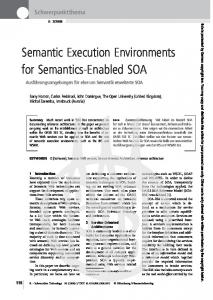
Translating UML-RT models into Circus can then benefit from the formal semantics as well as the refinement notions and laws of Circus. For example, the meaning of capsule refinement is interpreted as process refinement in Circus. Similarly, action refinement can be used to capture statechart transformations. As illustration, we present one transformation law that involves the three most important diagrams of UML-RT: state, class and structure diagrams. As previously mentioned, we consider structure diagrams because they represent some relations between capsules that are not expressed in class diagrams; so they must be taken into account to preserve the model behaviour. Law 1 decomposes a capsule A into parallel component capsules (B and C) in order to tackle design complexity and to potentially improve reuse. The side condition requires that A must be partitioned, a concept that is explained next. On the left-hand side of Law 1 the state machine of A is an And-State composed of two states (Sb and Sc), which may interact (internal communication) through the conjugated ports b2 and c1 (as captured by the structure diagram on the left-hand side). The other two ports (b1 and c2 ) are used for external communication by states Sb and Sc, respectively. Furthermore, in transitions on Sb, only the attributes batts and the methods bmeths (that may reference only the attributes batts) are used; analogously, transitions of Sc use only the attributes catts and the methods cmeths (that may reference only the attributes catts). Finally, the invariant of A is the conjunction InvB ∧ InvC , where InvB involves only batts as free variables, and InvC only catts. When a capsule obeys such conditions, we say that it is partitioned. In this case, there are two partitions: one is hbatts, InvB , bmeths, (b1 , b2 ), Sbi and the other is hcatts, InvC , cmeths, (c1 , c2 ), Sci.
Law 1. Capsule Decomposition
provided hbatts, InvB , bmeths, (b1 , b2 ), Sbi and hcatts, InvC , cmeths, (c1 , c2 ), Sci partition A; The statecharts of the protocol X and Z are deterministic. The effect of the decomposition is to create two new component capsules, B and C, one for each partition, and redesign the original capsule A to act as a mediator. In general, the new behaviour of A might depend on the particular form of decomposition. Law 1 captures a parallel decomposition. On the righthand side of the law, A has no state machine. It completely delegates its original behaviour to B and C through the structure diagram. Concerning the structure diagram on the right-hand side of the law, it shows how A encapsulates B and C. When A is created, it automatically creates the instances of B and C, which execute concurrently. The public ports b1 and c2 are preserved in A. Capsule B has as its public port an image of b1 , called b01 . Although this port is public in B, it is only visible inside the structure diagram of A. The role of this port is to allow B to receive the external signals received from A through port b1 , as captured by the connection between b01 and b1 in the structure diagram of A. Analogously, c2 and b02 have the same relationship, concerning capsules A and C. The internal ports b2 and c1 are moved to capsules B and C, respectively, and play the same role as before. 5.1
Soundness
Based on the semantic mapping presented in Section 4, we can translate the two sides of Law 1 and check its validity. Instead of appealing directly to the semantics of Circus we can use its refinement laws [12] to carry out the proof. Actually, Law 1 has been inspired by the following law presented for Circus. Obviously, when there are no corresponding laws in Circus, it might be necessary to carry out the proof directly in the Circus UTP semantics. Even when there is a corresponding law in Circus, we will see that the proof is more elaborate than using just this law, since we consider structure diagrams.
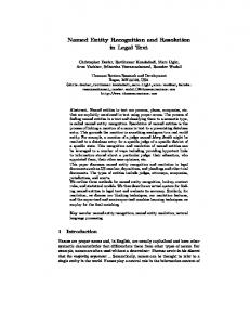
Law 2. Process splitting Let qd and rd stand for the declarations of the processes Q and R, determined by Q.st, Q.pps, and Q.act, and R.st, R.pps, and R.act, respectively; let F stand for a context which must also make sense as a function on processes. Then process P = b begin = (qd rd processP = b F (Q, R)) state State = b Q.st ∧ R.st Q.pps ↑ R.st R.pps ↑ Q.st • F (Q.act, R.act) end provided Q.pps and R.pps are disjoint with respect to R.st and Q.st. 2
In Law 2, the state of P is defined as the conjunction of two other state schemas: Q.st and R.st. The actions of P are Q.pps ↑ R.st and R.pps ↑ Q.st, which handle the partitions of the state separately. In Q.pps ↑ R.st, each schema expression of Q.pps is conjoined with ΞR.st; this means that the state components of R.st do not change (similarly for R.pps ↑ Q.st). Two sets of process paragraphs pps1 and pps2 are disjoint with respect to states s1 and s2 if, and only if, no command nor CSP action expression in pps1 refers to components of s2 or to paragraph names in pps2 ; similarly, for pps2 and components of s2 . Proof of Law 1. First we deal with the class and the state diagrams. The mapping of these views of capsule A as a Circus process is obtained by using the second mapping rule presented in Section 4.1 and the last rule of Section 4.2. We write two partitions using the operator ↑, as in Law 2. Strictly, the attributes and methods batts, catts, bmeths and cmeths must be mapped using the function TL(); here we omit its application for a matter of readability. process ChartA = b begin state State = b [batts ∧ catts | InvB ∧ InvC ] bmeths ↑ catts cmeths ↑ batts • H(SB )[b2 := k] |[ batts | {| k, b1 , c2 |} | catts]|)H(SC )[c1 := k] end
From Law 2, the following equality holds: ChartA = ChartB [b2 := k] |[ {| k, b1 , c2 |} ]| ChartC [c1 := k]
where ChartB and ChartB are declared as: process ChartB = b begin state State = b [batts | InvB ] bmeths • H(SB ) end process ChartC = b begin state State = b [catts | InvC ] cmeths • H(SC ) end
Now we consider the structural part of capsule A. This is mapped into the Circus process StructA , presented below. StructA = b (ChartA [b2 , c1 := k, k] |[{| k,b1 ,c2 |}]| X[chanX := b1 ] |[{| k,b1 ,c2 |}]| Y[chanY := k] |[{| k,b1 ,c2 |}]| Y[chanY := k] |[{| k,b1 ,c2 |}]| Z[chanZ := c2 ]) \ {| k |}
The structure diagrams of B and C, as well as that of A on the right-hand side of Law 1, are mapped similarly. To avoid confusion between the two occurrences of A in the law, we refer to the occurrence on the left simply as A, and that on the right as A0 . Therefore, we want to prove that StructA has the same behaviour as StructA0 , where the latter is composed of the processes StructB and StructC : StructA0 = b ((StructB [b0 1 , b2 := m, k ] |[ {| k |} ]| StructC [c0 2 , c1 := n, k ]) |[ {| k |}]| (X[chanX := m] |[ {| k |} ]| Z[chanZ := n]))[m, n := b1 , c2 ] \ {| k |}
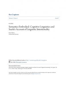
The proof uses basic laws of CSP [5], which are also valid for Circus. One of the laws is the distribution of injective renaming through parallel composition; this is expressed as f (P |[ cs ]| Q) = (f (P ) |[ f (cs) ]| f (Q)) and referenced as f [.]−|[cs ]|−dist. Two other laws express the associativity (P |[ cs ]| (Q |[ cs ]| R) = (P |[cs]|Q)|[cs]|R) and the symmetry (P |[cs]|Q = Q |[cs]|P ) of parallel composition. These are referenced bellow as |[cs ]|−assoc and |[cs ]|−sym, respectively. Also, we use the fact that unused channels in the synchronism of a parallel operator are redundant, which is expressed as P |[αP ∪ αQ ∪ cs ]| Q = P |[αP ∪ αQ ]| Q, where αR is the alphabet of R; we refer this law as |[cs ]|−null . Finally, we use the fact that the parallel operator is idempotent under certain restrictions [21]: if P is a deterministic process, then P = P |[ αP ]| P ; this law is referenced as |[cs ]|−idem. StructA = [1. Expanding ChartA in StructA ] (ChartB [b2 := k] |[{| k,b1 ,c2 |}]|ChartC [c1 := k] |[{| k,b1 ,c2 |}]|X[chanX := b1 ] |[{| k,b1 ,c2 |}]| Y[chanY := k] |[{| k,b1 ,c2 |}]| Y[chanY := k] |[{| k,b1 ,c2 |}]| Z[chanZ := c2 ]) \ {| k |} = [2. Applying Law |[ cs ]|−idem for X[chanX := b1 ] and Z[chanZ := c2 ], and rearranging the processes using Laws |[ cs ]|−assoc and |[ cs ]|−sym] (ChartB [b2 := k] |[{| k,b1 ,c2 |}]|X[chanX := b1 ] |[{| k,b1 ,c2 |}]|Y[chanY := k] |[{| k,b1 ,c2 |}]| X[chanX := b1 ] |[{| k,b1 ,c2 |}]| ChartC [c1 := k] |[{| k,b1 ,c2 |}]| Y[chanY := k] |[{| k,b1 ,c2 |}]| Z[chanZ := c2 ] |[{| k,b1 ,c2 |}]| Z[chanZ := c2 ]) \ {| k |} = [3. Applying renamings [b0 1 ,b2 := m,k], [c0 2 ,c1 := n,k] and [n,m := c2 ,b1 ], and Law f [.]−|[cs ]|−dist]] (((ChartB |[{| b2 ,b0 1 ,n |}]|X[chanX := b0 1 ] |[{| b2 ,b0 1 ,n |}]|Y[chanY := b2 ])[b0 1 ,b2 := m,k] |[{| k,m,n |}]| X[chanX := m]) |[{| k,m,n |}]| ((ChartC |[{| c1 ,m,c0 2 |}]| Y[chanY := c1 ] |[{| c1 ,m,c0 2 |}]| Z[chanZ := c0 2 ])[c0 2 ,c1 := n,k] |[{| k,m,n |}]| Z[chanZ := n])[m,n := b1 ,c2 ]) \ {| k |} = [4. Using the Law |[ cs ]|−null and rearranging the processes using laws ] |[cs ]|−assoc and |[ cs ]|−sym (((ChartB |[{| b2 ,b0 1 |}]|X[chanX := b0 1 ] |[{| b2 ,b0 1 |}]|Y[chanY := b2 ])[b0 1 ,b2 := m,k] |[{| k,m,n |}]| ((ChartC |[{| c1 ,c0 2 |}]|Y[chanY := c1 ] |[{| c1 ,c0 2 |}]|Z[chanZ := c0 2 ])[c0 2 ,c1 := n,k] |[{| k,m,n |} ]| X[chanX := m]) |[ {| k,m,n |}]| Z[chanZ := n])[m,n := b1 ,c2 ]) \ {| k |} = [5. Using the definition of StructB and StructC ] ((StructB [b0 1 ,b2 := m,k] |[{| k,m,n |}]| (StructC [c0 2 ,c1 := n,k] |[{| k,m,n |}]| X[chanX := m]) |[{| k,m,n |} ]| Z[chanZ := n])[m,n := b1 ,c2 ]) \ {| k |} = StructA0
Three conditional CSP laws are used in the above proof. The condition of Law |[cs]|−idem (Step 2) is clearly satisfied because the processes X and Z are obtained from the protocols X and Z, which, in Law 1, are assumed to be deterministic. The condition of Law |[cs ]|−null (Step 4) is satisfied since the processes ChartB , X[chanX := b0 1 ] and Y[chanY := b2 ] do not use the channel n; similarly, processes ChartC , Y[chanY := c1 ] and Z[chanZ := c0 2 ] do not use m. The condition of Law f [.]−|[cs ]|−dist (Step 3) is satisfied since following renamings used in the distribution are injective: [b0 1 ,b2 := m,k], [c0 2 ,c1 := n,k] and [n,m := c2 ,b1 ]
6
Conclusions
We have proposed a formal semantics for capsules, protocols, ports and connections in UML-RT, using Circus as a semantic domain. We considered an
integrated view involving UML-RT class, state and structure diagrams. Also, we presented a transformation law for capsule decomposition that considers the effect on all these diagrams. Based on the semantic mapping, and on the semantics and laws of Circus, we have shown that it is relatively simple to prove such laws. As far as we are aware, an entirely formal approach to transformation of UML-RT models is an original contribution. Although the target of our translation is a specification language (rather than a more standard mathematical model), the notation of Circus includes those of CSP and Z. Both are well-known and mature formalisms. Further, their combination into Circus is formally characterised with basis on the unifying theories of programming [20]. The basis for the translation given in this paper is a formalisation of the syntax of UML-RT in Z and in CSP. The formalisation of UML-RT structure diagrams is similar to [8], which formalises only this kind of diagram in CSP, and disregards other views and elements of the architecture, as statecharts and protocols. The work reported in [9] briefly presents some notions that could be used as a basis for a mapping from UML-RT into CSP, but based on these notions it seems rather difficult mapping complex systems in all its aspects without additional assumptions on the dynamic semantics. It briefly covers simple capsule statecharts, and does not give any additional contribution on the capsuleconnector-capsule translation when compared to [8]. An informal translation of UML-RT to CSP-OZ is also reported in [7] through a case study. Despite the benefit of linking UML-RT to CSP-OZ and Java, the work in [7] does note seem concerned with the soundness of transformations for UML-RT, but rather with platform transformations between these languages. A more general contextualisation of our work has already been given in Section 1. Currently, we are working on a comprehensive set of laws for UML-RT, exploring their use during the development of a more elaborate version of the example presented in Section 2. Our notion of completeness is based on showing that an arbitrary UML-RT model can be reduced to a UML model extended with a single capsule responsible for all the interactions with the environment. This extended UML model can be regarded as a normal form, and therefore relative completeness of our set of laws can be captured by normal form reduction, following an approach similar to [22]. In general, the laws involve classes and relationships between them as well as with capsules. The semantics of OhCircus [23] is being defined as a conservative extension of that of Circus, to address object-oriented features. We plan to extend our mapping to consider the full UML-RT notation, using OhCircus as semantic domain.
References 1. Object Management Group: OMG Unified Modeling Language Specification. (2003) OMG document formal/03-03-01. 2. Bruel, J.M., France, R., Larrondo-Petrie, M.: An integrated object-oriented and formal modeling environment. Journal of Object-Oriented Programming 10 (1997)
3. Ng, M.Y., Butler, M.J.: Towards Formalizing UML State Diagrams in CSP. In: 1st International Conference on Software Engineering and Formal Methods, IEEE Computer Society (2003) 138–147 4. Spivey, M.: The Z Notation: A Reference Manual. second edn. Prentice Hall (1992) 5. Roscoe, A.W.: The Theory and Practice of Concurrency. Prentice-Hall (1998) 6. Amalio, N., Polack, F.: Comparison of formalisation approaches of UML class constructs in Z and Object-Z. In: Third International Conference of B and Z. Volume 2651 of LNCS. (2003) 7. M¨ oller, M., Olderog, E.R., Rasch, H., Wehrheim, H.: Linking CSP-OZ with UML and Java: A Case Study. In: 4th International Conference on Integrated Formal Methods. Volume 2999 of LNCS., Springer (2004) 8. Fischer, C., Olderog, E.R., Wehrheim, H.: A CSP View on UML-RT Structure Diagrams. In: 4th International Conference on Fundamental Approaches to Software Engineering, Springer (2001) 9. Engels, G., K¨ uster, J.M., Heckel, R., Groenewegen, L.: A methodology for specifying and analyzing consistency of object-oriented behavioral models. In: Proceedings of the 8th European Software engineering Conference, ACM Press (2001) 10. Selic, B., Rumbaugh, J.: Using UML for Modeling Complex RealTime Systems. Rational Software Corporation (1998) available at http://www. rational.com. 11. Engels, G., Heckel, R., K¨ uster, J.M., Groenewegen, L.: Consistency-Preserving Model Evolution through Transformations. In: 5th International Conference on the Unified Modeling Language. Volume 2460 of LNCS., Springer (2002) 12. Sampaio, A., Woodcock, J., Cavalcanti, A.: Refinement in Circus. In: International Symposium of Formal Methods Europe. Volume 2391 of LNCS., Springer (2002) 13. Hoare, C.A.R., Jifeng, H.: Unifying Theories of Programming. Prentice-Hall (1998) 14. Fischer, C.: Combination and Implementation of Processes and Data: from CSPOZ to Java. PhD thesis, Fachbereich Informatik Universit¨ at Oldenburg (2000) 15. Morgan, C.: Programming from Specifications. second edn. Prentice Hall (1994) 16. Sampaio, A., Mota, A., Ramos, R.: Class and Capsule Refinement in UML for Real Time. In: Proceedings of the Brazilian Workshop on Formal Methods. Volume 95 of ENTCS. (2004) 17. Object Management Group: OMG Adopted Specification. (2003) OMG documents ptc/03-09-15 and ptc/03-08-02. 18. Richters, M., Gogolla, M.: OCL: Syntax, Semantics, and Tools. In: Object Modeling with the OCL: The Rationale behind the Object Constraint Language. Springer (2002) 19. Selic, B.: An Efficient Object-Oriented Variation of the Statecharts Formalism for Distributed Real-Time Systems. In: 11th IFIP WG10.2 International Conference on Computer Hardware Description Languages and their Applications. Volume A-32 of IFIP Transactions. (1993) 20. Woodcock, J., Cavalcanti, A.: The Semantics of Circus. In: ZB 2002: Formal Specification and Development in Z and B. Volume 2272 of LNCS., Springer (2002) 21. Hoare, C.A.R.: Communicating Sequential Processes. Prentice-Hall (1985) 22. Borba, P., Sampaio, A., Cavalcanti, A., Corn´elio, M.: Algebraic reasoning for object-oriented programming. Science of Computer Programming 52 (2004) 23. Cavalcanti, A., Sampaio, A., Woodcock, J.: A unified language of classes and processes. In: St Eve: State-Oriented vs. Event-Oriented Thinking in Requirements Analysis, Formal Specification and Software Engineering, Satellite Workshop at FM’03 (2003)