1. INTRODUCTION. The memory subsystem is a key element of any compu- ... memories do not add functionality to the systemâall stor- ... dimensional array of homogeneous processing elements as ..... the code that generates memory requests, and the code that reads and writes data is partitioned appropriately. mem rd() ...
Hindawi Publishing Corporation EURASIP Journal on Embedded Systems Volume 2007, Article ID 86273, 13 pages doi:10.1155/2007/86273
Research Article A Shared Memory Module for Asynchronous Arrays of Processors Michael J. Meeuwsen, Zhiyi Yu, and Bevan M. Baas Department of Electrical and Computer Engineering, University of California, Davis, CA 95616-5294, USA Received 1 August 2006; Revised 20 December 2006; Accepted 1 March 2007 Recommended by Gang Qu A shared memory module connecting multiple independently clocked processors is presented. The memory module itself is independently clocked, supports hardware address generation, mutual exclusion, and multiple addressing modes. The architecture supports independent address generation and data generation/consumption by different processors which increases efficiency and simplifies programming for many embedded and DSP tasks. Simultaneous access by different processors is arbitrated using a least-recently-serviced priority scheme. Simulations show high throughputs over a variety of memory loads. A standard cell implementation shares an 8 K-word SRAM among four processors, and can support a 64 K-word SRAM with no additional changes. It cycles at 555 MHz and occupies 1.2 mm2 in 0.18 µm CMOS. Copyright © 2007 Michael J. Meeuwsen et al. This is an open access article distributed under the Creative Commons Attribution License, which permits unrestricted use, distribution, and reproduction in any medium, provided the original work is properly cited.
1.
INTRODUCTION
The memory subsystem is a key element of any computational machine. The memory retains system state, stores data for computation, and holds machine instructions for execution. In many modern systems, memory bandwidth is the primary limiter of system performance, despite complex memory hierarchies and hardware driven prefetch mechanisms. Coping with the intrinsic gap between processor performance and memory performance has been a focus of research since the beginning of the study of computer architecture [1]. The fundamental problem is the infeasibility of building a memory that is both large and fast. Designers are forced to reduce the sizes of memories for speed, or processors must pay long latencies to access high capacity storage. As memory densities continue to grow, memory performance has improved only slightly; processor performance, on the other hand, has shown exponential improvements over the years. Processor performance has increased by 55 percent each year, while memory performance increases by only 7 percent [2]. The primary solution to the memory gap has been the implementation of multilevel memory hierarchies. In the embedded and signal processing domains, designers may use existing knowledge of system workloads to optimize the memory system. Typically, these systems have
smaller memory requirements than general purpose computing loads, which makes alternative architectures attractive. This work explores the design of a memory subsystem for a recently introduced class of multiprocessors that are composed of a large number of synchronous processors clocked asynchronously with respect to each other. Because the processors are numerous, they likely have fewer resources per processor, including instruction and data memory. Each processor operates independently without a global address space. To efficiently support applications with large working sets, processors must be provided with higher capacity memory storage. The Asynchronous Array of simple Processors (AsAP) [3] is an example of this class of chip multiprocessors. To maintain design simplicity, scalability, and computational density, a traditional memory hierarchy is avoided. In addition, the low locality in tasks such as those found in many embedded and DSP applications, makes the cache solution unattractive for these workloads. Instead, directlyaddressable software-managed memories are explored. This allows the programmer to efficiently manage the memory hierarchy explicitly. The main requirements for the memory system are the following: (1) the system must provide high throughput access to high capacity random access memory,
2
EURASIP Journal on Embedded Systems (2) the memory must be accessible from multiple asynchronous clock domains, (3) the design must easily scale to support arbitrarily large memories, and (4) the impact on processing elements should be minimized.
The remainder of this work is organized as follows. In Section 2, the current state of the art in memory systems is reviewed. Section 3 provides an overview of an example processor array without shared memories. Section 4 explores the design space for memory modules. Section 5 describes the design of a buffered memory module, which has been implemented using a standard cell flow. Section 6 discusses the performance and power of the design, based on high level synthesis results and simulation. Finally, the paper concludes with Section 7. 2.
BACKGROUND
2.1. Memory system architectures Although researchers have not been able to stop the growth of the processor/memory gap, they have developed a number of architectural alternatives to increase system performance despite the limitations of the available memory. These solutions range from traditional memory hierarchies to intelligent memory systems. Each solution attempts to reduce the impact of poor memory performance by storing the data needed for computation in a way that is easily accessible to the processor. 2.1.1. Traditional memory hierarchies The primary solution to the processor/memory gap has been to introduce a local cache memory, exploiting spatial and temporal locality evident in most software programs. Caches are small fast memories that provide the processor with a local copy of a small portion of main memory. Caches are managed by hardware to ensure that the processor always sees a consistent view of main memory. The primary advantage of the traditional cache scheme is ease of programming. Because caches are managed by hardware, programs address a single large address space. Movement of data from main memory to cache is handled by hardware and is transparent to software. The primary drawback of the cache solution is its high overhead. Cache memories typically occupy a significant portion of chip area and consume considerable power. Cache memories do not add functionality to the system—all storage provided is redundant, and identical data must be stored elsewhere in the system, such as in main memory or on disk. 2.1.2. Alternative memory architectures Scratch Pad Memories are a cache alternative not uncommonly found in embedded systems [4]. A scratch-pad memory is an on-chip SRAM with a similar size and access time as an L1 (level 1) cache. Scratch pad memories are unlike caches
Single processor Osc. (a)
(b)
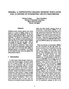
Figure 1: Block diagram and chip micrograph of the AsAP chip multiprocessor.
in that they are uniquely mapped to a fixed portion of the system’s address space. Scratch-pad memory may be used in parallel with a cache or alone [5]. Banakar et al. report a typical power savings of 40 percent when scratch-pad memories are used instead of caches [4]. Others have explored alternatives to traditional memory hierarchies. These include architectures such as Intelligent RAM (IRAM) [6] and Smart Memories [7]. 3.
AN EXAMPLE TARGET ARCHITECTURE: AsAP
An example target architecture for this work is a chip multiprocessor called an Asynchronous Array of simple Processors (AsAP) [3, 8, 9]. An AsAP system consists of a twodimensional array of homogeneous processing elements as shown in Figure 1. Each element is a simple CPU, which contains its own computation resources and executes its own locally stored program. Each processing element has a local clock source and operates asynchronously with respect to the rest of the array. The Globally Asynchronous Locally Synchronous (GALS) [10] nature of the array alleviates the need to distribute a high speed clock across a large chip. The homogeneity of the processing elements makes the system easy to scale as additional tiles can be added to the array with little effort. Interprocessor communication within the array occurs through dual-clock FIFOs [11] on processor boundaries. These FIFOs provide the required synchronization, as well as data buffers for rate matching between processors. The interconnection of processors is reconfigurable. Applications are mapped to AsAP by partitioning computation into many small tasks. Each task is statically mapped onto a small number of processing elements. For example, an IEEE 802.11a baseband transmitter has been implemented on a 22-processor array [9], and a JPEG encoder has been implemented on a 9-processor array. AsAP processors are characterized by their very small memory resources. Small memories minimize power and area while increasing the computational density of the array. No memory hierarchy exists, and memory is managed entirely by software. Additionally, there is no global address space, and all interprocessor communication must occur through the processors’ input FIFOs.
Michael J. Meeuwsen et al. Each processor tile contains memory for 64 32-bit instructions and 128 16-bit words. With only 128 words of randomly-accessible storage in each processor, the AsAP architecture is currently limited to applications with small working sets. 4.
DESIGN SPACE EXPLORATION
A wide variety of design possibilities exist for adding larger amounts of memory to architectures like AsAP. This section describes the design space and design selection based on estimated performance and flexibility. In exploring the design space, parameters can be categorized into three roughly orthogonal groups. (1) Physical design parameters, such as memory capacity and module distribution have little impact on the design of the memory module itself, but do determine how the module is integrated into the processing array. (2) Processor interface parameters, such as clock source and buffering have the largest impact on the module design. (3) Reconfigurability parameters allow design complexity to be traded off for additional flexibility. 4.1. Key memory parameters 4.1.1. Capacity Capacity is the amount of storage included in each memory module. Memory capacity is driven by application requirements as well as area and performance targets. The lower bound on memory capacity is given by the memory requirements of targeted applications while die area and memory performance limit the maximum amount of memory. Higher capacity RAMs occupy more die area, decreasing the total computational density of the array. Larger RAMs also limit the bandwidth of the memory core. It is desirable to implement the smallest possible memory required for the targeted applications. These requirements, however, may not be available at design time. Furthermore, over-constraining the memory capacity limits the flexibility of the array as new applications emerge. Hence, the scalability of the memory module design is important, allowing the memory size to be chosen late in the design cycle and changed for future designs with little effort. 4.1.2. Density Memory module density refers to the number of memory modules integrated into an array of a particular size, and is determined by the size of the array, available die area, and application requirements. Typically, the number of memory modules integrated into an array is determined by the space available for such modules; however, application level constraints may also influence this design parameter. Assuming a fixed memory capacity per module, additional modules may be added to meet minimum memory capacity requirements.
3 Also, some performance increase can be expected by partitioning an application’s data among multiple memory modules due to the increased memory bandwidth provided by each module. This approach to increasing performance is not always practical and does not help if the application does not saturate the memory interface. It also requires a high degree of parallelism among data as communication among memory modules may not be practical. 4.1.3. Distribution The distribution of memory modules within the array can take many forms. In general, two topological approaches can be used. The first approach leaves the processor array intact and adds memory modules in rows or columns as allowed by available area resources. Processors in the array maintain connectivity to their nearest neighbors, as if the memory modules were not present. The second approach replaces processors with memory modules, so that each processor neighboring a memory module loses connectivity to one processor. These strategies are illustrated in Figure 2. 4.1.4. Clock source Because the targeted arrays are GALS systems, the clock source for the memory module becomes a key design parameter. In general, three distinct possibilities exist. First, the memory module can derive its clock from the clock of a particular processor. The memory would then be synchronous with respect to this processor. Second, the memory can generate its own unique clock. The memory would be asynchronous to all processors in the array. Finally, the memory could be completely asynchronous, so that no clock would be required. This solution severely limits the implementation of the memory module, as most RAMs provided in standard cell libraries are synchronous. 4.1.5. Address source The address source for a memory module has a large impact on application mapping and performance. To meet the random access requirement, processors must be allowed to supply arbitrary addresses to memory. (1) The obvious solution uses the processor producing or consuming the memory data as the address source. The small size of the targeted processors, however, makes another solution attractive. (2) The address and data streams for a memory access can also be partitioned among multiple processors. A single processor can potentially be used to provide memory addresses, while other processors act as data sources and data sinks. This scheme provides a potential performance increase for applications with complex addressing needs because the data processing and address generation can occur in parallel. (3) A third possible address source is hardware address generators, which typically speed up memory accesses significantly, but must be built into hardware. To avoid unnecessary use of power and die area, only the most commonly used access patterns should be included in hardware.
4
EURASIP Journal on Embedded Systems
Memory Processor
Memory Processor
(a)
Memory Processor
(b)
(c)
Figure 2: Various topologies for distribution of memories in a processor array. Processor connectivity is maintained when (a) memories are added to the edge of the array, or (b) the array is split to make room for a row of memories. Processor connectivity is lost when (c) processor tiles are replaced by memory tiles.
The implementation of buffers for accesses to the memory module provides another design parameter. Buffers may be used between a processor and a memory module for latency hiding, synchronization, or rate matching. Without some level of buffering, processors are tightly coupled to the memory interface, and prefetching of data is difficult.
synchronous to the interfacing processor. Because processors are asynchronous to one another, sharing the memory is no longer feasible, and using an alternate processor as an address source is not possible. The resulting design is a memory module that couples tightly to a single processor. Because there is no buffering, memory accesses are either tightly integrated into the processor’s pipeline or carefully timed to avoid overwriting data.
4.1.7. Sharing
Type II: buffered memory
The potentially large number of processors in a processing array makes the sharing of memories among processors attractive. In this context, shared memory serves two distinct purposes. First, as in more traditional computing, shared memory can serve as a communication medium among simultaneous program threads. Also, in our context, sharing a memory among multiple processors can enable higher utilization of available memory bandwidth in cases where a single thread is unable to saturate the memory bus. In either case, synchronization mechanisms are required to guarantee mutual exclusion when memory is shared.
The second design is, in some respects, the dual of the first. We can arrive at this design by requiring that the memories be shareable. Because processors exist in different clock domains, dual-clock FIFOs must be used to synchronize across clock boundaries. To avoid tying the memory clock speed to an arbitrary processor (which would defeat the fundamental purpose of GALS clocking—namely, to allow independent frequency adjustment of blocks), the memory module should supply its own clock. An independent processor could easily be used as an address source with the appropriate hardware in place. This design effectively isolates the memory module from the rest of the array, has few dependencies on the implementation of the processors, and does not impact the performance of any processors not accessing the memory.
4.1.6. Buffering
4.1.8. Inter-parameter dependencies There are strong dependencies among the four parameters described in the preceding four subsections (clock source, address source, buffering, and sharing). Selecting a value for one of the parameters limits the feasible values of the other parameters. This results in the existence of two distinct archetype designs for the processor interface. Other design options tend to be hybrids of these two models and often have features that limit usefulness. Type I: bufferless memory The first design can be derived by forcing a bufferless implementation. Without buffers, there is no way to synchronize across clock boundaries, so the memory module must be
4.2.
Degree of configurability
The degree of configurability included in the memoryprocessor interconnect, as well as in the memory module itself can be varied independently of the memory module design. To some degree, the level of configurability required in the interconnect is a function of the number of processors in the array, and their distances from the memory module. For small arrays, hardwired connections to the memory module may make sense. For large arrays with relatively few memory modules, additional configurability is desirable to avoid limiting the system’s flexibility.
Michael J. Meeuwsen et al. The configurability of the memory module itself allows trade offs in performance, power, and area for flexibility. Examples of configurability at the module level cover a broad range and are specific to the module’s design. Some examples of configurable parameters are the address source used for memory accesses and the direction of synchronization FIFOs in a locally clocked design. 4.3. Design selection The remainder of this work describes a buffered memory solution. This design was chosen based on the flexibility in addressing modes and the ability to share the memory among multiple processors. These provide a potential performance increase by allowing redistribution of the address generation workload, and by exploiting parallelism across large datasets. The relative area overhead impact of the additional logic can be reduced if the RAM core used in the memory module has a high capacity and thus the FIFO buffers become a small fraction of the total module area. The performance impact of additional memory latency can potentially be reduced or eliminated by appropriate software task partitioning or techniques such as data prefetching. 5.
FIFO-BUFFERED MEMORY DESIGN
This section describes the design and implementation of a FIFO-buffered memory module suitable for sharing among independently-clocked interfaces (typically processors). The memory module has its own local clock source, and communicates with external blocks via dual clock FIFOs. As described in Section 4.3, this design was selected based on its flexibility in addressing modes and the potential speedup for applications with a high degree of parallelism across large datasets. 5.1. Overview The prototype described in this section allows up to four external blocks to access the RAM array. The design supports a memory size up to 64 K 16-bit words with no additional modifications. Processors access the memory module via input ports and output ports. Input ports encapsulate the required logic to process incoming requests and utilize a dual-clock FIFO to reliably cross clock domains. Each input port can assume different modes, changing the method of memory access. The memory module returns data to the external block via an output port, which also interfaces via a dual-clock FIFO. A number of additional features are integrated into the memory module to increase usability. These include multiple port modes, address generators, and mutual exclusion (mutex) primitives. A block diagram of the FIFO-buffered memory is shown in Figure 3. This diagram shows the high-level interaction of the input and output ports, address generators, mutexes, and SRAM core. The theory of operation for this module is described in Section 5.2. The programming interface to the memory module is described in Section 5.3.
5 5.2.
Theory of operation
The operation of the FIFO-buffered memory module is based on the execution of requests. External blocks issue requests to the memory module by writing 16-bit command tokens to the input port. The requests instruct the memory module to carry out particular tasks, such as memory writes or port configuration. Additional information on the types of requests and their formats is provided in Section 5.3. Incoming requests are buffered in a FIFO queue until they can be issued. While requests issued into a single port execute in FIFO order, requests from multiple processors are issued concurrently. Arbitration among conflicting requests occurs before allowing requests to execute. In general, the execution of a request occurs as follows. When a request reaches the head of its queue it is decoded and its data dependencies are checked. Each request type has a different set of requirements. A memory read request, for example, requires adequate room in the destination port’s FIFO for the result of the read; a memory write, on the other hand, must wait until valid data is available for writing. When all such dependencies are satisfied, the request is issued. If the request requires exclusive access to a shared resource, it requests access to the resource and waits for acknowledgment prior to execution. The request blocks until access to the resource is granted. If the request does not access any shared resources, it executes in the cycle after issue. Each port can potentially issue one request per cycle, assuming that requests are available and their requirements are met. The implemented memory module supports all three address sources detailed in Section 4.1.5. These are (1) one processor providing addresses and data, (2) two processors with one providing addresses and the other handling data, and (3) hardware address generators. All three support bursts of 255 memory reads or writes with a single request. These three modes provide high efficiency in implementing common access patterns without preventing less common patterns from being used. Because the memory resources of the FIFO-buffered memory are typically shared among multiple processors, the need for interprocess synchronization is anticipated. To this end, the memory module includes four mutex primitives in hardware. Each mutex implements an atomic single-bit test and set operation, allowing easy implementation of simple locks. More complex mutual exclusion constructs may be built on top of these primitives using the module’s memory resources. 5.3.
Processor interface
External blocks communicate with the memory module via dedicated memory ports. Each of these ports may be configured to connect to one input FIFO and one output FIFO in the memory module. These connections are independent, and which of the connections are established depends on the size of the processor array, the degree of reconfigurability implemented, and the specific application being mapped. An external block accesses the memory module by writing 16-bit words to one of the memory module’s input
6
EURASIP Journal on Embedded Systems
rdy, ack, priority Input port
Priority arbitration
Output FIFO
addr, data, rden, wren Input port
addr, data, rden, wren addr, data, rden, wren
Mutex Input port
req, rel grant, priority
Mutex
SRAM
brst ld, brst data, brst en, brst addr, brst done
addr, data, rden, wren
Output FIFO
Mutex Mutex
Output FIFO
Input port Output FIFO
Address generator cfg wren, addr, data Address generator
Figure 3: FIFO-buffered memory block diagram. Arrows show the direction of signal flow for the major blocks in the design. Multiplexers allow control of various resources to be switched among input ports. The gray bars approximate the pipeline stages in the design.
FIFOs. In general, these words are called tokens. One or more tokens make up a request. A request instructs the memory module to perform an action and consists of a command token, and possibly one or more data tokens. The requests issued by a particular processor are always executed in FIFO order. Concurrent requests from multiple processors may be executed in any order. If a request results in data being read from memory, this data is written to the appropriate output FIFO where it can be accessed by the appropriate block. 5.3.1. Request types The FIFO-buffered memory supports eight different request types. Each request type utilizes different resources within the memory module. In addition, some requests are blocking, meaning that they must wait for certain conditions to be satisfied before they complete. To maintain FIFO ordering of requests, subsequent requests cannot proceed until a blocking request completes. (1)-(2) Memory read and write requests cause a single word memory access. The request blocks until the access is completed. (3)-(4) Configuration requests enable setup of module ports and address generators. (5)-(6) Burst read and write requests are used to issue up to 255 contiguous memory operations using an address generator. (7)-(8) Mutex request and release commands are used to control exclusive use of a mutual exclusion primitive—which can be used for
synchronization among input ports or in the implementation of more complex mutual exclusion constructs. 5.3.2. Input port modes Each input port in the FIFO-buffered memory module can operate in one of three modes. These modes affect how incoming memory and burst requests are serviced. Mode information is set in the port configuration registers using a port configuration request. These registers are unique to each input port, and can only be accessed by the port that contains them. Address-data mode is the most fundamental input port mode. In this mode, an input port performs memory reads and writes independently. The destination for memory reads is programmable, and is typically chosen so that the output port and input port connect to the same external block, but this is not strictly required. A memory write is performed by first issuing a memory write request containing the write address. This request must be immediately followed by a data token containing the data to be written to memory. In the case of a burst write, the burst request must be immediately followed by the appropriate number of data tokens. Figure 4(a) illustrates how writes occur in address-data mode. A memory read is performed by first issuing a memory read request, which contains the read address. The value read
Michael J. Meeuwsen et al.
7
Processor
. . .
Data Data Burst write req. Data Write req. Data Write req.
Memory module Input token stream Address-data mode Write req. To memory Data
(a)
. ..
. ..
. ..
Write req. Write req.
Processor 0
Burst write req. Write req. Write req.
Memory module Input token stream Address-only mode
. . .
Data-only mode To memory
Data Data Data Data
Processor 1
Data Data Data
Input token stream
Write req.
Data
(b)
Figure 4: Memory writes in (a) address-data and (b) address-only mode. (a) In address-data mode, each port provides both addresses and data. Memory writes occur independently, and access to the memory is time-multiplexed. Two tokens must be read from the same input stream to complete a write. (b) In address-only mode, write addresses are supplied by one port, and data are supplied by another. Memory writes are coupled, so there is no need to time-multiplex the memory among ports. One token must be read from each input stream to complete a write.
from memory is then written to the specified output FIFO. The same destination is used for burst reads. In address-only mode, an input port is paired with an input port in data-only mode to perform memory writes. This allows the tasks of address generation and data generation to be partitioned onto separate external blocks. In address-only mode, a memory write is performed by issuing a memory write request containing the write address. In contrast to operation in address-data mode, however, this request is not followed by a data token. Instead, the next valid data token from the input port specified by a programmable configuration register is written to memory. Synchronization between input ports is accomplished by maintaining FIFO order of incoming tokens. It is the programmer’s responsibility to ensure that there is a one to one correspondence between write requests in the address-only port and data tokens in the data-only port. Figure 4(b) illustrates how writes occur. An input port in data-only mode acts as a slave to the address-only input port to which it provides data. All request types, with the exception of port configuration requests, are ignored when the input port is in data-only mode. Instead all incoming tokens are treated as data tokens. The programmer must ensure that at any one time, at most one input port is configured to use a data-only port as a data source.
As previously mentioned, the presented memory module design directly supports memory arrays up to 64 K words. This is due solely to a 16-bit interface in the AsAP processor, and therefore a 16-bit memory address in a straightforward implementation. The supported address space can clearly be increased by techniques such as widening the interface bus or implementing a paging scheme. Another dimension of memory module scaling is to consider connecting more than four processors to a module. This type of scaling begins to incur significant performance penalties (in tasks such as port arbitration) as the number of ports scales much beyond four. Instead, the presented memory module is much more amenable to replication throughout an array of processors—providing high throughput to a small number of local processors while presenting no barriers to the joining of multiple memories through software or interconnect reconfiguration, albeit with a potential increase in programming complexity depending on the specific application. 6.
IMPLEMENTATION RESULTS
The FIFO-buffered memory module described in Section 5 has been described in Verilog and synthesized with a 0.18 µm CMOS standard cell library. A standard cell implementation
8
Figure 5: Layout of a 8192-word × 16-bit 0.18 µm CMOS standard cell FIFO-buffered memory module implementation. The large SRAM is at the top of the layout and the eight 32-word FIFO memories are visible in the lower region.
has been completed and is shown in Figure 5. The design is fully functional in simulation. Speed, power, and area results were estimated from highlevel synthesis. In addition, the design’s performance was analyzed with RTL level simulation. This section discusses these results.
EURASIP Journal on Embedded Systems latency, and the additional latency introduced by the memory port. In the memory’s clock domain, the latency includes one FIFO read latency, the memory module latency, and one FIFO write latency. The minimum latency of the memory module is given by the number of pipe stages between the input and output ports. The presented implementation has four pipe stages. The number of stages may be increased to add address decoding stages for larger memories. The latency of FIFO reads and writes is dependent on the number of pipe stages used to synchronize data across the clock boundary between the read side and the write side. In AsAP’s FIFO design, the number of synchronization stages is configurable at runtime. When a typical value of three stages is used, the total FIFO latency is four cycles per side. When the minimum number of stages is used, the latency is reduced to three cycles per side. A latency of four cycles is assumed in this work. The latency of the memory port depends on the number of stages introduced between the processor and the memory to account for wire delays. The minimum latency of the memory port is two cycles. This latency could be decreased by integrating the memory port more tightly with the processor core datapath. This approach hinders the use of a prefetch buffer to manage an arbitrary latency from processor to memory, and is only practical if the latency can be constrained to a single cycle. Summing the latency contributions from each clock domain, the total latency of a memory read is,
6.1. Performance results System performance was the primary metric motivating the memory module design. Two types of performance are considered. First, the system’s peak performance, as dictated by the maximum clock frequency, peak throughput, and latency is calculated. A more meaningful result, however, is the performance of actual programs accessing the memory. Both of these metrics are discussed in the following subsections. 6.1.1. Peak performance The peak performance of the memory module is a function of the maximum clock frequency, and the theoretical throughput of the design. The FIFO-buffered memory module is capable of issuing one memory access every cycle, assuming that requests are available and their data dependencies are met. In address-data mode, memory writes require a minimum of two cycles to issue, but this penalty can be avoided by using address generators or the address-only port mode, or by interleaving memory requests from multiple ports. If adequate processing resources exist to supply the memory module with requests, the peak memory throughput is one word access per cycle. Synthesis results report a maximum clock frequency of 555 MHz. At this clock speed, the memory’s peak throughput is 8.8 Gbps with 16-bit words. The worst case memory latency is for the memory read request. There are contributions to this latency in each of the system’s clock domains. In the external block’s clock domain, the latency includes one FIFO write latency, one FIFO read
Lproc = LFIFO-wr + LFIFO-rd + Lmem-port , Lmem = LFIFO-rd + Lmem-module + LFIFO-wr , Ltotal = Lmem + Lproc .
(1)
For the presented design and typical configurations, the latency is 10 processor cycles and 13 memory cycles. If the blocks are clocked at the same frequency, this is a minimum latency of 23 cycles. Additional latency may be introduced by processor stalls, memory access conflicts, or data dependencies. The latency is slightly higher than typical L2 cache latencies, which are on the order of 15 cycles [2], due to the communication overhead introduced by the FIFOs. This high latency can be overcome by issuing multiple requests in a single block. Because requests are pipelined, the latency penalty occurs only once per block. 6.1.2. Actual performance To better characterize the design’s performance, the memory module was exercised with two generic and variable workloads: a single-element workload and a block workload. The number of instructions in both test kernels is varied to simulate the effect of varying computation loads for each application. Figure 6 gives pseudocode for the two workloads. The single-element workload performs a copy of a 1024element array and contains three phases. First, a burst write
Michael J. Meeuwsen et al.
9
⎡
⎡
for i = 0 : 1023 ⎢ mem wr(a + i) // wr command ⎢ Write initial array ⎢ ⎣ wr data = input // wr data
⎡
next i for i = 0 : 1023 mem rd(a + i) // rd command mem wr(b + i) // wr command
NOP # NOPs models ⎢ additional ⎣ ··· computation load NOP temp = rd data // rd data wr data = temp // wr data next i
NOP # NOPs models ⎢ additional address ⎣ · · · NOP computation load ⎡
Read result
next i
mem wr(a + i) // wr command
NOP # NOPs models ⎢ additional data ⎣ ··· NOP computation load
⎡
wr data = input // wr data next i
NOP # NOPs models ⎢ additional address ⎣ · · · NOP computation load
⎡
for i = 0 : 1023 ⎢ mem rd(b + i) // rd command ⎢ ⎢ ⎣ output = rd data // rd data
for i = 0 : 1023
⎡
mem rd(a + i) // rd command
NOP # NOPs models ⎢ additional data ⎣ ··· NOP computation load output = rd data // rd data next i
(a) Single element workload
(b) Block workload
Figure 6: Two workloads executed on external processors are used for performance characterization. Pseudo-code for the two workloads is shown for processors in address-data mode. In each workload, the computational load per memory transaction is simulated and varied by adjusting the number of NOPs in the main kernel. The block workload is also tested in address-only/data-only mode (not shown here) where the code that generates memory requests, and the code that reads and writes data is partitioned appropriately. mem rd() and mem wr() are read and write commands being issued with the specified address. rd data reads data from the processor’s memory port, and wr data writes data to the processor’s memory port.
is used to load the source array into the processor. Second, the array is copied element by element, moving one element per loop iteration. Finally, the resulting array is read out with a burst read. The number of instructions in the copy kernel is varied to simulate various computational loads. The singleelement kernel is very sensitive to memory read latency because each memory read must complete before another can be issued. To better test throughput rather than latency, the block test is used. This workload first writes 1024 memory words, and then reads them back. In addition, three coding approaches are compared. The first uses a single processor executing a single read or write per loop iteration. The second uses burst requests to perform memory accesses. The third approach partitions the task among two processors in address-only and data-only modes. One processor issues request addresses, while the other manages data flow. Again, the number of instructions in each kernel is varied to simulate various computational loads. Figure 7 shows the performance results for the singleelement workload running on a single processor at different clock speeds. For small workloads, the performance is dominated by the memory latency. This occurs because each iteration of the loop must wait for a memory read to complete before continuing. A more efficient coding of the kernel could
overcome this latency using loop unrolling techniques. This may not always be practical, however, due to limited code and data storage. The bend in each curve occurs at the location where the memory latency is matched to the computational workload. Beyond this point, the performance scales with the complexity of computation. The processor’s clock speed has the expected effect on performance. At high frequencies, the performance is still limited by memory latency, but larger workloads are required before the computation time overcomes the read latency. The latency decreases slightly at higher processor frequencies because the component of the latency in the processor’s clock domain is reduced. The slope of the high-workload portion of the curve is reduced because the relative impact of each additional instruction is less at higher frequencies. For highly parallel workloads, the easiest way to improve performance is to distribute the task among multiple processors. Figure 8 shows the result of distributing the single-element workload across one, two, and four processors. In this case, the 1024 copy operations are divided evenly among all of the processors. When mapped across multiple processors, one processor performs the initial array write, and one processor performs the final array read. The remainder of the computation is distributed uniformly among the processors. Mutexes are used to ensure synchronization
EURASIP Journal on Embedded Systems ×104
×104
9
9
8
8 Execution time (memory cycles)
Execution time (memory cycles)
10
7 6 5 4 3 2
6 5 4 3 2 1
1 0
7
0
10
4 2 1.3333
20 30 40 50 Additional computation load
60
70
1 Ideal
0
0
10
20
30
40
50
60
70
Additional computation load (processor cycles) 1 processor 2 processors 4 processors
Figure 7: Effect of computational load and clock speed on performance. The figure shows the execution time of the single-element workload for a single processor clocked at 1, 1.33, 2, and 4 times the memory speed. The dotted line represents the theoretical maximum performance for the workload operating on a single processor clocked at the same speed as the memory.
Figure 8: Effect of number of processors on performance. The figure shows the execution time of the single-element workload for 1, 2, and 4 processors clocked at the same frequency as the memory. The execution time for each case includes some fixed overhead to initialize and read the source and destination arrays. Multiple processor cases have additional overhead for synchronization among processors.
between the initialization, copy, and read-out phases of execution. When the single-element workload is shared among processors, the application’s performance is increased at the cost of additional area and power consumed by the additional processors. For small computation loads, the effective read latency is reduced. Although each read still has the same latency, the reads from each processor are issued concurrently. Hence, the total latency suffered scales inversely with the number of processors used. For loads where latency is dominated by computation cost, the impact of the computation is reduced, because multiple iterations of the application kernel run concurrently on the various processors. Note that the point where computation load begins to dominate latency is constant, regardless of the number of processors used. The relative latency depends only on the relative clock speeds of the processors and memories, and not on the distribution of computation. Figure 9 shows the performance of the three addressing schemes for the block workload when the processors and memory are clocked at the same frequency. For small workloads, the address-data mode solution is dominated by read latency and write workload. Because writes are unaffected by latency, the computation load has an immediate effect. For large workloads, the execution time is dominated by the computation load of both reads and writes. To illustrate the appropriateness of the synthetic workloads, three key algorithms (1024-tap FIR filter, 512-point complex FFT, and a
viterbi decoder) are modeled and shown on the plot. While these applications are not required to be written conforming to the synthetic workloads, the versions shown here are very reasonable implementations. The address generator and address-only/data-only solutions decouple the generation of memory read requests from the receipt of read data. This allows requests to be issued far in advance, so the read latency has little effect. There is also a slight performance increase because the number of instructions in each kernel is reduced. The address generator solution outperforms the single cycle approach, and does not require the allocation of additional processors. This is the preferred solution for block accesses that can be mapped to the address generation hardware. For access patterns not supported by the address generators, similar performance can be obtained by generating the addresses with a processor in address-only mode. This requires the allocation of an additional processor, which does incur an additional cost. Address only mode allows arbitrary address generation capability at the cost of an additional processor. This method eases implementation of latency-insensitive burst reads without requiring partitioning of the data computation. This method is limited by the balance of the address and data computation loads. If the address and data processors run at the same speed, whichever task carries the highest computation load dominates the system performance. This can be seen in Figure 10.
Michael J. Meeuwsen et al.
11
×104 15
×104 18
10
Viterbi decoder (one trellis with 512 ACS calc.) 5 512-pt complex FFT (one stage)
Execution time (memory cycles)
Execution time (memory cycles)
16
0
10
20
12 10 8 6 4 2
1024-tap FIR 0
14
30
40
50
0
60
Computation load
Partitioning an application among multiple processors in address-data mode typically outperforms a mapping using the same number of processors in address-only or data-only mode. This occurs because the number of iterations of the application kernel required per processor is reduced. This reduces the application’s sensitivity to computation loads. Address-only mode is most useful when address computation and data computation are of similar complexities, when code space limitations prevent the two tasks from sharing the same processor, or when the application lacks adequate data parallelism to distribute the computation otherwise. Figure 11 compares the performance of the block workload when computation is distributed across two processors. A mapping with two address-data mode processors outperforms address-only and data-only partitioning in most cases. If address and data computation loads are mismatched, the greater load dominates the execution time for the addressonly/data-only mapping. When the address and data computation loads are similar, the performance gap for the addressonly mode mapping is small. Furthermore, for very small computation loads, the address-only mode mapping outperforms the address-data mode mapping because each loop iteration contains fewer instructions.
10 20 30 40 Address computation load (processor cycles)
50
Single processor, data computation = 20 Data computation = 0 Data computation = 20 Data computation = 40
One addr-data proc., for pseudo app. One proc. with addr generator, for pseudo app. Two addr-only/data-only procs., for pseudo app. One addr-data proc., for real apps Two addr-only/data-only procs., for real apps
Figure 9: Effect of address mode on block performance. The figure shows the execution time of the block workload for a single processor in address-data mode, a single processor utilizing address generator hardware, and two processors, one in address-only mode and one in data-only mode. Both the address generator and addressonly mode solutions outperform the address-data mode solution if the work load is dominated by the memory latency. Note that the address generator and address-only performances are roughly equal. Three real applications are shown to validate the synthetic workloads.
0
Figure 10: Effect of address load on address-only mode performance. The figure shows the execution time of the block workload for a single processor in address-data mode, and two processors, one in address-only mode and one in data-only mode. The address calculation workload is varied for each case. Each curve represents a fixed data computation workload. The memory module and processors share the same clock frequency.
6.2.
Area and power tradeoffs
As with most digital IC designs, area and power are closely related to performance. Generally, performance can be increased at the expense of area and power by using faster devices or by adding parallel hardware. Although the performance of the FIFO-buffered memory module was the first design priority, the power and area results are acceptable. The results discussed are for high-level synthesis of the Verilog model. Some increase is expected during back-end flows. Dynamic power consumption was estimated using activity factors captured during RTL simulation. 6.2.1. Area results The results of the synthesis flow provide a reasonable estimate of the design’s area. The design contains 9713 cells, including hard macros for the SRAM core and FIFO memories. With an 8 K-word SRAM, the cell area of the synthesized design is 1.28 mm2 . This is roughly equivalent to two and a half AsAP processors. The area after back-end placement and routing is 1.65 mm2 . The area of the FIFO buffered memory module is dominated by the SRAM core, which occupies 68.2% of the module’s cell area. This implies a 32.8% area overhead to implement the FIFO-buffered design, rather than a simpler SRAM
12
EURASIP Journal on Embedded Systems
Execution time (memory cycles)
×104 12
Address gen. (2%) Input port (5%)
10
Other (5%)
Output FIFOs (10%)
8 Input FIFOs (10%)
6 4 2 0
SRAM (68%)
0
5
10
15
20
25
30
35
40
45
50
Address computation load (processor cycles) Address-data, data computation load = 0 Address-data, data computation load = 20 Address-only, data computation load = 0 Address-only, data computation load = 20
Figure 11: Equal area comparison of address modes. The figure shows the execution time of the block workload for two parallel processors in address-data mode, and two processors, one in addressonly mode and one in data-only mode. The address calculation workload is varied for each case. Each curve represents a fixed data computation workload. The memory module and processors share the same clock frequency.
interface. This overhead is similar to that reported by Mai et al. for a Smart Memories system with the same memory capacity [12]. The distribution of area among the major blocks of the design is shown in Figure 12. The presented implementation has an SRAM of 8 K words, but the synthesized source design, however, is capable of addressing up to 64 K words. Conservatively assuming the memory size scales linearly, a 64 K-word memory would occupy 94.5% of the module’s area. This implies an overhead of only 5.5%, which is easily justified by the performance increase provided by the shared memory.
Figure 12: Area distribution among submodules. The relative cell area of each group of submodules is shown. The SRAM used in this design is 8 K words. The SRAM consumes 68% of the area; the four input FIFOs occupy 10%; the four output FIFOs occupy 10%. The “other” category includes modules not shown such as configuration, mutex, arbiter, and clock oscillator.
Other (4%) Address gen. (6%) Input FIFO (39%) Output FIFO (14%)
SRAM (14%)
Input port (23%)
Figure 13: Relative power consumption neglecting clock power of submodules. The power is dominated by the input FIFOs (39%) and input ports (23%) as these are the most active blocks in the design. The dynamic power of the SRAM cell is relatively low, but matches well with the datasheet value.
6.2.2. Power results In general, accurate power estimation is difficult without physical design details. A reasonable estimate of the design’s power consumption can be taken from high level synthesis results and library information. The main limitation of power estimation at this level is obtaining accurate switching activity for the nodes in the design. Switching activity was recorded for the execution of a four processor application that computes c j = a j + 2b j for 1024 points. This application exercises most of the design’s functionality. Power Compiler reports the relative power of each submodule as shown in Figure 13. Absolute power estimates from the tool are believed to be less accurate so we present the relative numbers only. Of the total power consumption,
57.1 nW is attributed to cell leakage power. The breakdown for leakage power is shown in Figure 14. 7.
CONCLUSION
The design of an asynchronously sharable FIFO-buffered memory module has been described. The module allows a high capacity SRAM to be shared among independentlyclocked blocks (such as processors). The memory module shares its memory resources with up to four blocks/processors. This allows the memory to be used for interprocess communication or to increase application performance by parallelizing computation. The addition of addressing modes
Michael J. Meeuwsen et al.
13 Other (1%)
SRAM (14%) Input FIFO (43%)
[6] [7]
[8] Output FIFO (42%)
[9] Figure 14: Relative leakage power of submodules. As expected, the leakage power is dominated by the memory cells. The eight FIFOs (85%) and the SRAM core (14%) consume nearly all of the module’s leakage power.
and hardware address generators increases the system’s flexibility when mapping many applications. The FIFO-buffered memory module was described in Verilog, and synthesized with a 0.18 µm CMOS standard cell library. A design with an 8 K-word SRAM has a maximum operating frequency of 555 MHz, and occupies 1.2 mm2 based on high-level synthesis results. The memory module can service one memory access each cycle, leading to a peak memory bandwidth of 8.8 Gbps. ACKNOWLEDGMENTS The authors thank E. Work, T. Mohsenin, R. Krishnamurthy, M. Anders, S. Mathew, and other VCL members; and gratefully acknowledge support from Intel, UC MICRO, NSF Grant no. 0430090, and a UCD Faculty Research Grant. REFERENCES [1] A. W. Burks, H. H. Goldstine, and J. von Neumann, “Preliminary discussion of the logical design of an electronic computing instrument,” in Collected Works of John von Neumann, A. H. Taub, Ed., vol. 5, pp. 34–79, The Macmillan, New York, NY, USA, 1963. [2] J. L. Hennessy and D. A. Patterson, Computer Architecture, A Quantitative Approach, chapter Memory Hierarchy Design, Morgan Kaufmann, San Francisco, Calif, USA, 3rd edition, 2003. [3] Z. Yu, M. J. Meeuwsen, R. Apperson, et al., “An asynchronous array of simple processors for DSP applications,” in IEEE International Solid-State Circuits Conference (ISSCC ’06), pp. 428– 429, San Francisco, Calif, USA, February 2006. [4] R. Banakar, S. Steinke, B.-S. Lee, M. Balakrishnan, and P. Marwedel, “Scratchpad memory: a design alternative for cache on-chip memory inembedded systems,” in Proceedings of the 10th International Symposium on Hardware/Software Codesign (CODES ’02), pp. 73–78, Estes Park, Colo, USA, May 2002. [5] P. R. Panda, N. D. Dutt, and A. Nicolau, “On-chip vs. offchip memory: the data partitioning problem in embedded
[10]
[11]
[12]
processor-based systems,” ACM Transactions on Design Automation of Electronic Systems, vol. 5, no. 3, pp. 682–704, 2000. D. Patterson, T. Anderson, N. Cardwell, et al., “A case for intelligent RAM,” IEEE Micro, vol. 17, no. 2, pp. 34–44, 1997. K. Mai, T. Paaske, N. Jayasena, R. Ho, W. J. Dally, and M. A. Horowitz, “Smart memories: a modular reconfigurable architecture,” in Proceedings of the 27th Annual International Symposium on Computer Architecture (ISCA ’00), pp. 161–171, Vancouver, BC, Canada, June 2000. B. M. Baas, “A parallel programmable energy-efficient architecture for computationally-intensive DSP systems,” in Proceedings of the 37th Asilomar Conference on Signals, Systems and Computers (ACSSC ’03), vol. 2, pp. 2185–2192, Pacific Grove, Calif, USA, November 2003. M. J. Meeuwsen, O. Sattari, and B. M. Baas, “A full-rate software implementation of an IEEE 802.11a compliant digital baseband transmitter,” in Proceedings of IEEE Workshop on Signal Processing Systems (SIPS ’04), pp. 124–129, Austin, Tex, USA, October 2004. D. M. Chapiro, Globally-asynchronous locally-synchronous systems, Ph.D. thesis, Stanford University, Stanford, Calif, USA, October 1994. R. W. Apperson, “A dual-clock FIFO for the reliable transfer of high-throughput data between unrelated clock domains,” M.S. thesis, University of California, Davis, Davis, Calif, USA, 2004. K. Mai, R. Ho, E. Alon, et al., “Architecture and circuit techniques for a 1.1-GHz 16-kb reconfigurable memory in 0.18µm CMOS,” IEEE Journal of Solid-State Circuits, vol. 40, no. 1, pp. 261–275, 2005.


![Memory Consistency Models for Shared-Memory - CiteSeerX [PDF]](https://m.moam.info/img/260x300/memory-consistency-models-for-shared-memory-citese_64d8c39a098a9e2e618b4666.jpg)