REVIEW OF SCIENTIFIC INSTRUMENTS 81, 073104 共2010兲
A simple, compact, and efficient diode-side-pumped linear intracavity frequency doubled Nd:YAG rod laser with 50 ns pulse width and 124 W green output power Sunil K. Sharma, Pranab K. Mukhopadhyay,a兲 Amarjeet Singh, Ranganathan Kandasamy, and Shrikant M. Oak Solid State Laser Division, Raja Ramanna Center for Advanced Technology, Indore, M.P. 452013, India
共Received 7 April 2010; accepted 3 June 2010; published online 14 July 2010兲 We have developed an efficient and high power repetitively Q-switched diode-pumped intracavity frequency doubled Nd:YAG/LiB3O5 based green laser capable of generating 124 W of average green power with 50 ns pulse duration in a highly compact and robust linear cavity configuration. The pump to green beam conversion efficiency is 16.8% and the overall wall-plug efficiency is 8.3%. The long term power stability is excellent with ⫾0.4 W variation at the maximum output power and ⫾2% amplitude fluctuation with ⫾2.9 ns timing jitter. The M 2 parameter of the green beam was measured to be ⬃27. This, combined with the short pulse duration and the high average power, makes this laser ideal for pumping ultrafast Ti:sapphire laser amplifier systems and for micromachining applications. © 2010 American Institute of Physics. 关doi:10.1063/1.3457000兴
I. INTRODUCTION
High average power green laser with high repetition rate and short pulse duration is an attractive source for various industrial and scientific applications such as high speed processing of high reflectivity materials such as silicon1 or metals,2 annealing and crystallization of glass,3 pumping of high power Ti: sapphire based ultrafast amplifier systems,4,5 pumping of optical parametric oscillators,6 etc. Hence, there is a constant demand for high average power green laser systems in an increasingly robust configuration to be used outside the research laboratory. Intracavity frequency doubling of repetitively Q-switched high power diode-pumped solid state 共DPSS兲 laser operating at ⬃1 m wavelength has proven to be an effective method in generating high average power green beam with high efficiency, good beam quality, and low instability. However, despite these advantages, power scalability from DPSS green laser is hampered primarily due to the pump power induced thermal effects in the gain medium. Considerable efforts are being made to improve the power scalability by employing sophisticated pumping schemes to reduce the heat load in the gain medium such as direct upper laser pumping in Nd: YVO4 crystal in end-pumping geometry,7 face pumping of a thin disk of Yb:yttrium aluminum garnet 共YAG兲 crystal,8 and uniform distribution of the pump beam over a large volume in Nd:YAG rod under sidepumping geometry.9–18 Though impressive results are obtained with the former two pumping schemes,7,8 pump heads based on diode-side-pumped Nd:YAG rod remained by far the most reliable and attractive configuration to be used in industrial floor due to its superior thermomechanical propera兲
Author to whom correspondence should be addressed. Electronic mail:
[email protected]. Fax: 91-731-244-2300.
0034-6748/2010/81共7兲/073104/7/$30.00
ties, high damage threshold, low absorption at the pump wavelength leading to uniform pump beam distribution, robustness, simplicity, and low cost. Considerable progress has been made during the past two decades in improving the performance of diode-pumped intracavity frequency doubled Q-switched green laser system in terms of power scaling,9–11 beam quality,12–14 and efficiency.15 However, the green pulse duration from most of these systems are in the range of 100–300 ns primarily due to the high finesse and long length of the cavity. Such long green pulse duration are not suitable for some applications such as pumping of Ti:sapphire and optical parametric oscillators. Particularly, for pumping Ti:sapphire based ultrafast amplifier system this pump pulse duration may lead to buildup of strong amplified spontaneous emission 共ASE兲 which can deplete the gain and can form a prepulse before the seed pulse arrives, and can also introduce a pedestal on the amplified pulse. For these reasons, high average power green beam with pulse duration of ⬃50 ns is desirable to limit the time for buildup of ASE in a Ti:sapphire based high power femtosecond amplifier system.16 Considerable efforts were also made during the recent past to reduce the green pulse duration while maintaining the high average power from a diode side-pumped acousto-optic 共AO兲 Q-switched intracavity frequency doubled Nd:YAG oscillator. Christensen et al.16 demonstrated 60 ns of pulse duration in a compact L-shaped cavity configuration and later Lee et al.17 demonstrated 40 ns of pulse duration in a linear cavity configuration. However the maximum average green power was limited to ⬃70 W in both the systems. More recently, 121 W of average green power with 68 ns of pulse duration is demonstrated in Ref. 18 in a dual V-shaped cavity configuration. However, two laser heads were employed in the system which not only made the system bulky and expensive but also increases the complexity of the system as
81, 073104-1
© 2010 American Institute of Physics
073104-2
Sharma et al.
the laser heads must be precisely aligned, failing which may lead to damage of the laser heads as well as distortion in the output beam profile. Further, both the pump heads should be identical in geometry for the compensation of pump power induced thermal birefringence in the Nd:YAG rod, the effects of which are rather severe in a dual V-shaped cavity configuration than in a simple linear cavity geometry. These requirements impose a practical limitation on this green laser system for industrial use. In this article, we present results on a simple, robust, and compact intracavity frequency doubled, diode-pumped, Nd:YAG/LBO 共lithium triborate兲 laser capable of generating 124 W of average power at 22 kHz with less than 50 ns pulse duration. The laser is highly efficient with 16.8% pump to green beam conversion efficiency and 8.3% overall wallplug efficiency. Unique features of this laser include a two mirror linear cavity of ⬃34 cm length, single laser head based on Nd:YAG rod and diffuse reflectors, temperature stabilization of each of the intracavity components, and the use of a dual axis in combination with a single axis Q-switches. The mirror curvatures are chosen to maintain the cavity stability and a relatively constant and large mode size at the gain medium as well as at the LBO crystal over the entire power range. These features increase the stability, reliability, and repeatability of the output power and the green pulses as well as ensure a good output beam quality, making it suitable for material processing applications and for pumping Ti:sapphire amplifiers or optical parametric oscillators. To the best of our knowledge this is the highest average green power with the 50 ns pulse duration obtained from a single laser head based compact linear cavity configuration. II. CONSTRUCTION OF THE LASER
The laser arrangement is shown schematically in Fig. 1共a兲. The laser consists of a pump head to couple the diode laser beam to the Nd:YAG rod, a nonlinear crystal for intracavity frequency doubling, AO Q-switch modules, and a compact linear resonator. The details of the pump head assembly is shown schematically in Fig. 1共b兲. The pump head consists of a 0.6 at. % Nd3+ doped YAG rod 共diameter, 4mm; length 100 mm, orientation 关111兴兲 with a finely ground barrel 共Laser Material Inc., USA兲. The Nd:YAG rod was inserted within a cooling sleeve 共inner diameter 8 mm and outer diameter 10 mm兲 made of glass with antireflection 共AR兲 coating at 808 nm 共Kentek, USA, part no. FTC-C1兲 through which the coolant water flows. The glass flow tube is surrounded by diffusive reflectors made of Spectralon 共Labsphere, Canada, SRM-99L兲 which had a reflectance of 95.7% at 808 nm. The diffuse reflectors form a cylindrical chamber of 17 mm inner diameter with three 90 mm long narrow windows 共width 1.5 mm兲 separated by 120° angle from each other to couple the pump beam from diode laser bars. Total of 15 numbers of 1 cm linear array laser diode bars 共Coherent WCP-81–50.0C兲 operating at ⬃808 nm were employed for transverse pumping of the rod. Each diode bar is placed on a water-cooled copper block for cooling. The diode bars are grouped into three horizontally stacked linear modules and positioned carefully very close to the windows
Rev. Sci. Instrum. 81, 073104 共2010兲
FIG. 1. 共a兲 Schematic of the compact linear cavity intracavity frequency doubled AO Q-switched diode-side-pumped Nd:YAG/LBO based green laser system; PH: pump head assembly, RF: Q-switch driver, QS1,QS2: AO Q-switches, M1, M2, and M3: mirrors. 共b兲. Schematic of the pump head assembly.
for threefold symmetric pumping of the Nd:YAG rod. The wall thickness of the windows is only 0.7 mm, and thus most of the diode output passes through the aperture of the window without reflection at its wall side. A total diode pump power of 750 W is coupled to the pump chamber at the maximum diode operating current of 50 A. The laser diodes are driven in series with the help of a low noise constant current source 共Delta Electronika, Netherland, Model SM-45–70D兲. The effective pumped length of the Nd:YAG rod is ⬃60 mm near its center and 20 mm distance from each of the end face of the rod remained unpumped. To match the absorption band near 808.5 nm of Nd:YAG, diode bars were chosen to obtain minimal peak to peak spectral dispersion 共⬃1.5 nm兲. The diode laser beam transferred through the windows of the pump chamber was absorbed by the Nd:YAG rod at direct incidence as well as after multiple reflections from the inner surfaces of diffusive reflectors leading to uniform pump beam distribution inside the rod with an estimated pump beam absorption efficiency of more than 90%. The laser cavity was designed to obtain resonator stability throughout the operating range of the pump power by taking into account the thermal lensing effect at the gain medium, to accommodate all the required components such as Q-switches, frequency doubling crystal etc., and lastly to have a simple construction so that the laser would be as robust as possible. The compact linear laser cavity is constructed by three dielectric-coated mirrors 共Altechna, Lithuania兲. The end mirrors, M1 and M3, are coated for high reflection 共HR兲 共R ⬎ 99.7%兲 at 1064 nm for efficient intrac-
073104-3
Rev. Sci. Instrum. 81, 073104 共2010兲
Sharma et al.
avity frequency conversion. The mirror M3 was also coated for high transmission 共R ⬍ 3%兲 at 532 nm to extract the green beam generated inside the cavity. M1 is a convex mirror with 1 m radius of curvature 共ROC兲 and M3 is a concave mirror with 5 m ROC. The geometrical separation between M1 and M3 and hence the length of the resonator is 33.5 cm. The flat mirror M2, coated for high transmission at 1064 nm 共R ⬍ 0.5%兲 and HR 共R ⬎ 99%兲 at 532 nm, was placed inside the cavity at a distance of 4 cm from M3 to retroreflect the green beam generated in the backward direction. All the three mirrors were cooled by flowing water around their periphery in a specially designed mount in order to avoid thermal damage at the high power. The pump head was placed between M1 and M2 whereas the frequency doubling crystal was placed between the mirrors M2 and M3. Two watercooled circular apertures of 3.8 mm diameter were placed at either end of the pump head. For intracavity frequencydoubling a type-II phase matched 5 ⫻ 5 ⫻ 18 mm3 dual wavelength AR coated LBO crystal 共Cristal laser, France兲 was used. The LBO crystal was selected for intracavity frequency doubling as its damage threshold is higher than the KTP 共KTiOPO4兲 crystal as well as it is free from the gray tracking problem under higher power. The LBO crystal was cut for type-II phase matching at 27 ° C temperature and hence was wrapped with indium foil and press-fitted in a water-cooled copper block to maintain its temperature. For repetitive Q-switching of the laser we used two AO modulators 共QS1 and QS2兲 placed at the either side of the pump head. QS1 共Gooch and Housego, UK, model no. QS 24– 5D-S兲 consists of two AO modulators in the same housing oriented for orthogonal acoustic field. QS1 was driven by a two channel rf driver 共NEOS, UK, model no. 3902450DS FPS兲 delivering 50 W of rf power for each channel. The QS2 共Gooch and Housego, model no. QS 24–8S-B兲 is made of a single AO modulator and was operated by 100 W rf driver 共NEOS, model no. 39024100DS FPS兲. Both the Q-switches were operated at the carrier frequency of 24 MHz. With this arrangement of the Q-switches the hold-off capability was enhanced significantly. In order to synchronously operate the Q-switches the rf drivers were triggered by a pulse generator 共Scientific, model no. HM5035兲 producing positive rectangular pulses of 10 V peak and 10 s duration. The pulse repetition rate could be varied from 15 to 50 kHz. The Q-switches, Nd:YAG rod, laser diodes, apertures, and the mirrors were cooled by a chiller unit 共TechScience, India, model no. Cu1000兲 with the help of a cooling manifold. The temperature of water for cooling was set at 20 ° C with a stability of ⫾0.5 ° C. The LBO crystal was cooled with the help of a separate chiller unit so that its temperature can be varied between 15 and 32 ° C and was fixed at 24.5 ° C with ⫾0.2 ° C variation which was found optimum for high average power green beam generation with short pulse duration. In Nd:YAG, a fraction of the absorbed pump power is deposited in the form of heat primarily due to the difference of pump and laser photon energy which in combination with the cooling configuration leads to undesirable thermal effects such as thermal lensing, thermal aberration, thermal birefringence, and ultimately thermal fracture of the gain medium.
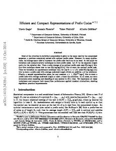
FIG. 2. 共a兲 Variation of thermal lens focal length and inverse 共Diopter兲 of that measured from the second principal plane of the thermal lens in the Nd:YAG rod as a function of the input pump power. 共b兲 Variation of the trace of the net roundtrip ABCD matrix of the resonator as a function of the pump power. It can be seen that the cavity is stable for a pump range of 90–910 W.
Particularly the pump power induced thermal lensing greatly influences the performance of the laser as its focal length varies inversely with the pump power and as a result of this, not only the laser mode size at various locations inside the resonator varies dynamically with the pump power but also the cavity becomes unstable as the pump power approaches some critical value. Hence, we analyzed the mode size variation inside the resonator as a function of the pump power by ABCD matrix analysis of the resonator incorporating the thermal lensing in the gain medium. The pumped portion of the Nd:YAG rod can be assumed as a thick lens with a transfer matrix19 given by M TL ⬅
冋
1 − l p/共2n0 f r,兲
l p/n0
− 1/f r,
1 − l p/共2n0 f r,兲
册
,
共1兲
where, l p = 60 mm is the pumped portion of the Nd:YAG rod near its center, n0共=1.8兲 is the refractive index of the Nd:YAG rod, and f r, are the thermal lens focal length for the tangential and azimuthal polarization, respectively. The variations of the thermal lens focal length 共f r兲 and its inverse 共Diopter兲 for the tangential polarization measured from the second principal plane of the pumped Nd:YAG rod as a function of the total diode power are shown in Fig. 2共a兲. It can be seen from Fig. 2共a兲 that the inverse of the thermal focal length increases linearly with the pump power as 1 / f r = 0.0114⫻ Pin关m−1兴, where Pin is the total emitted diode power in watts. For azimuthal polarization thermal focal
073104-4
Rev. Sci. Instrum. 81, 073104 共2010兲
Sharma et al.
length f can be calculated from the relation20 f / fr = 1.2. However, the results shown in Fig. 2 are under no-lasing condition. Under lasing condition the thermal loading at the Nd:YAG rod is reduced by a factor of ⬃1.25 and hence the Diopter would also reduce by the same factor.15 The transfer matrix for the thermally loaded Nd:YAG rod can be written as M rod ⬅ 关d兴关M TL兴关d兴,
共2兲
where the sections d are the nonpumped region at either end of the rod and each of ⬃20 mm thick. The effective length of the unpumped region is d = 20 mm/ n0. The net roundtrip ABCD matrix of the cavity can be written as M tot ⬅
冋 册
A B ⬅ 关M1兴 ⫻ 关l1兴 ⫻ 关M rod兴 ⫻ 关l2兴 ⫻ 关M3兴 C D ⫻ 关l2兴 ⫻ 关M rod兴关l1兴,
共3兲
where each component of the cavity is represented by its corresponding ABCD matrix. The matrices 关M1兴 and 关M3兴 are the transfer matrices for the mirrors M1 and M3, respectively. The matrices 关l1兴 and 关l2兴 represent the ray propagation matrices for the separation between M1 to Nd:YAG rod and Nd:YAG rod to the mirror M3, respectively, including the effective lengths of the intracavity components as shown in Fig. 1共a兲. The effective lengths l1 and l2 are estimated to be 8.1 and 9.2 cm, respectively. The measured variations of thermal focal length with the pump power are used to find the range of the pump power over which the cavity remains stable by using the resonator stability criteria − 1 ⬍ 共A + D兲/2 ⬍ 1.
共4兲
In Fig. 2共b兲 we plot the trace of the net round trip ABCD matrix as a function of the pump power for the tangential and azimuthal polarizations. It can be seen from Fig. 2共b兲 that the resonator is stable for a wide range of the pump power starting from 90 to 910 W. This shows that the resonator is well within the stable zone at the maximum pump power of 750 W. However, the mode-size inside resonator will vary dynamically with the pump power due to the thermal lensing. In Fig. 3共a兲 we show the estimated variation of the fundamental TEM00 mode size along the length of the resonator at the two extreme pump powers. Under low pump power 共100 W兲 the resonator is close to the boundary of the stability zone and the thermal lens focal length is just enough to compensate the divergence caused at the convex mirror M3 leading to a large and nearly constant TEM00 mode size along the length of the resonator. On the other hand at a pump power of 750 W, the thermal lens is very strong leading to a reduction of the mode size and focusing of the beam on M1. It can be seen from Fig. 3共a兲 that the mode size is relatively constant and larger on the right side of the Nd:YAG rod reducing the probability of damage of the LBO crystal under high power. In Fig. 3共b兲 the estimated variation of TEM00 mode radius at the middle of the Nd:YAG rod and that at the LBO crystal are shown as a function of the pump power. It can be seen that the mode radii at these two locations are nearly equal and vary slightly over the pump power range of 200– 750 W. This ensures that the threshold and the overlap efficiency of the pump beam and cavity mode would not vary
FIG. 3. 共a兲 The estimated variation of the fundamental TEM00 mode size along the length of the resonator at 100 and 750 W of pump power. 共b兲 Variation of the TEM00 mode radius at the middle of the Nd:YAG rod and at the LBO crystal as a function of the pump power.
dynamically over this range of the pump power and should lead to a linear slope efficiency curve. The TEM00 mode radius at the middle of the Nd:YAG rod and at the LBO crystal are estimated to be 330 and 310 m, respectively, at the maximum pump power. Finally, the generated green beam at 532 nm is taken out of the cavity through the mirror M3 and the average power was measured with the help of a power meter 共OPHIR, USA, model: LASERSTAR兲 with a measurement range of 0–250 W. To characterize the pulse shape the green pulses were detected with the help of a biplanar photodiode 共ITL Ltd., UK, model S13B7兲 with 0.1 ns rise time and displayed on a digital storage oscilloscope with 2 GHz bandwidth 共Lecroy, USA, model: Wave Runner 204 Mxi 2 GHz兲. III. PERFORMANCE OF THE LASER
First we operated the laser at the fundamental wavelength at 1064 nm by removing the LBO crystal and replacing the mirror M3 with a coupler mirror of 70% reflectivity at 1064 nm which was found optimum for maximum continuous wave 共cw兲 power generation. The slope efficiency curves at the fundamental wavelength are shown in Fig. 4. The solid points in the figure represent the cw power and the open circles are the average power under pulsed operation at 22 kHz as a function of the total emitted diode power. The laser had a threshold of ⬃140 W and output power increases
073104-5
Sharma et al.
Rev. Sci. Instrum. 81, 073104 共2010兲
FIG. 4. Measured slope efficiency curves at the fundamental wavelength at 1064 nm; solid points: cw operation, open points: at 22 kHz.
linearly with the pump power with 41% and 37% slope efficiency under cw and pulsed operation, respectively. The linear increase in output power versus pump power is in good agreement with the calculated cavity stability range. The maximum cw and average power obtained were 255 and 226 W, respectively, corresponding to 34% and 37% optical to optical conversion efficiency. We observed that operating the laser at a repetition rate below 22 kHz leads to Q-switching instability at the maximum pump power and subsequently rolling over of the output power. The performance of the laser in intracavity frequency doubled configuration is shown in Fig. 5. The solid circles are the average green power at 22 kHz and the open circles are the corresponding full width at half maximum 共FWHM兲 of the green pulse as a function of the total pump power. In intracavity frequency doubled configuration the threshold was also measured to be ⬃150 W. As the pump power was increased beyond 250 W the average green power increased linearly with the pump power. A maximum average power of 124.2 W at 532 nm was obtained at a total diode pumping power 738 W corresponding to 16.8% pump to green beam conversion efficiency. The total electrical power applied to the diodes was 1500 W and hence the overall wall plug efficiency was estimated to be 8.3%. The maximum average
FIG. 5. Measured variation of the average green power at 22 kHz repetition rate and the corresponding FWHM pulse duration as a function of the pump power.
FIG. 6. 共a兲 Variation of the average green power and the FWHM pulse width as a function of the repetition rate at the maximum pump power. 共b兲 Variation of the average green power and pulse width at the maximum pump power as the temperature of the LBO crystal is varied.
green power was 49.8% of the CW IR power obtained with the optimum coupling at the same amount of the pump power. The individual green pulse energy was estimated from the average power and the repetition rate and was found to be 5.64 mJ. It can be seen from Fig. 5 that the FWHM green pulse width decreased with the pump power and at 738 W of pump power the FWHM pulse width was measured to be 50 ns. This corresponds to a peak power of 112.7 kW. However, with further increase of the pump power the average green power was reduced slightly to 123.5 W and correspondingly the FWHM green pulse width was reduced to 48.5 ns. In Fig. 6共a兲 the average power and pulse width as function of the pulse repetition rate at the pump power of 738W are shown. It can be seen that the optimum repetition rate for the maximum average green power is 26 kHz at which the average green power was 132 W. However the pulse width increases linearly with the repetition rate. The shortest green pulse width of 50 ns was obtained at 22 kHz repetition rate. The repetition rate could not be reduced further due to the Q-switching instability. The performance of the laser is also strongly affected by the temperature of the LBO crystal since LBO has a temperature acceptance bandwidth of 8.4 ° C cm 共Ref. 20兲 and considering 1.8 cm length of the LBO crystal used in the system, the temperature acceptance bandwidth is estimated to be only 4.6 ° C. In Fig. 6共b兲 we plot the average green power and the pulse width as the LBO temperature was scanned from 15 to 32 ° C. Since
073104-6
Rev. Sci. Instrum. 81, 073104 共2010兲
Sharma et al.
FIG. 8. 共a兲 The stability of the maximum average green power over a time period of 2 h. 共b兲 Points are the measured spot radius after the focusing lens as a function of the distance from the second principal plane of the lens. Solid line is the fitting of the multimode beam propagation equation.
FIG. 7. 共a兲 A typical recorded pulse shape at the maximum pumping power. 共b兲 共up兲 The recorded Q-switch pulse train at 22 kHz, 共bottom兲 the histogram of the delay time in Q-switched pulses.
the LBO crystal was cut for type-II phase matching at 27 ° C, the maximum average green power of 128W was obtained at this temperature. There is another peak of 124 W at 24 ° C temperature. However the average green power falls rapidly as the LBO temperature deviates from the temperature range of 24– 27 ° C. It can be seen from Fig. 6共b兲 that the decrease in output power is much faster in the higher temperature side than that in the lower temperature region. We therefore operated the laser by keeping the LBO temperature fixed at 24.5 ° C to obtain minimum fluctuation in the output power due to the temperature variation in the cooling water from the chiller unit which supports ⫾0.2 ° C temperature stability. Further it can be seen that the green pulse width at 24.5 ° C 共50 ns兲 is slightly shorter than that at 27 ° C 共52.5 ns兲. A typical pulse shape recorded at the maximum pump power of 750 W is shown in Fig. 7共a兲. The FWHM pulse width was measured to be 48.5 ns with a rise and fall time of 26 and 75 ns, respectively. The amplitude of the Q-switched green pulses was highly stable with less than ⫾2% fluctuation in the peak power. The upper part of Fig. 7共b兲 shows the recorded pulse train at 22 kHz. In order to measure the jitter in time delay of the Q-switched pulses, the trigger was set with respect to the trigger pulses to the Q-switched driver
with a delay of 4.536 s. A typical histogram in the time delay of the Q-switched pulses is shown at the bottom of Fig. 7共b兲. The time jitter was estimated to be ⫾ 2.9 ns. The slope efficiency curve of the laser was highly repeatable as was confirmed by repeated operation of the laser. The output average green power was very stable throughout several hours of continuous operation. In Fig. 8 we plot the maximum average power of 124 W recorded for 2 h with the help of the power meter. The fluctuation in average green power was found to be only ⫾0.4 W. The excellent stability of the average power can be attributed to the provision of cooling to each of the component of the laser set up with precise maintenance of the temperature. The spatial profiles of the output green beam at different locations away from the laser were recorded with the help of a laser beam analyzer 共SPIRICON, USA, model no. LBA 100A兲. Two such beam profiles recorded near the laser and at 3 m distance from the laser are shown in Figs. 9共a兲 and 9共b兲, respectively. It can be seen that the green beam was circular in shape with less than 5% difference in spot size for the horizontal and vertical direction of the beam. It also can be noted that there is no significant deterioration in the spatial profile of the beam with the propagation distance only its width increases due to the divergence of the beam. We measured the beam propagation factor 共M 2-parameter兲 of the beam by using the standard beam propagation method. For this purpose the output beam was focused with the help of a plano-convex lens of 25 mm focal length and the spot radii of the pump beam at several locations after the focusing lens and around the focused position were estimated with the help of a knife edge with a 10% clip-level criterion.19 The variation of the greenbeam spot size was plotted as a function of distance from the secondary principal plane of the focusing lens, and the focused spot radius and M 2-parameter were estimated by leastsquares fitting of the usual multimode beam propagation law given by21
再 冋
w2共z兲 = w20 1 +
M 2 共z − z0兲 w20
册冎
,
共5兲
where wo is the radius at the waist, is the green beam wavelength, M 2 is the beam propagation factor, and zo is the
073104-7
Rev. Sci. Instrum. 81, 073104 共2010兲
Sharma et al.
from entering the Nd:YAG rod in our system, chances of color center formation through the third harmonic generation is also greatly reduced. The possibility of thermally induced fracture of the Nd:YAG rod is also avoided as the pump power per unit length of the Nd:YAG rod in our system is less than 150 W/cm which is considerably below the maximum pump power limit of ⬃2.5 kW/ cm permissible for Nd:YAG 共Ref. 20兲 before the fracture can occur. These allow us to estimate the life of the system as limited by the life of the laser diode. In conclusion, we have demonstrated a high power, compact, intracavity frequency-doubled Q-switched Nd:YAG laser suitable for pumping a Ti:sapphire amplifier or for micromachining applications. Our laser is capable of producing up to 124 W of power at 532 nm at 22 kHz repetition rate with 50 ns pulse duration. The long term average power stability is excellent with ⫾0.4 W of fluctuation in the output power. The amplitude and timing jitter of the pulses was measured to be ⫾2% and ⫾2.9 ns, respectively. The M 2-parameter was estimated to be 27. ACKNOWLEDGMENTS
Authors are thankful to Mr. P. Hedaoo of solid state laser division, RRCAT, for his technical help. J. Golden, Laser Focus World 28, 75 共1992兲. G. Hummelt, Laser Focus World 42, 77 共2006兲. 3 Y. Sugawara, Y. Uraoka, H. Yano, T. Hatayama, T. Fuyuki, and A. Mimura, Jpn. J. Appl. Phys., Part 2 46, L164 共2007兲. 4 S. Backus, J. Peatross, C. P. Huang, M. M. Murnane, and H. C. Kapteyn, Opt. Lett. 20, 2000 共1995兲. 5 E. Zeek, R. Bartels, M. M. Murnane, H. C. Kapteyn, S. Backus, and G. Vdovin, Opt. Lett. 25, 587 共2000兲. 6 H. Q. Li, H. B. Zhang, Z. Bao, J. Zhang, Z. P. Sun, Y. P. Kong, Y. Bi, X. C. Lin, A. Y. Yao, G. L. Wang, W. Hou, R. N. Li, D. F. Cui, and Z. Y. Xu, Opt. Commun. 232, 411 共2004兲. 7 L. McDonagh and R. Wallenstein, Opt. Lett. 32, 802 共2007兲. 8 C. Stolzenburg and A. Giesen, Opt. Lett. 32, 1123 共2007兲. 9 B. J. LeGarrec, G. J. Raze, P. Y. Thro, and M. Gilbert, Opt. Lett. 21, 1990 共1996兲. 10 J. J. Chang, E. P. Dragon, and I. L. Bass, 1998 OSA Technical Digests 共Optical Society of America, Washington, D.C., 1998兲, Vol. 6, pp. CPD22–CPD2-3. 11 Z. Ren, Z. Huang, S. Jia, Y. Ge, and J. Bai, Opt. Commun. 282, 263 共2009兲. 12 S. Konno, T. Kojima, S. Fujikawa, and K. Yasui, Opt. Lett. 25, 105 共2000兲. 13 Y. Bo, A. Geng, Y. Bi, Z. Sun, X. Yang, Q. Peng, H. Li, R. Li, D. Cui, and Z. Xu, Appl. Opt. 45, 2499 共2006兲. 14 X. K. Cheng, Q. J. Cui, Y. Zhou, Z. M. Wang, J. L. Xu, Y. Bo, Q. J. Peng, D. F. Cui, and Z. Y. Xu, Opt. Commun. 282, 4288 共2009兲. 15 J. Yi, H. J. Moon, and J. Lee, Appl. Opt. 43, 3732 共2004兲. 16 S. Christensen, H. C. Kapteyn, M. M. Murnane, and S. Backus, Rev. Sci. Instrum. 73, 1994 共2002兲. 17 S. Lee, Y. G. Kim, B. H. Cha, and Y. K. Kim, Opt. Laser Technol. 36, 265 共2004兲. 18 A. Geng, Y. Bo, Y. Bi, Z. Suna, X. Yang, Q. Penga, H. Lia, R. Lia, D. Cui, and Z. Xu, Opt. Lasers Eng. 44, 589 共2006兲. 19 N. Hodgson and H. Weber, Optical Resonators 共Springer-Verlag, Berlin, 1997兲. 20 W. Koechner, Solid State Laser Engineering, 6th ed. 共Springer, New York, 2006兲. 21 A. E. Siegman and S. W. Townsend, IEEE J. Quantum Electron. 29, 1212 共1993兲. 22 S. Backus, R. Bartels, S. Thompson, R. Dollinger, H. Kapteyn, and M. Murname, Opt. Lett. 26, 465 共2001兲. 1 2
FIG. 9. 共a兲 Recorded spatial profile of the green beam near the laser and 共b兲 recorded spatial profile of the green beam at 3 m distance away from laser. 共b兲 Results of M 2-parameter measurements: points are the measured spot radii after the focusing lens as a function of the distance from the second principal plane of the lens. Solid line is the fitting of the multimode beam propagation equation.
waist location from the focusing lens. The beam propagation factor and the focused spot radius estimated in this way were 27 and 100 m, respectively, at the maximum output power 关Fig. 9共c兲兴. The measured M 2-parameter is consistent with the mode radius analysis of the cavity as shown in Fig. 3共b兲. The average TEM00 mode radius at the Nd:YAG rod was estimated to be 330 m at the maximum pump power and the radius of the hard apertures placed on either side of the Nd:YAG rod was 1.9 mm. This corresponds to a maximum M 2-parameter of19 ⬃共1.9/ 0.33兲2 = 33. The measured M 2-parameter is smaller than this maximum value signifying that the role of thermal aberration and thermal birefringence on the beam quality was not significant. It is, hence, clear that the laser is suitable for pumping the tunable lasers such as Ti:sapphire or dye lasers which require M 2 ⬍ 35 for effective pumping.22 Finally, the lifetime of the laser system is limited by the lifetime of the pump laser diodes. The mechanism primarily responsible for the deterioration of the Nd:YAG rod is the formation of color centers due the absorption at the ultraviolet 共UV兲 wavelength which often occurs under the flash lamp pumping as the emission spectra of flash lamp has considerable UV contribution. Diode pumping eliminates the issue of color center formation as there is no UV radiation from the pump laser diodes. Further, since the green beam is blocked