http://www.ieee.org/publications_standards/publications/rights/index.html for more information ... balancing method for modular multilevel converter is presented.
This article has been accepted for publication in a future issue of this journal, but has not been fully edited. Content may change prior to final publication. Citation information: DOI 10.1109/TPEL.2014.2317705, IEEE Transactions on Power Electronics
> REPLACE THIS LINE WITH YOUR PAPER IDENTIFICATION NUMBER (DOUBLE-CLICK HERE TO EDIT)
REPLACE THIS LINE WITH YOUR PAPER IDENTIFICATION NUMBER (DOUBLE-CLICK HERE TO EDIT) < cascaded H-bridge (CHB) are the most preferred choices [1320]. For medium- voltage (2.3, 3.3 and 4.16kV) applications three-level neutral-point clamped is the suitable topology, but having the constrained of mass clamping and the voltage imbalance of dc-link capacitors in extending its use to higher voltage levels [14], [6-19]. For applications with voltage higher than 6 kV, cascaded H-bridge multilevel inverters are commonly used [15], [17], [20]. Isolated sources are required in this topology. To generate individual voltage sources, conventional method is to employ a multi-winding transformer with the same number of isolated secondary windings, which is huge and expensive. The modular multilevel converter (MMC) topology has recently drawn huge interest in high voltage applications [2125], [29-44]. It is first proposed by Marquardt and Lesnicar [22] and is regarded as one of the next-generation high voltage multilevel converters without line-frequency transformers [29]. The modularity, voltage scalability and common dc bus make MMC topology favourite for high voltage applications [31-40]. The first commercialized MMC-VSC-HVDC project is the Trans Bay Cable Project in the U.S.A., with 216 SMs for each arm. In addition, another MMC-VSC-HVDC project INELFE from France to Spain built by Siemens will be completed in 2013. It can transmit rated power 2×1000MW and has 401 voltage levels [30], [37]. Most of the advantages come from its scaled structure. Therefore, the voltage balancing of multiple floating dc capacitors of the SMs becomes a vital factor for the safe operation of MMC [24], [31]. There have been many research efforts made to explore the voltage balancing strategies based on level shifted PWM[31-35], phase-shifted PWM(PSPWM)[36-38], selective harmonic elimination(SHE)[39], and nearest level control(NLC) [40-44]. The high switching frequency of pulse width modulation is unsuitable for large numbers of SMs MMC. The switching losses are predominant in high switching frequency modulation. The voltage balancing algorithm based on phase shifted PWM requires individual SM balancing controller which is inappropriate for large numbers SMs MMC [36-38]. However, a large amount of switching angles in the SHE modulation is computed offline and stored in tables, so with large number of sub modules MMC based HVDC, the SHE method is complicated [40-44]. Due to the conceptual and implementation simplicity of the NLC method, the aim is to use it in converters with a high number of levels [43]. Few research papers are published on the NLC based voltage balancing algorithm of submodules capacitor voltages of MMC with the application to HVDC. One commonly used balancing approach is based on sorting of the voltages of the capacitors. Then the capacitors with the highest or lowest voltages are selected to be discharged or charged determined by the current direction [31-35], [40]. The predefined voltage deviation of the SM voltages can be set in [41]. The SM voltages fluctuations are limited by controlling the triggering frequency [42].There are number of stages of implementation of the balancing algorithm based on sorting. However, every stage of the balancing algorithm has not been clearly demonstrated in [40-44]. This paper presents simplified NLC method of voltage balancing based on sorting of the voltages of the SM capacitors, which can simplify and eliminate some of the
2
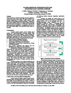
Fig. 1. (a) Three phase n – level MMC topology and (b) MMC sub – module.
S1 OFF OFF OFF ON
S2 ON OFF OFF OFF
TABLE I SWITCHING STATES OF A CELL Current Capacitor D1 D2 direction states OFF OFF iarm>0 Unchanged OFF ON iarm0 Charging OFF OFF iarm REPLACE THIS LINE WITH YOUR PAPER IDENTIFICATION NUMBER (DOUBLE-CLICK HERE TO EDIT)
REPLACE THIS LINE WITH YOUR PAPER IDENTIFICATION NUMBER (DOUBLE-CLICK HERE TO EDIT)
REPLACE THIS LINE WITH YOUR PAPER IDENTIFICATION NUMBER (DOUBLE-CLICK HERE TO EDIT)
REPLACE THIS LINE WITH YOUR PAPER IDENTIFICATION NUMBER (DOUBLE-CLICK HERE TO EDIT)
REPLACE THIS LINE WITH YOUR PAPER IDENTIFICATION NUMBER (DOUBLE-CLICK HERE TO EDIT)
REPLACE THIS LINE WITH YOUR PAPER IDENTIFICATION NUMBER (DOUBLE-CLICK HERE TO EDIT)
REPLACE THIS LINE WITH YOUR PAPER IDENTIFICATION NUMBER (DOUBLE-CLICK HERE TO EDIT)
REPLACE THIS LINE WITH YOUR PAPER IDENTIFICATION NUMBER (DOUBLE-CLICK HERE TO EDIT)
REPLACE THIS LINE WITH YOUR PAPER IDENTIFICATION NUMBER (DOUBLE-CLICK HERE TO EDIT)
REPLACE THIS LINE WITH YOUR PAPER IDENTIFICATION NUMBER (DOUBLE-CLICK HERE TO EDIT)
REPLACE THIS LINE WITH YOUR PAPER IDENTIFICATION NUMBER (DOUBLE-CLICK HERE TO EDIT)
REPLACE THIS LINE WITH YOUR PAPER IDENTIFICATION NUMBER (DOUBLE-CLICK HERE TO EDIT) < VIII. EXAMPLE FOR PROPOSED ALGORITHM IMPLEMENTATION The proposed algorithm can be implemented as illustrated in Fig. 17. An example of open loop MMC is considered for seven level output voltage. The proposed algorithm for single phase i. e. per leg is possible to implement using Texas DSP TMS320F2812 with 150 MHz operating frequency. This DSP has 12- bit ADC module with 16- channels. Out of 16 channels, 12 channels can be used to sense the SM capacitor voltages and 2 channels for upper and lower arm currents through the sensors. It has 5 input-output ports (GPIO) with 56 pins, out of which 24 pins can be used to trigger the IGBT switches. It has 128K× 16 memory with interfacing external memory of 1MB. This is sufficient to write the proposed algorithm. The conversion time of ADC in TMS320F2812 is 80 ns or 12.5MSPS (M samples per sec.). It can convert 14 signals within 1120ns. The sampling frequency can be increased more than 800KSPS, whereas required sampling frequency is 700 SPS (14×50). The switching frequency is considered 50Hz. The memory required will be around 65KB. The number of SMs and the IGBT switches required for three phases are 36 (12 SM per phase i.e. per leg×3) and 72(36×2) respectively. The experimental realization of this method for the three phases is possible using one master and two slave DSPs. The proposed algorithm eliminates the selection stage of redundancies of voltage levels. It does not require the individual sorting of the SM, and the identification of the SM can be carried out throughout the stages of the implementation of this method. This simplification and elimination of some of the stages may reduce the memory required and computational time to sixty percent as compared to the existing balancing algorithm methods. Nearest level control (NLC) method is basically suited for high number of sub modules of the output voltage. This is not convenient for the low number of levels and a low modulation index, since the total harmonic distortion of the output is very high [10]. Therefore the simplification, saving in memory and the computational time is more prominent to the high scale of the system.
the controllers. The combined simplification and reduction of processes at various stages of this method can lead to sixty percent saving in memory and the computational time of the processor at the implementation level compared to the existing balancing algorithms.
ACKNOWLEDGMENT The authors would like to thank the anonymous reviewers and the editors for their valuable advice and comments. REFERENCES [1]
[2]
[3]
[4]
[5]
[6]
[7]
[8]
[9]
[10]
IX. CONCLUSION This paper proposed simplified NLC voltage balancing method for MMCs. This algorithm reduces processes of the different stages from sorting of the sub modules to the selection of the number of sub modules for the triggering. The proposed method neither requires redundancy and the individual sorting of the sub modules nor the identification of individual sub module at the time of the triggering. The pictorial presentation of the simplified balancing algorithm also helps in enhancing the understanding of different stages of the algorithm. The comprehensive investigation of this method to one of the applications MMC-VSC-HVDC confirms the robustness under steady state as well as transient conditions. The sub module capacitor voltages can be well balanced for open as well as closed loop applications. The results show that the proposed method is significantly more accurate to the huge disturbances made at the various stages of
14
[11]
[12]
[13]
[14]
[15]
[16]
Jose Rodrigues, J. Lai., and FangZheng Feng, “Multilevel inverters: a survey of topologies controls and applications,” IEEE Trans.Ind. Eletron., vol. 49, no.4, pp. 724-738, Aug. 2002. Burhan Gultekin, and Muammer Ermis, “Cascaded Multilevel Converter-Based Transmission STATCOM: System Design Methodology and Development of a 12 kV + MVAr Power Stage,” IEEE Trans. Power Electron., vol.28, no.11, pp. 4930-4950, Nov. 2013. D. Peftitsis, G. Tolstoy, A. Antonopoulos, J. Robkowski, J. Lim, M. Bakowski, L. anguist, H. Nee, "High-Power Modular Multilevel Converters With SiC JFETs," IEEE Trans. Power Electron., vol.27, no.1, pp.28-36, Jan. 2012 C.Newton, and M. Summer, “Multilevel Converters: a real solution to medium/high voltage drives?,” IEE Power Eng. J. 1998, vol. 12, no.1, pp. 21-26, 1998. Jose Rodrigues, Steffen Bernet, Peter K. Stemer, and I. Lizama , “A survey on Neutral-Point-Clamped Inverters,” IEEE Trans.Ind. Eletron., vol. 57, no.7, pp. 2219-2230, July. 2010. X. Lie, L. Yongdong, Wang Kui,John C Clare, Patrick W. Wheeler, "Research on the Amplitude Coefficient for Multilevel Matrix Converter Space Vector Modulation,” IEEE Trans. Power Electron., vol.27, no.8, pp.3544-3556, Aug. 2012. P. Roshankumar, p. P. Rajeevan, K. Mathew, K. Gopakumar, Jose I. Leone, and Leopoldo G. Franquelo, "A Five-Level Inverter Topology with Single-DC Supply by Cascading a Flying Capacitor Inverter and an HBridge," IEEE Trans. Power Electron., vol.27, no.8, pp.3505-3512, Aug. 2012. S. Theilemans, A. Ruderman, B. Reznikov, and J. Melkebeek, “Improved Natural Balancing With Modified Phase- Shifted PWM for Single-Leg Five Level Flying Capacitor Converters,” IEEE Trans. Power Electron., vol.27, no.4, pp.1658-1667, April 2012. S. Kouro, M. Malinowski, K. Gopakumar, J. pou, L. G. Franquelo, B.Wu, J. Rodriguez, M. A. Perez, and J. I. Leon, “Recent advances and industrial applications of multilevel converters,” IEEE Trans. Ind. Electron., vol. 57, no. 8, pp. 2553–2580, Aug. 2010. J. Rodriguez, L. G. Franquelo, S. Kouro, J. I. Leon, R. Portillo, M. Prats and M. Perez, “Multilevel converters: An enabling technology for highpower applications,” Proceedings of the IEEE, Vol. 97, No. 11, pp. 1786–1817, Nov. 2009. J. Rodriguez, S. Bernet, B. Wu, J. O. Pontt, and S. Kouro, “Multilevel voltage-source-converter topologies for industrial medium-voltage drives,” IEEE Trans. Ind. Electron., vol. 54, no. 6, pp. 2930–2945, Dec. 2007. F. Peng, W. Qian, and D. Cao, “Recent advances in multilevel converter/inverter topologies and applications,” in Proc. Conf. Rec. IEEE IPEC, 2010, pp. 492–501. M. Malinowski, K. Gopakumar, J. Rodriguez, and M. perez, “A Survey on Cascaded Multilevel Inverters,” IEEE Trans. Ind. Electron., vol. 57, no. 7,pp. 2197–2206, July 2010. A.H. Bhat, and N. Langer, “Capacitor Voltage Balancing of Three-Phase Neutral-Point-Clamped Rectifier Using Modified Reference Vector,” IEEE Trans. Power Electron., vol.29, no.2, pp. 561-568, Feb. 2014. S. Gautam, and R. Gupta, “Switching Frequency Derivation for the Cascaded Multilevel Inverter Operating in Current Control Mode Using Multiband Hysteresis Modulation IEEE Trans. Power Electron., vol.29, no.3, pp. 1480-1489, March 2014. J. Chivite- Zabalza, P. Lzura-Moreno, D. Madariago, G. Calvo, and M. Angel-Rodriguez, “Voltage Balancing control in 3-Level Neutral-Point Clamped Inverters Using Triangular Carrier PWM Modulation for
0885-8993 (c) 2013 IEEE. Personal use is permitted, but republication/redistribution requires IEEE permission. See http://www.ieee.org/publications_standards/publications/rights/index.html for more information.
This article has been accepted for publication in a future issue of this journal, but has not been fully edited. Content may change prior to final publication. Citation information: DOI 10.1109/TPEL.2014.2317705, IEEE Transactions on Power Electronics
> REPLACE THIS LINE WITH YOUR PAPER IDENTIFICATION NUMBER (DOUBLE-CLICK HERE TO EDIT)