Mar 26, 2003 - Software performance modeling based on simulation models allows the ..... model elements, which is a subset of the Perl language [24].
A Simulation-based approach to Software Performance Modeling Simonetta Balsamo
Moreno Marzolla
Dipartimento di Informatica Universit`a Ca’ Foscari di Venezia via Torino 155, 30172 Mestre (VE), Italy e-mail: {balsamo|marzolla}@dsi.unive.it
March 26, 2003 Abstract Quantitative performance analysis of software systems should be integrated in the software development process from the early stages. Software performance modelling and analysis allows the software designer to address performance related issues such as the comparison of design alternatives. Software performance modeling based on simulation models allows the analyst to represent detailed characteristics of the system and makes it easier the integration of the performance model with the software specification model. We propose simulation-based performance modeling of software architectures specified in UML. We argue that simulation-based performance models are well suited for capturing the complex aspects and behaviors of software systems. We propose a methodology for deriving a simulation model from annotated UML software architectures. We introduce the annotation for some UML diagrams, i.e., Use Case, Activity and Deployment diagrams, to describe system performance parameters. Then we show how to derive a discrete-event simulation model by automatically extracting information from the UML diagrams. Simulation provides performance results that are reported into the UML diagrams as tagged values. The proposed methodology has been implemented into a prototype tool called SAPS (Software Architectures Performance Simulator). We describe an application example of the proposed methodology.
Keywords Software Performance Models, Discrete-Event Simulation, Unified Modeling Language (UML).
1
Introduction
Software performance is the process of predicting and evaluating whether the software system satisfies performance goals defined by the user [4]. Predicting the performances of a software system requires the availability of a suitable abstract model of the final software. Such model has to provide a suitable description of the run-time behavior of the software system, so that performance can be estimated. Performance evaluation, on the other hand, refers to the activity of measuring the performances of an actual implementation of a system. Measurement-based performance techniques requires the availability of a system implementation, while model-based techniques can be applied also at earlier stages of the software life-cycle. Early identification of unsatisfactory performance of Software Architecture (SA) can greatly reduce the cost of design change [22, 23]. The reason is that correcting a design flaw is more expensive the later the change is applied during the software development process. This is particularly true if the waterfall software development model is employed, as any change during the development process requires starting back from the beginning. However, this is still a relevant issue whenever a different software development process is used. Both quantitative and qualitative analysis can be performed at the software architectural design level. Qualitative analysis deals with functional properties of the software system such as for example deadlock-freedom or security. Qualitative analysis is carried out by deriving quantitative figures of merit, such as, for example, the execution profile of the software, memory or network utilization. We address performance analysis of software systems at the SA level based on performance models that can be either analytical or simulative models. Analytical performance models are mostly based on Queuing Networks [12], Stochastic Petri Nets [16] and Stochastic Process Algebra [10]. In this paper we consider the derivation of a simulation model from a SAspecification. We argue that simulation is well suited for capturing the complex aspects and behaviors of software systems, and thus concentrate on simulation-based performance models. We develop an algorithm for translating annotated UML specifications of software systems into simulation models. We consider SA expressed in term of Unified Modeling Language (UML) [17] Use Case, Activity and Deployment diagrams. The diagrams are annotated according to a subset of the UML Profile for Schedulability, Performance and Time Specification [18]
1
(referred as UML performance profile). Such annotations are used to add quantitative, performance-related parameters used to drive the simulation. The results are inserted into the original UML description of the SA. This paper is organized as follows. In section 2 we briefly review some of the main approaches recently proposed for software performance modeling. In Section 3 we illustrate the proposed methodology for generating simulation models from UML specification of SA. In Section 4 we apply the methodology to a simple case study, and conclusions and future works are discussed in Section 5. Details about SAPS (Software Architectures Performance Simulator), a tool we built to implement the described methodology, are summarized in Appendix A.
2
Modeling for Software performance evaluation
The Software Performance Engineering (SPE) methodology [22, 23] has been the first comprehensive approach to the integration of performance analysis into the software development process. It makes use of two models: the software execution model and the system model. The software execution model is expressed by Execution Graphs, representing the software execution behavior. The system model is based on queuing network models and represents the system platform, including hardware and software components. Various classes of performance models of software systems have been considered in the literature [4]: stochastic performance models based on Queuing Network models, Stochastic Timed Petri Nets and Stochastic Process Algebras [12, 16, 11, 10], and models based on simulation [1, 2, 3, 8]. Stochastic performance models can be handled using analytical methods or by simulation in order to evaluate performance indices such as resource utilization, system throughput and response time. Analytical solution techniques are usually more efficient and accurate than simulation, but can be applied only to models that satisfy a set of given constraints. Such constraints can be sometimes partially relaxed if approximate techniques are applied to analyze the model. However, some specific system characteristics are often hard or even impossible to be appropriately represented by analytical modeling that can be efficiently analyzed. Examples of such systems are systems with fork and join operations, simultaneous resource possession and asynchronous communication. Simulation, besides being a solution technique, is also a powerful modeling technique. Simulation performance models provide the advantage to be general and flexible in representing arbitrarily complex real-world systems, that can be too complex or even impossible to represent by analytical models. Simulation models can be developed by refering to two paradigms: process-oriented event-oriented [13]. In a processoriented simulation model, the system is represented as a set of interacting processes (or active entities). The processes reproduce the behavior of components of the real systems with an adequate level of detail, which depends on the goals of the simulation study and on the availability of detailed knowledge about how the real system works. In the event-oriented paradigm the system is modeled in term of events, which trigger changes of the simulation state. Thus, the modeler has to define the set of relevant events which may happen in the system, and for each event define how the simulated system reacts to that event (which means how the simulation state changes, and possibly the set of events which are generated and/or cancelled). Given both simulation paradigms have the same expressiveness, the choice of which one to adopt depends mainly on the nature of the system to be simulated and on other external factors (such as the availability of simulation tools or on the modeler’s preferences with respect to one specific paradigm). When the number of different event types is large, an event-oriented simulation model can be difficult to build and maintain. Moreover, if the real system cannot be easily described in term of events and state changes, an event-oriented simulation model can be difficult to derive. We consider UML representations of SA. The representation is made in term of Use Case, Activity and Deployment diagrams. As recognized in [20], Use Case diagrams provide information about the workloads driving the system, Activity diagrams show the internal dynamics of the system, and Deployment diagrams show the mapping between software entities (processing steps) and hardware entities (processors on which the software executes). These information can be combined together to form a performance model which includes both the software system and the hardware platform on which the system executes. We define a process-oriented simulation model of an UML software specification introducing an almost one-to-one correspondence between behaviors expressed in the UML model and the entities or processes in the simulation model. This correspondence between system and the model helps the feedback process to report simulation results back into the original SA. There are a few previous works dealing with simulation of UML specifications. Arief and Speirs [1, 2, 3] developed an automatic tool for deriving process-oriented simulation models from UML Class and Sequence diagrams. Their approach consists in transforming the UML diagrams into a simulation model described as an XML document. This model can then be translated into different kinds of simulation programs, even written in different languages, so decoupling the performance model from its actual implementation. De Miguel et al. [8] introduced UML extensions for the representation and automatic evaluation of temporal requirements and resource usage, particularly targeted at real-time systems. The extensions are expressed in term of stereotypes, tagged values and stereotyped constraints. These were introduced in a commercial UML CASE tool, which has been made able to generate OPNET simulation models starting from annotated UML diagrams.
2
Previous simulation-based performance modeling approaches for evaluation of UML SA were developed before the UML performance profile was defined. Thus, they introduced their special extensions to UML or introduced non-standard annotations to express quantitative information useful for deriving the model. In this paper we propose a methodology to derive a process-oriented simulation model from Use Case, Activity and Deployment diagrams, annotated according to a subset of the UML Performance Profile [18]. This annotation is used to automatically derive the processes and the parameters of the simulation model, which is eventually executed. Performance results obtained by simulation are inserted back into the original UML diagrams as tagged values, so providing feedback at the software architectural design level.
3
Description of the methodology
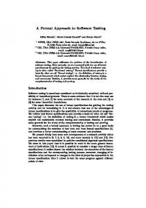
The proposed methodology of simulation-base software performance of SAis illustrated in the scheme presented in Fig. 1. We consider the SAspecification as a set of UML Use Case, Activity and Deployment diagrams. The diagrams are annotated with quantitative information expressed as tagged values, which are associated to each diagram. Then we derive a simulation model by defining its processes and parameters. The proposed approach translates Use Case diagrams into processes called workloads in the simulation model, Activity diagrams into processes called generic processing steps, and Deployment diagrams into processes representing computational resources (processors). We derive simulation model parameters from the tagged values extracted from the UML diagrams representing the SA. Once the process structure of the simulation model is defined, we build its implementation into a simulation program, which is eventually executed. Simulation provides the performance analysis results of the software system with a set of performance measures. Such results are inserted into the UML diagrams as tagged values and can be used to provide a feedback at the original SA design level. Then the modeling cycle from UML diagrams to simulation model and execution can be iterated to compare design alternatives and to identify a SA that satisfies given performance requirements.
UML Model Diagrams
Software Architecture
Simulation Model
Use Case
Workloads
Deployment
Resources
Activity
Steps
Tagged Values
Parameters
Processes
Simulation Parameters
Model Execution
Feedback
Figure 1: The proposed methodology for simulation modeling of software systems The proposed methodology has been implemented in the prototype simulation-based software performance evaluation tool SAPS, which processes an XMI [19] description of UML Use Case, Activity and Deployment diagrams. The UML SA has to be annotated using a subset of the UML Profile for Schedulability, Performance and Time Specification [18]. The objects of the process-oriented simulation model are derived by the analysis of the UML diagrams annotated with performance specification of the software system components. The simulation model is implemented in a simulation program, whose execution provides results for a set of performance indices. These include the mean response time associated with the execution of each Use Case and each Activity in the Activity diagrams. We also evaluate the utilization and throughput of the computational resources (processors) on which the Activities are executet. Fig. 2 illustrates the structure of the performance simulation model derived from the UML diagrams. The basic object of the simulation model is a PerformanceContext which represents the entire model. This object contains the other elements of the model, namely Workloads, Scenarios and processing Resources. Workloads represent requests to the system arriving from external users. The population of users may be infinite (open workload) or with limited, fixed size (closed workload). Closed workloads are characterized by the two following attributes: PApopulation the total number of users in the workload PAextDelay (of type PAPerfValue) the delay between the end of a scenario execution and the beginning of the next request
3
0..*
PerformanceContext
1..* 1..*
1..*
AbsPRhost PRhost
+PAutilization : mean +PAresponseTime : confInterval
1..*
Workload
PScenario
strategy
+PAschedPolicy : String +PArate : double
root
ClosedWorkload
1..*
+PApopulation : Integer +PAextDelay : PAperfValue
+PActxSwT : PAperfValue
steps
PRhost_impl
0..* +requestService()
AbsStep
OpenWorkload +PAoccurrence : RTarrivalPattern
+PAprob : double
PStep
+PArep : Integer
Pstep_fork
PRhost_FIFO
PRhost_PS
+PAdelay : PAperfValue PStep_join
+PAinterval : PAperfValue +PAdemand : PAperfValue +PArespTime : confInterval
PRhost_LIFO
+_successors
+_predecessors
Figure 2: Structure of the simulation performance model Open workloads are characterized by the following attribute: PAccurrence (of type RTarrivalPattern) the pattern of interarrival times of consecutive requests Each workload actually drives one or more scenarios. Each time a new user belonging to a workload requests service to the system, one of the scenarios associated with that workload is selected. Selection is done randomly, according to the probability associated to each scenario. A scenario is a set of abstract scenario steps, represented by the AbsStep class. All kinds of scenario steps are characterized by the following attributes: PAprob the probability to execute this step, in the case the predecessor step has multiple successors PArep the number of times this step has to be repeated PAdelay (of type PAPerfValue) an additional delay in the execution of this step, for example to model a user interaction PAinterval (of type PAPerfValue) the time between repetitions of this step, if it has to be repeated multiple times PAdemand (of type PAPerfValue) the processing demand of this step PArespTime the computed delay between the starting and the finishing time of this step. This value has type confInterval, which we define as the pair of the confidence interval bounds. Abstract scenario steps can either be composite steps (described by the PScenario class), or atomic steps of different kinds. Scenarios are collections of steps; exactly one of these steps is marked as the root step (starting step) of the scenario. Atomic steps can be of type PStep fork for nodes representing the creation of multiple execution threads, PStep join for nodes representing synchronization points between different threads, and PStep for normal atomic steps. Active resources (processors) are modeled as node instances in Deployment diagrams. Such nodes correspond to objects of type PRhost. The actual scheduling policy of the processor is implemented by an object derived from class PRhost impl, Each node instance can be tagged with the following attributes: PAschedPolicy (of type string; recognized values are “FIFO”, “LIFO” and “PS”) The scheduling policy of the processor, either first-come-first-served (FIFO), last-come-first-served (LIFO) or processor sharing (PS). PActxSwT (of type PAperfValue) the context switch time. PArate (of type real) the processing rate of the host, with respect to a reference processor. Thus, a PArate of 2.0 means that the host is twice as fast as the reference processor. PAthroughput The computed throughput of the resource. PAutilization The computed utilization of the resource.
4
UML elements Use Case Diagrams: Actors Use Cases Activity Diagrams: Activities Fork nodes Join nodes Deployment Diagrams: Node instances
Simulation Processes Types Workload PScenario PStep PStep fork PStep join PRhost
Table 1: Mapping between UML model elements and processes of the simulation model Note that the performance model shown in Fig. 2 is slightly different from the one described in the UML Performance Profile [18]. We choose a different structure for the processing steps and active resources class hierarchy in order to simplify the derivation of the simularion model. The UML Profile defines a PScenario class from which a PStep class is derived, thus every step is a scenario. This is because each step, at a deeper level of detail, could be modeled as a whole scenario, that is, a sequence of multiple substeps. We choose a different structure to model the PStep and PScenario hierarchy to keep atomic steps and scenarios as separate entities. We apply the Composite Pattern [9] to reflect the hierarchical nature of the processing steps. This choice makes the construction of the simulation model easier, because there are different kinds of step (e.g., PStep, PStep fork, PStep join) which are modeled as different simulation object types. The behavior of a fork step consists of activating all the successor steps concurrently. A join step waits for the completion of all predecessor steps before activating the successor. A normal step simulates execution according to the specified delays, and activates one of the successor steps. Finally, the behavior of a scenario is to activate its root step. Similarly, the class hierarchy representing active resources has been expanded. We apply the Command Pattern [9] to model hosts with different scheduling policies. The PRhost class represents actual host resources of the system. Class PRhost impl serves as a base class from which subclasses implementing the proper scheduling algorithm can be derived. Each operation on PRhost objects is implemented by simply calling the same operation on the associated PRhost impl object. Class AbsPRhost serves to group the common elements of the interface class PRhost and the implementation class PRhost impl. There is a direct mapping between the processes of the simulation model, which are instances of the classes of Fig. 2, and elements in the UML diagrams. The mapping is illustrated in Table 1. To summarize, the proposed approach to derive the simulation model to evaluate SA performance from UML Use Case, Activity and Use Case diagrams is defined as in Fig. 3. The algorithm creates a new process for each relevant element in the UML model. The first step is identifying the Actors in Use Case diagrams. Each actor is translated into an OpenWorkload or ClosedWorkload simulation process, depending on its stereotype. Then, each Use Case associated with the Actor is examined and translated into a PScenario simulation process. To define the content (sequence of steps) of the scenario, the Activity Diagram associated with the Use Case is examined. All the activities are translated into the appropriate kind of step (that is, PStep, PStep fork or PStep join) depending on the type of the UML element. Finally, each node instance in the Deployment Diagrams is translated into a simulation process of the appropriate type, depending on the scheduling policy specified by the user in the tagged values.
4
Case Study
In this section we illustrate with an application example of the proposed methodology described in the previous section. The example is very similar to the one appearing in Sec. 8 of [18]. It involves a web-based video streaming application. We assume a constant population of N users. Each user selects a video to view using a web browser and the browser contacts the remote web server for the video to be sent back through the Internet. The video server triggers the activation of a video player on the workstation of the user before sending the stream of frames. The UML Use Case, Deployment and Activity diagrams are depicted in Fig. 4. Model elements are tagged according to the notation described in Section 3. Note that an analytical model of the system of Fig. 4 can not be easily evaluated due to the fork/join component in the Activity diagram. The simulation model derived from the SA consists of several active components (processes) arranged according to the structure depicted in Fig. 5. The actor is represented by an object of type ClosedWorkload, which handles the fixed population of users. The Use Case is mapped into an object of type PScenario and has a queue which collects users according to their arrival order. There is one simulation process for each node in the Activity diagram. Nodes can be Activity nodes,
5
{Parses Use Case Diagrams} for all Use Case Diagram U do for all Actor a ∈ U do if a is tagged as OpenWorkload then Make new OpenWorkload object else if a is tagged as ClosedWorkload then Make new ClosedWorkload object end if for all Use Case u associated with a do Sc ←Make new PScenario object A ←Activity Diagram associated with u {Parses Activity Diagram} for all Activity s in A do if s is an atomic step then Add new PStep to Sc else if a is a fork step then Add new PStep fork to Sc else if a is a join step then Add new PStep join to Sc end if Add a to Sc end for end for end for end for {Parses Resources} for all Deployment Diagram D do for all Node instance n ∈ D do p ←New PRhost if n is tagged with LIFO scheduling policy then p0 ←New PRhost LIFO else if n is tagget with PS scheduling policy then p0 ←New PRhost PS else p0 ←New PRhost FIFO end if Link p with p0 end for end for Figure 3: Creation of the simulation model
6
Request Video
User
PApopulation = 10 PAextDelay = ["assm", "dist", ["exponential", 1.0/50.0]]
(a) Use Case Diagram
(b) Deployment Diagram
(c) Request Video Activities
Figure 4: UML representation of a Web video application. which are modeled by processes of type PStep, or fork and join nodes which are modeled by processes of type PStep fork and PStep join, respectively. Node instances from the Deployment Diagrams are mapped into simulation processes of type PRhost. Note that, in order to avoid visual cluttering, in Fig. 5 we omit the association between activity steps and the processors (computational resources) on which they execute. For simplicity, we also did not show the actual scheduling implementation objects associated with each processor. We observe that the structure of the simulation model derived by the proposed algorithm is very similar to that of the UML model. The mapping between the two models is almost immediate, which allows the simulation to be easily and efficiently built. This also make it is extremely easy to associate the performance results to the original UML elements. A numerical example of the performance results, computed as steady-state average delays are reported in Table 2. The
7
Figure 5: Object diagram of the simulation model of the SA of the web video software system. results are obtained by setting a population of N = 20 users and the other model parameters are set from the tagged values as shown in Fig. 4. The computed simulation results are intervals obtained at 90% confidence level. Such results are inserted into the original UML diagrams as values of the PArespTime tag associated with each Activity, and the PAutilization and PAthroughput tags associated with each Node instance in the Deployment Diagram. The software designer can now explore different situations by repeating the modeling and performance evaluation process with different tag values.
Scenario Request Video Resource ClientWorkstation WebServerNode VideoServerNode Internet
Average delay (seconds) [65.3993, 65.7069]
Utilization [0.183559, 0.183619] [0.0152827, 0.0153439] [0.0432813, 0.0433357] [0.764314, 0.764321]
Throughput (requests/sec) [0.0611551, 0.0611941] [0.0152827, 0.0153439] [0.030573, 0.0305853] [1.5285, 1.52852]
Table 2: Simulation results for the web video application of Fig. 4.
5 Conclusions and Open Problems We have proposed a simulation-based software performance modeling approach for software architectures specified with UML. Performance parameters are introduced in the specification model with an annotation which is a subset of the one defined in the UML Performance Profile [18]. The proposed algorithm derives the process-oriented simulation model from Use Case, Activity and Deployment UML diagrams. The performance results estimated by the execution of the simulation model are eventually inserted into the original UML diagrams as tagged values, so providing a feedback to the software designer. The methodology has been implemented in a prototype performance modeling tool called SAPS. We have shown an application example of the software performance modeling methodology to derive quantitative measures from an UML software specification. The proposed approach has been defined to evaluate software performances at the SA design level. We plan to extend this approach to further steps of the software development process, by considering also other types of UML diagrams. In particular,
8
Sequence diagrams could be used in place of Activity diagrams to describe the dynamic behavior of the system [18]. The use of Deployment diagrams will be extended to include passive resource modeling, as well as active resources. Further research will be devoted to a more complete set of performance measures.
Appendix A
SAPS Tool Description
The steps of the proposed methodology are implemented into a simulation tool called SAPS. As concerns the annotation of UML diagrams, the UML Performance Profile suggests the use of TVL (Tag Value Language) to describe values of tags applied to model elements, which is a subset of the Perl language [24]. We use the freely available Perl interpreter library [6] to evaluate tag values, so taking advantage of the full Perl language. Note that both the UML Performance Profile and SAPS do not strictly depend on the specific language used to express annotations. The PAperfValue and RTarrivalPattern data types are expressed according to the following BNF notation, which is a simplified version of the annotations defined in the UML Performance Profile: < PAperfValue > < PDFstring >
:=
0 0
:=
0 0
[ “assm”|“pred”|“msrd”, “dist”, < PDFstring >0 ]0 [ < constantPDF > | < uniformPDF > |
< exponentialPDF > | < normalPDF >0 ]0 < constantPDF >
:=
“constant”, < real >
< uniformPDF >
:=
“uniform”, < real >, < real >
< exponentialPDF >
:=
“exponential”, < real >, < real >
< normalPDF >
:=
“normal”, < real >, < real >
< RTarrivalPattern >
:=
0 0
< bounded >
:=
“bounded”, < integer >, < integer >
< bursty >
:=
“bursty”, < PDFstring >, < integer >
< unbounded >
:=
“unbounded”, < PDFstring >
[ < bounded > | < unbounded > | < bursty >0 ]0
SAPS parses an XMI description of UML diagrams, annotated as described above. The UML model is translated into a C++ discrete-event simulation program according to the proposed methodology. SAPS includes a general purpose discrete-event simulation library providing roughly the same functionality of the Simulation class of the S IMULA language [7], namely pseudo-parallel process execution using coroutines and Sequencing Set scheduling facilities. We developed the simulation library for several reasons, mainly code portability, availability of compilers and the necessity to use a freely available C library for parsing XML documents [15]. The simulation library includes random number generators and some statistical functions. Random variates of various distributions are generated using the uniform random number generator described in [14]. The library provides basic estimation functions, e.g. mean, variance and confidence interval. Since we consider steady-state simulation, we discard an appropriate initial portion of the observations to remove the initialization bias. The mean is computed using the method of independent replications [5]. The simulation stops when the relative width of the computed confidence intervals is smaller than a given threshold. Both the confidence level and the threshold can be defined by the user. If they are not provided, we assume default values of 90% confidence level and 5% threshold. Each UML Actor is mapped into an appropriate Workload object, that can be an open or closed workload, depending on the stereotype which is applied to the UML element. Workloads are active objects in the simulation, which simply perform an endless loop in which they select and activate a Use Case, whose behavior is activating the root step of its associated Activity diagram. Each Activity in the Activity diagram is translated into the corresponding kind of AbsStep object. These objects simulate execution of the corresponding step or scenario according to the structure of the diagram and the value of the associated tags. Finally, each Node instance is mapped into a PRhost object with an associated PRhost impl implementation scheduler. When an activity requests service, it calls the requestService() method of the processor on which the activity runs. At the end of the simulation, the computed average response time of each AbsStep object (that is, a step or scenario) is inserted into the original UML diagram the PArespTime tag. Also the computed utilization and throughput of each processor is inserted into the UML Deployment diagrams as PAutilization and PAthroughput tags respectively. The SAPS tool is used as described in the modeling cycle illustrated in Fig. 1. Namely, the software designer defines an UML SA with ArgoUML and specifies model parameters as tagged values associated with UML elements. Then, the user optionally selects parameters such as simulation length or confidence interval width, and runs the simulation. When the simulation finishes, the results are automatically inserted into the UML diagrams. At this point the software designer accesses the simulation
9
performance results by opening the ArgoUML project file to access the results, and then possibly iterates the performance evaluation analysis by providing a new set of parameters in the UML model tags.
References [1] L. B. Arief and N. A. Speirs. Automatic generation of distributed system simulations from UML. In Proceedings of ESM ’99, 13th European Simulation Multiconference, pages 85–91, Warsaw, Poland, June 1999. [2] L. B. Arief and N. A. Speirs. Using SimML to bridge the transformation from UML to simulation. In Proc. of One Day Workshop on Software Performance and Prediction extracted from Design, Heriot-Watt University, Edinburgh, Scotland, November 25 1999. [3] L. B. Arief and N. A. Speirs. A UML tool for an automatic generation of simulation programs. In Proceedings of WOSP 2000 [21], pages 71–76. [4] S. Balsamo, A. Di Marco, P. Inverardi, and M. Simeoni. Software performance: state of the art and perspectives. Technical Report MIUR SAHARA Project TR SAH/04, December 2002. [5] Jerry Banks, editor. Handbook of Simulation. Wiley–Interscience, 1998. [6] Comprehensive Perl Archive Network (CPAN). http://www.cpan.org/. [7] Ole-Johan Dahl and Kristen Nygaard. SIMULA–an ALGOL-based simulation language. Communications of the ACM, 9(9):671–678, September 1966. [8] M. De Miguel, T. Lambolais, M. Hannouz, S. Betg´e-Brezetz, and S. Piekarec. UML extensions for the specifications and evaluation of latency constraints in architectural models. In Proceedings of WOSP 2000 [21], pages 83–88. [9] E. Gamma, R. Helm, R. Johnson, and J. Vlissides. Design Patterns: Elements of reusable Object-Oriented programming. Addison–Wesley, 1995. [10] Holger Hermanns, Ulrich Herzog, and Joost-Pieter Katoen. Process algebra for performance evaluation. Theoretical Computer Science, 274(1-2):43–87, 2002. [11] K. Kant. Introduction to Computer System Performance Evaluation. McGraw-Hill, Int. Editions, 1992. [12] L. Kleinrock. Queueing Systems, volume 1. J. Wiley, 1975. [13] Averill M. Law and W. David Kelton. Simulation Modeling and Analysis. McGraw–Hill, 3rd edition, 2000. [14] Pierre L’Ecuyer. Good parameters and implementations for combined multiple resursive random number generators. Operations Research, 47:159–164, 1999. [15] libxml: the XML C library for Gnome. Available at http://xmlsoft.org/. [16] M. Ajmone Marsan, G. Balbo, G. Conte, S. Donatelli, and G. Franceschinis. Modeling with Generalized Stochastic Petri Nets. J. Wiley, 1995. [17] Object Management Group (OMG). Unified modeling language (UML), version 1.4, September 2001. [18] Object Management Group (OMG). UML profile for schedulability, performance and time specification. Final Adopted Specification ptc/02-03-02, OMG, March 2002. [19] Object Management Group (OMG). XML Metadata Interchange (XMI) specification, version 1.2, January 2002. [20] R. J. Pooley and P. J. B. King. The Unified Modeling Language and performance engineering. In IEE Proceedings – Software, volume 146, pages 2–10, February 1999. [21] ACM Proceedings of WOSP 2000, 2nd International Workshop on Software and Performance, Ottawa, Canada, September 17–20 2000. [22] C. U. Smith. Performance Engineering of Software Systems. Addison-Wesley, 1990. [23] Connie U. Smith and Lloyd Williams. Performance Solutions: A Practical Guide to Creating Responsive, Scalable Software. Addison–Wesley, 2002. [24] Larry Wall, Tom Christiansen, and Jon Orwan. Programming Perl. O’Reilly & Associates, third edition, July 2000.
10