We show how typi- cal Middle-size robots with features like omni-drives and omni-directional .... Gazebo follows an approach on the middle ground between fully ...
A Simulation Environment for Middle-size Robots with Multi-level Abstraction⋆ Daniel Beck, Alexander Ferrein, and Gerhard Lakemeyer Knowledge-based Systems Group Computer Science Department RWTH Aachen Aachen, Germany {dbeck, ferrein, gerhard}@cs.rwth-aachen.de
Abstract. Larger fields in the Middle-size league as well as the effort to build mixed teams from different universities require a simulation environment which is capable to physically correctly simulate the robots and the environment. A standardized simulation environment has not yet been proposed for this league. In this paper we present our simulation environment, which is based on the Gazebo system. We show how typical Middle-size robots with features like omni-drives and omni-directional cameras can be modeled with relative ease. In particular, the control software for the real robots can be used with few changes, thus facilitating the transfer of results obtained in simulation back to the robots. We address some technical issues such as adapting time-triggered events in the robot control software to the simulation, and we introduce the concept of multi-level abstractions. The latter allows switching between faithful but computionally expensive sensor models and abstract but cheap approximations. These abstractions are needed especially when simulating whole teams of robots.
1
Introduction
In several RoboCup leagues proposals for simulation environments have been made (e.g. [5–7]). In the Middle-size league (MSL) there exist a variety of different simulators. Nearly every team has implemented a simulation environment which is tailored to specific needs like the hardware platform in use, and the research focus of the particular team. Some teams are interested in high-level simulations, for instance to deploy reinforcement learning, others simulate lowlevel algorithms for localization, or vision, and others try to model prototypes for hardware developments in a simulation environment. Because of this diversity, the re-use of a simulator by another team is difficult, if not impossible. ⋆
This work was partially supported by the German Science Foundation (DFG) in the Priority Program 1125, Cooperating Teams of Mobile Robots in Dynamic Environments and by the NRW Ministry of Education and Research (MSWF). Further support by the Bonn-Aachen International Center for Information Technology (BIT) is gratefully acknowledged.
As the soccer fields in the MSL become larger (the size doubled compared to last year’s competition) only very few teams can afford a full-size soccer field to test the robots and their behaviors. The number of players allowed per team was increased to six. To build and maintain a whole team of six robots will be hard for many teams. Further, the Technical Committee fosters the building of mixed teams and the team strategy of the mixed teams must be coordinated. A commonly accepted simulation environment which is able to satisfy the different needs of the teams and which is moreover able to simulate two teams of robots in a physical correct way will be of much more importance in the MSL in the coming years. In this paper we propose a simulation environment for soccer robots in the Middle-size league. We envision a Middle-size simulation league where two teams can play simulated matches against each other with minimal changes to the original control software yielding realistic results. Our proposal founds on the 3D rigid physics simulation Gazebo. We briefly introduce the Gazebo framework and then show how on top of this a full simulation environment for the MSL can be developed, which allows for realistic simulations of low-level algorithms working on sensor data including image synthesis up to the strategy of a whole team of six robots. We discuss models for some of the most important sensors and actuators. The key to simulate whole games is the concept of multi-level abstraction, which we present at the end of the paper. The rest of the paper is organized as follows. Section 2 introduces Gazebo and Player. Section 3 discusses other approaches to the simulator problem for RoboCup and argues why Gazebo is a good choice for our purposes. In Section 4 we sketch our models for realistic omni-drives, omni-directional cameras with realistic distorted images, and directed cameras on pan/tilt units. We also briefly address the accuracy of the simulation by comparing a differential drive in simulations with real data. In Section 5 we address the problem of how the robot control software must be adapted to fit to the simulation wrt. timing issues and introduce the concept of multi-level abstractions. Then we conclude.
2
Gazebo and Player
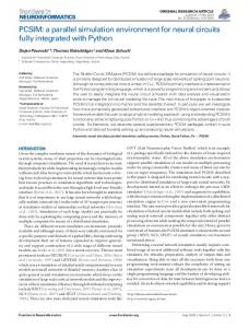
Our simulation environment relies on the simulator Gazebo [1] and the robot control server Player [2]. Gazebo is a 3D simulator and makes use of the freely available and constantly improving physics engine ODE [?]. Since Gazebo employs OpenGL for rendering of the simulated camera images sophisticated algorithms for rendering photo-realistic images might be integrated into Gazebo. Furthermore, Gazebo features a nice graphical user interface that allows to monitor the simulated world, inspect the current sensor readings and send commands to the actuators of the robots. In Gazebo the simulation world, that is the 3D environment as well as the robots, is defined by means of a configuration file. Fig. 1 shows an example for the definition of one of our robots including a SICK laser range finder and a Sony camera on a pan-tilt unit. The positions of the devices are defined relative to the
bot1 0 0 0 25 laser1 -0.131 0 0.101 20 front1 0.1 0 0.325 Fig. 1. Excerpt from a world-file demonstrating how a robot is made up of three modules (the chassis, a laser range finder, and a pan-tilt-zoom camera.
robot’s coordinate system. Further parameters, e.g. the update frequencies of the laser scanner, can be specified. The model file in Fig. 1 relates physical models to each other. The physical models are defined as C++ classes that describe the geometrical structure of the device, how sensor data are generated, and how data and commands are exchanged with external applications. A model can describe a physical object that possibly integrates a sensor or actuator. Since ODE is a rigid body simulator models have to be described in terms of those (which is sufficient for a robot simulator). Rigid bodies can be connected to each other by means of several different types of joints. Actuators are modeled by applying forces on those joints. The Player network protocol [2] allows to exchange data and commands with a robot and is designed in a device-independent fashion. The communication between server and clients makes use of several task-specific interfaces (e.g. a camera interface to retrieve images). Device-dependent drivers are required for the communication with the hardware. Libraries, implementing the Player network protocol, exist for various programming languages. Since Player only defines the protocol and does not impose a certain architecture on the control software it can be easily integrated into an existing control software.
3
Why Gazebo is a Good Choice for the MSL
In the last decades a large number of robot simulators have been developed. Due to the considerable variation of application requirements of those simulators not all of these approaches are equally well-suited for providing a close-to-reality runtime environment for the control software. In the following we focus on a couple of selected characteristics of robot simulators and discuss related approaches under this aspect. A (computer) simulation always constitutes an abstracted view of the system that is to be examined. Relating to robot simulators the level of abstraction
ranges from representing a robot as a dot in a two-dimensional world (e.g. MROSE [4]) to simulators that attempt to physically correctly simulate the robot, its sensors, and all other objects in the simulation world. The latter kind of simulators are so-called high-fidelity simulators. Since we intend to use the simulator not only as a test-bed for the high-level decision making components we require a high-fidelity simulator. Simulators that have an integrated physics engine compute the motion dynamics of the robot according to the physical properties of the models (e.g. its mass, the friction coefficients of surfaces, etc.). This means that the simulation model, the mathematical model on basis of which the progression of the simulation is computed, are the laws of physics. Other robot simulators rely on kinematic (e.g. SimRobot [3]) or probabilistic motion models (e.g. M-ROSE [4]). The probabilistic motion models are computed from observations that describe how the position of the robot changes as a reaction to certain movement commands. Most modern robot simulators are based on physics engines (e.g. USARSim [5], ¨ UberSim [6], Webots [7]) since they deliver very realistic results without the need for extensive evaluation of the real robots in order to get a proper kinematic or probabilistic motion model. Another characteristic of a robot simulator is how the control software is coupled with the simulator. A very tight coupling is realized by SimRobot [3] which directly integrates the controller for the robot into one binary with the simulator itself. Most simulators provide interfaces that allow external applications to communicate with the simulated robots. Still, the control software might be integrated into the simulation loop as it is the case for the Simulation league RoboCup Soccer Simulator [?]. It is based on the Spark simulator framework [8] which integrate the Spades middle-ware [9]. Spades implements the so-called software-in-the-loop architecture. Its approach is to notify the control software when the simulation of a frame is finished, give it some time to do its computation, and then proceed with the simulation. This does not correspond to the situation in the real world where the environment changes while the control software is deciding what action to take next. Only loosely coupling the control software and the simulator corresponds to the realistic model since the simulator progresses without taking care of the control software—it is the task of the control software to keep up with the simulation speed. Some robot simulators are specialized on certain types of robots and/or scenarios and cannot (easily) be extended (e.g. the UCHILSIM simulator [10] only simulates the Sony Aibo robots and the RoboCup Soccer Simulator is specialized on simulating soccer games). For the configurable, multi-purpose simulators it is interesting in which way robots and other objects in the simulation world can be ¨ defined. In Ubersim, for instance, the objects in the simulated world are made up of basic primitives which can be combined and parameterized in a configuration file. Gazebo on the other hand requires to actually program most parts of the models. The advantage of the first approach is that the simulated world can be changed without the need to recompile, but the latter approach admits the user the chance to bail out the full expressiveness of a programming language for the description of the models.
Currently, there are several robot simulator that meet our requirements. In ¨ particular, these are USARsim, Webots, Ubersim, and Gazebo. USARsim is the simulator for the RoboCupRescue simulation league and is based on the Unreal Tournament game engine. Consequently, it features a high-quality rendering engine, a high overall stability, an integrated physics engine, and several tools for comfortably editing the simulated worlds. USARsim also supports Player. ¨ Ubersim was primarily developed as a simulator for the small-size league and was later enhanced to serve as a simulator for vision-centric robots. It has been successfully used to simulate a self-stabilizing two-wheeled robot but it seems not to be actively worked on at the moment. Webots is a commercial product and contains besides the actual simulator a large library of hardware components for robots that can be integrated into the simulation and allows for certain types of robots to directly transfer software developed within the simulation to the robot. In the end we opted for Gazebo because it is available under an open source license, comes with a viable documentation, is actively maintained, and supports the open network protocol Player. Also, Gazebo proved to be capable of simulating complex robots in realistic environments (cf. [?]).
4
Physical Modeling
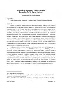
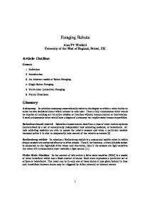
Gazebo comes with a set of standard robot and sensor models. Robots like the RWI B21, the Pioneer 2AT, or sensors like the SICK LMS 200 laser range finder are already modeled. Gazebo follows an approach on the middle ground between fully scripted and fully implemented physical models. The geometry, mass distribution, friction, etc. of parts have to be programmed. From the basic models the robot’s appearance and the position of devices are defined using an XML script as presented in Fig. 1. Important for the MSL is to have basic models of commonly used actuators and sensors. Most importantly for the MSL is a model for an omni-drive and for an omni-directional camera. Unfortunately, such models are not built-in models of Gazebo, and especially these models are problematic in many other simulation environments. However, these models are not too difficult to model in Gazebo and we developed models for an omni-directional and a differential drive as well as for omni-directional cameras. These models can be used as a prototype implementation and easily adopted to other robot platforms. Fig. 2(a) shows the models of different drives. The left image shows two of our differential drive robots on an MSL soccer field; the right image shows our model of a prototypical omni-directional drive. The model of the omni-wheel constitutes a realistic description of the actual mechanics of the wheel, i.e. the small rollers are connected to the center wheel by means of rotational joints. Tricks like omitting the definition of the rollers and setting the friction coefficient of the center wheel to zero along the direction of the axle are not needed. Fig. 2(b) shows images from our directed camera (left side) and our omnidirectional camera (right side). The implementation of this model is based on
(a) Models of a soccer-field and robots with differential drive (left) and a prototype for an omni-drive robot platform (right).
(b) Simulated camera images of a directed and an omni-directional camera processed by the vision modules Fig. 2. Our Gazebo models for MSL robots.
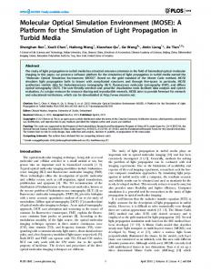
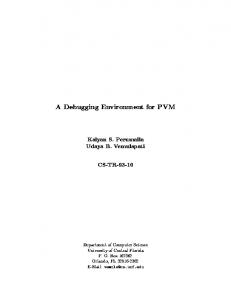
the cube-mapping technique. Images of the environment are mapped to the faces of a cube; this texture can then be applied to the surface of a three-dimensional object—in our case a mesh object resembling the surface of a hyperbolic mirror. The realism of the synthesized images was further improved by integrating focal depth and shadow mapping (which can be observed in Fig. 2(a)). Since the simulation is based on a physics engine (ODE in our case) information about the dimensions and mass of the robot and its components have to be defined in the model. The more precise this information is the more realistic the results of the simulation will be. In general, it is quite challenging to exhaustively measure the degree of realism of a simulation of a robot because it requires the knowledge of ground truth in the real world in order to compare virtual and real robots. To acquire some means about accuracy and quality of our simulation framework, we conducted several experiments comparing the simulation models with the real behavior of the robot components. An example for one of those experiments can be seen in Fig. 3. It compares the acceleration behavior of the the real robot (Fig. 3, left) and the simulated robot (Fig. 3, right) given a certain target velocity (the red line). Since, in our case, the parameters of the PID controller implemented in the real motor controller DSP were unknown we conducted the tests for several different parameter sets. Regarding the quality of the simulated camera images (Fig. 2(b)) one first has to note that the markings of the ball stem from the vision algorithms which
Fig. 3. These graphs compare how the real and the simulated robot react to a linear increase in the target velocity (the red lines). On the left, the actual velocities of the real robot are shown for several runs. The actual velocities of the simulated robot are shown for different parameter sets for the PID controller.
we use on our real robots. The vision software was used without any changes. The simulated camera images obviously differ from real camera images but the vision recognition modules yielded satisfactory result. Finally, we tested the model of the SICK LD scanner. Gaussian noise is added to the exact distances such that the variance of the real device is met. The results of our localization and collision avoidance algorithm which rely on the range data showed a good approximation of reality.
5
Connecting the Control Software
In this section we describe which changes are necessary to connect a control software to the simulator and show that the adaptations are only limited to the low-level hardware drivers and timing components. In other words, a control software designed for a real robot can be refitted quite easily (Sect. 5.1). Further, in Sect. 5.2, we introduce a concept that allows to simulate the robots on more abstract levels which is desirable for multi-robot scenarios, e.g. a robot soccer game. For reasons of space we can only roughly outline the concept and not give any technical details of how this concept manifests in the implementation of the robot’s model. The architecture of our simulation environment follows the client/server concept. The simulation server runs the simulator and a separate instance of the Player server for each simulated robot. Each robot is controlled by an instance of the control software which can be spread over several machines; these are called the simulation clients. The general approach to integrate a Player client into an existing control software is to replace those parts of the system that are directly communicating with the robot’s hardware by the appropriate functions provided by the client library to access the respective component in the simulation, i.e. instead of requesting a camera image from the frame-grabber an image is obtained from the simulated camera. Before data can be exchanged with the simulation server a connection to the Player server has to be established which is usually done once during the initialization of the control software.
Our control software consists of numerous, asynchronously running modules communicating by means of a central blackboard. Those modules are embedded into a hierarchy that defines which modules directly exchange data and/or commands with one another. The lowest level of this hierarchy comprises the modules that interact with the hardware components of the robot. According to the approach proposed above we implemented new modules that communicate with the simulation and these are started instead of the real drivers. Replacing the low-level modules was sufficient to provide the control software with the necessary input data and the capability to send commands to the actuators (the images in Fig. 2(b) for instance are the output of the unchanged image processing routines). In our experiments it showed that opening one connection to the Player server for each module separately produced too much overhead and slowed down the simulation server noticeably. The solution is to open only one single connection to the simulation server which is then shared by all modules. We remark that connecting a monolithic control software to the Player server would have been even easier. 5.1
Synchronization
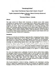
Low-level as well as high-level components of a control software often use time and duration as part of their decision-making. Thus, time may have a major influence on the behavior of the robot. As a consequence, all timing related issues have to be handled w.r.t. the simulation-time instead of the real-time clock. This guarantees that temporal intervals are computed correctly. In a robot control software it is quite usual that certain events are triggered at regular intervals like grabbing a camera image and processing it. When a simulated robot is controlled, the problem arises that the simulation may progress at a non-uniform speed. This means that the interval timer which triggers the event cannot be set to a constant interval time. Instead the interval time has to be adapted to the current simulation speed. Reasons for the changing simulation speed are that in certain situations more computations are necessary to determine the successor state. For example, collisions of objects lead to such situations. The step-time is the time by which the simulation is progressed in each step. The ratio of the step time and the time it took to compute the last step is called the instantaneous simulation speed. As it can be seen in Fig. 4 the instantaneous simulation speed varies considerably and, consequently, it is impossible to obtain an accurate estimate of when the simulation-time will have increased by a certain amount of time. As a remedy we compute the estimate for the current simulation speed as the average over a history of fixed length of past instantaneous simulation speed values. In Fig. 4 the results of averaging over histories of different length are depicted. The estimated simulation speed is used to predict how long it takes to progress the simulation by a certain amount of time. Interval timers triggering certain event are then set accordingly. As expected the accuracy of the prediction decreases with an increasing length of the interval. We tested intervals of lengths between 10 msec and
Fig. 4. The graph shows the erratic characteristics of the instantaneous simulation speed (the red line) and the results of smoothing over 5, 10, 20, and 50 consecutive instantaneous simulation speed values.
500 msec. For intervals between 10 msec and 100 msec (which are the most commonly used intervals in our control software) the average prediction error lies within a range of less than two percent of the interval length; for intervals between 150 msec and 500 msec the average prediction error is still less than four percent. In order to gain a resolution of the clock higher than the step-time of the simulation we extrapolate the simulation time between two consecutive updates taking into account the current estimate of the simulation speed. Since in our control software there exists a single component that handles all timing related issues it was sufficient to exchange the low-level modules and to extend this time component such that it can provide the current simulation time and estimate the current simulation speed—the rest of the control software runs unchanged in the simulation environment. 5.2
Multi-Level Abstraction
Simulating the robots on a device level, i.e. simulating the output of the real sensors, allows the complete control software (except those components that communicate with the hardware) to be tested with a simulated robot. Although this definitely is one of the objectives for the simulation environment, it would be helpful, in certain situations, to also have a more abstract simulation of the robots, for example, if a high-level concept should to be evaluated but lower level components providing appropriate input data are not (yet) available. Usually, the way how the processing of sensor data is managed in a robot control software is the following. In a first step the sensor readings are aggregated, then relayed to one or several other components which take this data as input. The output of those modules might be forwarded to other components that do some further processing, and so on. This is exactly where the concept of multi-level abstraction applies. Instead of simulating sensor readings the input data of higher-level components is directly provided by the simulation (cf. Fig. 5(a)). What kind of information that is depends on the component and on what kind of input data is provided by lowerlevel components, respectively.
Drive Commands
Simulation
...or...
...or...
Data & Commands
Positional Data
Collision Avoidance
Localization
Motor Commands
Distances
Motor-Module
Laser-Module
Data Sensor
P1
P2
P3
Command
(a)
(b)
Fig. 5. (a) General idea of the concept of Multi-level Abstraction. Example: Suppose the sensor is a pan-tilt camera. Then P1 aggregates images from the camera and translates pan-tilt commands into the camera’s protocol. P2 is a vision recognition module and provides information about the detected objects to P3. P2 might receive commands like “Search for object X in the images!” or “Look at world point (x, y, z)!”. (b) In this example it is not reasonable to shift the functionality of the collision avoidance module to the server side in a higher level of abstraction since the computational complexity is not reduced despite of complete world knowledge.
By selecting a higher abstraction level for a sensor it becomes unnecessary to run those components that normally generate the input data for a certain highlevel component on basis of the sensor readings obtained from sensors since it is now simulated directly. This implies that high-level components can be tested and evaluated completely independent of the lower-level components. More precisely, the error-rate of the input data for a high-level component can be controlled directly. Usually, the input data of a high-level module is quite easy to compute given the fact that ground truth is known in the simulated world. The error-rate is then adjusted by adding noise to the absolutely correct data. A sideeffect of not simulating raw sensor readings is that the computational complexity can be reduced because simulating realistic sensor readings and processing those data on the client-side, both rather expensive, can be omitted in a high-level simulation. High-level sensors not only have to generate high-level information. Also, they have to accept commands issued by the high-level component which they directly provide input data to. This is because those commands possibly lead to a change in the simulated world that affects the provided information, e.g. the visibility of an object depends on the viewing direction of the camera and thus a high-level pan-tilt camera has to accept pan-tilt-commands. A complete example is given in Fig. 5(a). It has to be noted that it is not reasonable for every component to shift its functionality to the simulator in a high-level simulation. For instance, suppose the laser distance readings are processed by the localization component as well as by the collision-avoidance component as it is depicted in Fig. 5(b). A high-level simulation of the laser the output of the localization component can be provided directly but it is of no advantage to also simulate the workings of the collisionavoidance component. This is because the knowledge about ground truth in the simulated world does not reduce the computational complexity for the problem of collision-avoidance—the same algorithms as in the control software would have to be implemented for a simulation of the collision-avoidance component.
The concept of multi-level abstraction as we implemented it opens up new possibilities for testing high-level components in a realistic environment. It has to be noted that even in a high-level simulation all the advantages of the integrated physics engine are still desirable (e.g. correct motion dynamics, collision detection, etc.). The reduction of the computational complexity comes in handy if the simulator or the control software have to be started on a slower machine or a greater number of robots is to be simulated simultaneously. Especially the rendering of simulated camera images is very expensive and consequently doing a high-level simulation of the cameras leads to a considerable increase of the average simulation speed. Our implementation allows to select the abstraction level for every instance of a model separately and thus simulations with mixed levels of abstraction are possible.
6
Conclusion
The simulation environment we presented allows to realistically simulate robots on a device level. We successfully modeled omni-directional drives and integrated new rendering techniques into Gazebo that allow to simulate images of omnidirectional cameras on the one hand, and on the other hand increase the realism of the rendered images by adding shadows and focal depth to the images. Thus, all components typically built into robots of the middle-size league can be simulated. We presented the concept of multi-level abstraction. The idea is to simulate the robotic system on different abstraction levels. If the task is to develop lowlevel modules like navigation or localization algorithms, a low level of abstraction is needed. In that case one simulates the robotic system in great detail with the down-side of a more complex simulation (for example, when images have to be rendered). Here, the simulation environment gives precious information how the implemented algorithm work in a near-to-reality environment. Since only minimal and especially no structural changes are necessary to make an existing control software control a simulated instead of a real robot, the transfer of software developed with the simulation to a real robot is facilitated. Due to the standardized network protocol Gazebo can be exchanged by the 2D simulator Stage [2] effortlessly, where, for instance, learning tasks with more than real-time can be performed. Following our vision that the simulation framework presented in this paper could serve as a standard simulation environment for the MSL where whole matches are simulated, one clearly needs a higher level of abstraction. Simulating on a behavior level, raw images do not have to be synthesized. In a real game, usually, this information is not logged either. In the future we want to extend our framework with an automatic referee similar to the Simulation league. This sets the prerequisite to simulate whole games in a realistic way and with this establishing a Middle-size Simulation league, so to say. This should not be seen as a supplement for real games. It should give a means to increase the quality of the games at competitions. On
the other hand, with such a standardized simulator the quality of research in the field of RoboCup is increased as the simulator can provide (simulated) ground truth data. Regarding Gazebo as the underlying engine we remark that we do not claim that this is the only possible choice for an MSL simulator. Gazebo just turned out to be very well suited to tackle this problem. As another, more technical issue for future work, one weakness of the simulator must be addressed. For very large multi-robot simulations the (single) server/(multiple) clients architecture of the simulation environment does not scale too well. The problem lies in the fact that the simulation at present cannot be distributed. Therefore we intend to enhance the simulator such that it allows distributed simulations. In a first step it is planned to integrate distributed rendering into the simulator since image synthesis is one of the most expensive parts of the simulation. While we focused on the MSL in this paper, it was shown that soccer and service robotics as well as service robotics and Gazebo can be married successfully as the example of [?,?] shows. Thus, the scope of our framework ranges much beyond Middle-size league soccer playing.
References 1. Scrapper, C., Balakirsky, S., Messina, E.: MOAST and USARSim: a combined framework for the development and testing of autonomous systems. In: Unmanned Systems Technology VIII; Proc. SPIE-06. (2006) ¨ 2. Browning, B., Tryzelaar, E.: Ubersim: a multi-robot simulator for robot soccer. In: Proc. AAMAS ’03, ACM Press (2003) 948–949 3. Michel, O.: Cyberbotics ltd. webots: Professional mobile robot simulation. http://www.cyberbotics.com/publications/ars.pdf (2006) 4. Koenig, N., Howard, A.: Design and use paradigms for gazebo, an open-source multi-robot simulator. In: Proc. ICRA-04. (2004) 2149– 2154 5. Gerkey, B., Vaughan, R., Howard, A.: The player/stage project: Tools for multirobot and distributed sensor systems. In: Proc. ICAR-03. (2003) 317–323 6. www.ode.org (2007) last visited Feb. 7. Buck, S., Beetz, M., Schmitt, T.: M-ROSE: A multi robot simulation environment for learning cooperative behavior. In: Distributed Autonomous Robotic Systems. LNAI. Springer (2002) 8. Siems, U., Herwig, C., R¨ ofer, T.: SimRobot, ein System zur Simulation sensorbest¨ uckter Agenten in einer dreidimensionalen Umwelt. Number 1/94 in ZKW Bericht. Zentrum f¨ ur Kognitionswissenschaften. Universit¨ at Bremen (1994) 9. sserver.sourceforge.net (2007) last visited Feb. 10. Obst, O., Rollmann, M.: Spark - a generic simulator for physical multi-agent simulations. In: Proc. MATES-04. (2004) 243–257 11. Riley, P.F., Riley, G.F.: Next generation modeling iii - agents: Spades — a distributed agent simulation environment with software-in-the-loop execution. In: Proc. WSC-’03. (2003) 817–825 12. Zagal, J.C., del Solar, J.R.: Uchilsim: A dynamically and visually realistic simulator for the robocup four legged league. In: RoboCup 2004: Robot Soccer World Cup VIII. Volume 3276 of LNCS., Springer (2005) 34–45 13. M¨ uller, A., Beetz, M.: Designing and implementing a plan library for a simulated household robot. In: Proc. CogRob-06, AAAI-06 (2006) 119–128 14. Schiffer, S., Ferrein, A., Lakemeyer, G.: Football is coming home. In: Proceedings of the International Symposium on Practical Congnitive Robots and Agents. (2006)