From R. Zoebel and D. Moeller, eds., 1998, Proceedings of the 12th European Simulation Multiconference, University of Manchester, p.437-442
A SIMULATION TESTBED FOR BIOLOGICALLY INSPIRED ROBOTS AND THEIR CONTROLLERS Jesse A. Reichler1 and Fred Delcomyn2 1Department of Computer Science 2Department of Entomology 2Program in Neuroscience University of Illinois Urbana, IL 61801, USA E-mail:
[email protected],
[email protected]
KEYWORDS AI, Robotics, Dynamics, Biologically inspired, Control systems, Interfaces
ABSTRACT This paper introduces a dynamics simulator designed to aid the development of control algorithms for biologically inspired robots. We describe the simulator and a two-tier framework for control code interfacing that allows control code to be written in a standard object-oriented language (C++), but encapsulates such code to produce modular, reusable, distributed controllers with parameterizable inputoutput transmission properties such as delay, sampling rate, and noise.
INTRODUCTION A key issue in the field of robotics and artificial intelligence is how to achieve adaptive and flexible behavior in a manmade system such as a walking robot. Although a number of walking robots have been constructed (Brooks 1989; Wettergreen et al. 1993), adaptable and flexible control of them is still difficult. The current generation of walking robots can handle obstacles, but cannot easily move quickly over rough terrain or right themselves if they fall. Because many insects exhibit adaptable and flexible locomotion, some robots have been designed with the structural features of insects, on the grounds that such features will confer to robots the same flexibility of locomotor performance exhibited by the animal system after which the robot is modeled (Brooks 1986; Beer et al. 1997; Delcomyn 1997). Insects are eminently suitable models because they are physiologically relatively simple and their walking is inherently stable. Furthermore, the physical features of insect legs and joints can readily be determined, then modeled in hardware (Kram et al. 1997). Despite the intuitive appeal of this approach, the design of appropriate controllers for these robots has been difficult. Traditional control system engineering has proved unsatisfactory because of the large numbers of sensory and
motor signals and because of the complicated nonlinearities involved (Franklin et al. 1990). A recent alternative has been to use parallel distributed control models (e.g. Brooks 1986; Beer 1990), an approach that has had some success. In addition to the theoretical control issues, there are significant practical impediments to developing controllers for biologically inspired robots. One such impediment is the need to have a physical robot interfaced to the control code as it is being developed. As the robot and its control system become more complex, the construction of, maintenance of, and interface to a physical robot may come to consume significant time. Even when a suitable robot is available, hardware constraints and communication bottlenecks can impede the design of control code. A second impediment is the requirement that control algorithms perform in real-time throughout the development cycle. Simulation can sometimes offer a way around these impediments. In the remainder of this paper, we describe a dynamics simulator designed specifically to facilitate the rapid development and testing of control algorithms for biologically inspired robots. We show how the application of common object-oriented design principles to the issue of control code interfacing induces a natural decomposition of the control problem. It separates the design of control code from the specific instantiation of robots and their controllers, and provides a bridge between the two that supports the modular reuse and parameterization of control algorithms.
THE SIMULATION SYSTEM Our system simulates the dynamics, sensors, and actuators associated with articulated robots or animals. In this paper, we focus on its use in the development of controllers for biologically inspired legged robots, but it is also possible to simulate traditional robotic devices such as robot arms, or to investigate strategies of physiological motor control by simulating the body, musculature, and sense organs of an animal. The simulator is a dynamics simulator, meaning that objects have mass and inertia and behave appropriately when
subjected to disturbance forces, as opposed to a kinematic simulator, which models movements but not forces. The entire system consists of approximately 500k of C++ source code. It has been compiled on a variety of Unix platforms, and uses the X windows and OpenGL graphics libraries. The physical parameters of the robot to be simulated -- the size, construction, and placement of its legs and body, and the number, location, and properties of sensors and actuators (including physiologically based models in biological simulations) are specified in configuration files accessed by the simulation during initialization. In this way, the system can be configured to emulate a wide variety of articulated robots or arthropod animals.
Freeman and Orin 1991), which is itself based on a number of previous approaches (e.g. Featherstone 1987; Lilly 1993; Shih and Ravani 1987). The DTS approach models the contact between the chains (legs) and the body (hip) as rigid, but models ground contact using a penalty based spring-damper method (Figure 2). Penalty-based methods have received much criticism due to the stiffness of the differential equations and their inherent instability and inexactness (Baraff 1992), but can be implemented easily and efficiently, and can qualitatively simulate a variety of surface types. We are currently exploring more robust contact resolution routines that would enable us to simulate grasping, inter-limb contact, and physical interactions between robots (see for example Mirtich 1996).
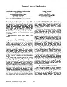
User control code is written in standard C++, but interfaces with the simulation in such a way that users need not have knowledge of the underlying simulation code. Multiple controllers can be attached to a single robot, and various properties of the controller input and output variables can be parameterized to simulate transmission delays, sampling rates, and noise. Figure 1 shows the simulation running a typical experiment.
Figure 2. Conceptualization of the DTS approach to simulation of a multi-legged robot. Each leg is attached rigidly to the base, and each joint is considered to be powered. Ground contact is modeled using a penalty based spring and damper method.
Figure 1. Typical graphical display during simulation run, showing a generic body with six articulated legs. The inset at the top left is an interaction panel that allows the user to adjust specific parameters during the simulation. The other two insets are windows that show stick figure top and side views of the simulated object and the forces felt during ground contact.
Dynamics We have used dynamics algorithms derived from the decoupled tree-structure approach (DTS) (Freeman 1989;
Our implementation of DTS supports a mobile base with any number of attached open serial chains composed of links with revolute joints. Links are described using modified Denavit-Hartenberg parameters (Lilly 1993). Although the DTS approach is amenable to arbitrarily branching chains and generalized joints (see for example McMillan et al. 1996), we have restricted ourselves to serial (non-branching) chains and revolute joints.
Sensors and Actuators Sensors can be attached at arbitrary points on a robot, providing information about the movements of the body parts and the forces imposed on them. When the simulation is configured to emulate an insect, we simulate insect sense organs (Delcomyn et al. 1996) and sensory neurons that provide information about cuticular (exoskeletal) strain (Delcomyn 1991; Cocatre-Zilgien and Delcomyn 1995). Vision is simulated through the use of a simple video camera model.
Movement may be effected either via torques applied directly to the joints or, when simulating an animal, through simulated muscles. For such simulations, we currently use a muscle model based on work by Hill (1975; see also Krylow et al. 1995). The model incorporates serial and parallel elastic components, shows fatigability, and is controlled by incoming nerve impulses, like biological muscle. Additional actuator models, including pneumatic cylinder models (Cocatre-Zilgien et al. 1996) and more biologically inspired models such as the muscle-like rubbertuator device used to control some existing anthropomorphic robot arms (Van Der Smagt et al. 1996) might also be simulated. The simulator has been specifically designed to allow incorporation of arbitrary sensor and actuator models.
Configuration Language One key to the flexibility of our simulation system is the use of a simple configuration language that employs a uniform hierarchical format for specifying the physical assembly of objects and the conditions of an experiment. This includes the specifications of sensors, actuators, and controllers, as well as the environment, the graphical displays, the data files to read or write, and the kinds of interactions allowed on-line during the simulation. The configuration language is modeled after C++ syntax, is modular, easy to read, and usable by non-programmers. An important feature of the configuration language is the use of a generalized referencing scheme that allows any variable or parameter of an object to be specified as the target or source of subsequent operation. All objects (robots, sensors, controllers, etc.) are named in configuration files. Reference to a state variable or parameter of an object is accomplished via the standard C/C++ language convention of listing a hierarchical trail of parent objects followed by the name of the parameter to access (e.g., “simplebot.leftfrontleg.knee.Joint_Angle”). The generalized referencing scheme provides a single, uniform interface to the multitude of internal simulation parameters. All displays, interactive panels, and control code structures use this scheme to specify their inputs and outputs. The user can, for example, specify that the current angle of a specific revolute joint (on a specific leg of a specific robot) should be saved periodically to a data file, or be made available for on-line manipulation by the user, or be provided as an input variable of a specific controller. In addition to standard graphical displays, movies and raw data files can be recorded for later analysis. Movies are recorded in a custom format that preserves all internal simulation data rather than simply saving graphic images of the simulation. This allows the user to manipulate camera views during playback and to examine disturbances and forces as they originally occurred. State information may also be saved at designated intervals in a file format easily
readable by Matlab, Mathematica, or other data analysis programs.
INTERFACING WITH THE SIMULATOR The issue of interfacing control code is often considered of secondary importance in robotic dynamics simulations. For projects where the primary objective is accurately reproducing a complex physical plant, this may be justified. In such projects, control code development is either not part of the simulation effort at all, or is considered a custom application to be developed upon completion of the dynamics simulation. We have channeled our efforts in a different direction. We have focused on the construction of a tool for designing and testing complex, non-traditional robotic control algorithms. From this standpoint, having a quantitatively precise model of a physical robot is less important than being able rapidly to interface complex distributed control algorithms, and to explore the performance features of these algorithms. The contribution of this work is not in the development of new dynamics algorithms or sensor and actuator models, but rather in the application of a few basic ideas from object oriented programming to the interface of user-written control code in a robotic simulation system. We have used a two-tier approach to control code interfacing that allows control code to be written in a standard high level language (C++), but encapsulates such code to produce modular, reusable, parameterizable, distributed controllers that can be developed without knowledge of the underlying simulation code. The first tier consists of "controller stubs," which form the bridge between the configuration language and external control code algorithms. Controller stubs are attached to robots from within configuration files and specify the input and output variables to which controllers have access. The second tier consists of a set of extensible C++ classes that support communication and coordination between the simulation and user-derived control structures, and are responsible for simulating transmission properties such as delays and noise. These built-in classes provide the standard foundation for all control code development.
Controller Stubs Controllers observe sensors and drive actuators. A single robot may have many controllers, and may possess hierarchical controllers that govern other controllers. Controllers are "attached" to robots within configuration files, using "controller stubs" that serve as a bridge between the simulation and user-written control code. A controller stub specifies the name of the control class, the inputs and outputs that the controller has access to, and the transmission properties to be simulated. As configuration files are parsed, controller stubs instruct the program to locate the appropriate user-written C++ class and instantiate a new copy of the control code with its own independent
state variables. The separation of controller code and controller stubs means that control libraries can be developed independently of the assembly of robots, and then parameterized and plugged into robots as desired. It is the use of controller stubs, as a layer of abstraction between the simulation and user-written code, that allows us to perform simple but powerful manipulations of controller input and output data as it passes between the simulation and any control algorithm. A controller stub can specify sampling rates that govern how often the controller is invoked and how often each of the input variables (sensors) are updated. Transmission delays for both input and output variables can instruct the simulation to buffer and pipeline signals in order to simulate delays that might be present in a physical system. A noise model can introduce uniform or gaussian noise into input and output variables. The manipulation of sampling rates, transmission delays, and noise can be used to reproduce a more realistic (and hence more difficult) control problem, and can be useful in testing the robustness of a control algorithm. The code below shows a simple controller stub that might be included inside a robot configuration file. It instructs the simulation to locate the user-written control class “SimplePD,” in this case a traditional proportionalderivative controller, and instantiate (attach) a controller that observes the current angle and desired angle of a specific joint, and that drives the joint torque. The controller is set to be invoked at every (simulated) millisecond, but the joint angle input variable is sampled every two milliseconds, suffers a four millisecond delay, and is corrupted with white noise on the order of a tenth of a radian. Note that the controller stub does not require any information about how the control algorithm functions; it simply specifies the input and output variables and their properties. CONTROLLER jointbrain { class="SimplePD"; // user-written controller class SimplePD samplerate=0.001; // control code is invoked every ms INPUTVAR angle { feature=robot1.leg1.segment1.Joint_Angle; samplerate=0.002; // angle sampled every other ms delay=0.004; // but value delivered is 4ms old noisemodel=uniform; noiseamplitute=0.1; } INPUTVAR goal feature=robot1.leg1.segment1.Joint_GoalAngle; OUTPUTVAR torque feature=robot1.leg1.segment1.Joint_Torque; }
C++ Controller Classes Control algorithms are written by users as C++ classes that are derived from a built-in "parent" control class provided
with the simulation. This derivation simply requires the declaration of any local state variables, and the definition of a small set of procedures (virtual functions) that the user must provide. These include a procedure for the registration (or publishing) of parameters and input and output variables, an initialization procedure, and a procedure for actually processing the inputs and driving the outputs. Optional procedures can be provided to save and load state information for a learning controller. User-written control classes can be compiled independently of the simulation, and are linked into the simulation automatically. It is easy to modify existing control algorithms, which may have been written for another application, to conform to our control class format. Requiring control algorithms to be derived from the parent control class ensures that all user-written control algorithms conform to a standard interfacing format, and can be attached to robots in a plug-and-play fashion. A benefit of the two-tier approach is that once a control algorithm has been written, it exists as a kind of black box that can be (multiply) instantiated on arbitrarily configured robots, with widely varying simulated operating parameters but without modification of the algorithm code itself. The use of controller stubs and our generalized referencing scheme, which allows any variable of any object in the simulation to be referred to by name, also means that control classes can make internal parameters accessible to the rest of the simulation for on-line manipulation or display.
DISCUSSION Simulation has historically been a valuable tool in the design of robotic controllers. It has allowed researchers to explore the stability of control algorithms, automate training of adaptable control algorithms, and perform tests that might damage a physical robot or injure a human operator. For the control systems engineer interested in nontraditional robotics, simulation offers additional advantages by providing a platform for experimenting with robots that cannot economically be built or acquired and for evaluating control algorithms independently of real-time implementation issues like execution speed or the impact of transmission delays or sampling rates. For example, in designing a controller to recover from missteps, an engineer might like to be able to test basic algorithms without worrying about execution speed, and then, given a candidate algorithm, explore implementation details like how fast and accurately the algorithm would have to execute in order to be effective. Simulation can address questions like how well a control algorithm will perform if the transmission delay of a specific sensor is doubled, if its sampling rate is halved, or if noise is introduced into a transmission line. Interestingly, these are the kinds of questions that are crucial in building real robots, but can be
the most difficult to answer in hardware because of its fixed characteristics. We have described a robotic simulation system that we believe makes it possible to study such issues with very little overhead, and that provides support for biologically inspired and nontraditional actuators and sensors. In this paper, we have focused on two aspects of the system that we believe may be of potential interest to robotics and control systems researchers: First, a simple configuration language and generalized referencing scheme that allows control structures and user interface elements to communicate flexibly with each other and access arbitrary state information. Second, a control code interfacing scheme that facilitates the integration of modular, distributed control code written in C++, and that supports the simulation of signal properties such as sampling rates, transmission delays, and signal noise.
Brooks, R.A. 1989. "A Robot that Walks: Emergent Behaviors from a Carefully Evolved Network." Neural Computation 1: 253-262. Cocatre-Zilgien, J. and F. Delcomyn. 1995. "Computer Simulation of Campaniform Sensilla in an Insect Leg." In Proceedings of the 4th International Congress of Neuroethology. M. Burrows, T. Matheson, P.L. Newland, and H. Schuppe, eds. Georg Thieme Verlag, Stuttgart. 448. Cocatre-Zilgien, J.H., F. Delcomyn and J.M. Hart. 1996. “Performance of a Muscle-like ‘Leaky’ Pneumatic Actuator Powered by Modulated Air Pulses.” Journal of Robotic Systems 13: 379-390. Delcomyn, F. 1991. “Activity and Directional Sensitivity of Leg Campaniform Sensilla in a Stick Insect.” Journal of Comparative Physiology A 168: 113-119.
We note that while the core articulated-body dynamics algorithms employed by the simulation are well founded, the contact force routines that we currently use are penaltybased methods, and can only be said to provide gross approximations of physical contacts. The same must be said of our sensor and actuator models. We therefore consider the simulator to be useful in producing qualitative models rather than quantitative ones.
Delcomyn, F. 1997. “Insect Models for Robotics.” In Encyclopedia of Neuroscience, 2nd edition (CD-ROM), G. Adelman and B. Smith, eds. Elsevier, Amsterdam.
In summary, our work has been motivated by a desire to reduce the overhead often incurred in robotic control systems research. Specifically, we have attempted to address the needs of researchers interested in nontraditional sensors and actuators, and non-traditional control algorithms. Our strategy has been simple: Allow the actual control code to be written using a standard objected oriented language, but provide a bridge between the control code and the dynamics simulator. It is this “bridge,” embodied by the configuration language, that makes it easy to reconfigure robots, parameterize controller instantiations, and extend the simulation.
Featherstone, R. 1987. Robot Dynamics Algorithms. Kluwer Academic Publishers, Boston.
REFERENCES Baraff, D. 1992. "Dynamic Simulation of Non-Penetrating Rigid Bodies." Ph.D. Thesis, Cornell University. Beer, R.D. 1990. Intelligence as Adaptive Behavior. An Experiment in Computational Neuroethology. Perspectives in Artificial Intelligence, vol. 6. Academic Press, New York. Beer, R.D., R.D. Quinn, H.J. Chiel, and R.E. Ritzmann. 1997. "Biologically Inspired -- What Can We Learn from Insects?" Communications of the ACM 40, no. 3: 31-38. Brooks, R.A. 1986. "A Robust Layered Control System for IEEE Journal of Robotics and a Mobile Robot." Automation RA-2/1: 14-23.
Delcomyn, F., M.E. Nelson, and J.H. Cocatre-Zilgien. 1996. “Sense Organs of Insect Legs and the Selection of Sensors for Agile Walking Robots.” International Journal of Robotics Research 15: 113-127.
Franklin, J. and O. Selfridge. 1990. "Some New Directions for Adaptive Control Theory in Robotics." In Neural Networks for Control, W.T. Miller, R. Sutton, and P. Werbos, eds. MIT Press, Cambridge, MA. 349-365. Freeman, P. 1989. "Decoupled Tree-Structure Approach to Efficient Dynamic Simulation of a Quadruped Robotic Vehicle." Masters Thesis, Ohio State University. Freeman, P. and D. Orin. 1991. "Efficient Dynamic Simulation of a Quadruped Using a Decoupled TreeStructure Approach." International Journal of Robotics Research 10, no. 6: 619-626. Hill, T. 1975. "Theoretical Formalism for the Sliding Filament Model of Contraction of Striated Muscle, Part II." Progress in Biophysics and Molecular Biology 29: 105159. Kram, R., B. Wong, and R.J. Full. 1997. “ThreeDimensional Kinematics and Limb Kinetic Energy of Running Cockroaches.” Journal of Experimental Biology 200: 1919-1929. Krylow, A., T. Sandercock and W. Rymer. 1995. "Muscle Models." In Handbook of Brain Theory and Neural Networks, M.A. Arbib, ed. MIT Press, Cambridge, MA. 609-613.
Lilly, K. 1993. Efficient Dynamic Simulation of Robotic Mechanisms. Kluwer Academic Publishers, Boston. McMillan, S., D. Orin, and R. McGhee. 1996. "A Computational Framework for Simulation of Underwater Robotic Vehicle Systems." Autonomous Robots 3: 253-268. Mirtich, B. 1996. "Impulse-Based Dynamic Simulation of Rigid Body Systems." Ph.D. Thesis, University of California at Berkeley. Shih, F.A. and B. Ravani. 1987. "Dynamic Simulation of Legged Machines Using a Compliant Joint Model." International Journal of Robotics Research 6, no.4: 33-46. Van Der Smagt, P., F. Groen, and K. Shulten. 1996. "Analysis and Control of a Rubbertuator Arm." Biological Cybernetics 75: 433-440. Wettergreen, D., C. Thorpe, and R. Whittaker. 1993. “Exploring Mount Erebus by Walking Robot.” Robotics and Autonomous Systems 11: 171-185.
BIOGRAPHY Jesse Reichler is a graduate student in Computer Science at the University of Illinois at Urbana-Champaign. He received his bachelors degree in Computer Science and Applied Mathematics at the State University of New York at Stonybrook, and spent a year abroad at the University of Sussex, in Brighton, England. His research interests involve the development of adaptive, large-scale, biologically inspired motor controllers. Fred Delcomyn, who received his Ph.D. from the University of Oregon, is a professor of Entomology and of Molecular and Integrative Physiology at the University of Illinois at Urbana-Champaign. He is a Fellow of the American Association for the Advancement of Science, and has been a senior Fulbright Scholar at the University of Kaiserslautern, Germany. His research interests are in neural mechanisms of coordination, especially during locomotion in insects.