logic matrix are extracted into the mutation current logic sequence list. Then the single-phase ... grounding transformer is grounded via Peterson coil or.
MATEC Web of Conferences 160, 01007 (2018) https://doi.org/10.1051/matecconf/201816001007 EECR 2018
A Single-Phase Grounding Fault Judgment Method Based on Mutation Current Logic Matrix 1
1
1
Wu Xiaobin , Xu Shihua , Zhao Hui and Zhang Wei 1 2
2
R & D Center, Fujian Automation Electric Power Technology Co.,Ltd., 350012 Fuzhou, Fujian, P. R. China Power Grid & Distribution Department, Jicheng Electronics Co., Ltd,250100 Jinan, Shandong, P. R. China
Abstract. In order to solve the problem of single-phase grounding fault judgment in non-solid-earthed distribution network, the power flow in non-solid-earthed distribution is analyzed. A single-phase grounding fault judgment method based on mutation current logic matrix is proposed. The minimum fault judgment area model is constructed by the parent and child nodes. The feeder mutation current matrix is generated by the feeder real-time current matrix and the feeder history current matrix. The feeder mutation current matrix is transformed into the feeder mutation current logic matrix by the capacitance current threshold, and the non-zero elements of the feeder mutation current logic matrix are extracted into the mutation current logic sequence list. Then the single-phase grounding fault can be determined in the minimum fault judgment area of the last element of the mutation current logic sequence list as the parent node. The detailed calculation formulas are given. This method is also applicable to the non-solid-earthed distribution network containing distributed generation. The simulation results show that the method proposed in this paper has a good adaptability to the permanent grounding fault and it is worth popularizing.
1 Introduction FA (Feeder Automation), as an important means to improve the reliability of power supply, has been widely deployed in the current DMS (Distribution Management System), and it plays an important role in distribution fault location. However, at present, the feeder automation system can only deal with the short-circuit fault location, but there is no better way to deal with the single-phase grounding fault judgment in non-solid-earthed distribution network [1-5]. The neutral grounding mode of 10kV distribution network in China mainly includes two kinds of neutral unearthed and neutral earthed via Peterson coil. When the single-phase grounding fault occurs, these grounding modes can limit the short-circuit current to a smaller value. But because of the step voltage, it often leads to human and livestock casualties, so the fault must be isolated as soon as possible. If the neutral grounding mode is changed into neutral earthed through small resistance, when the single-phase grounding fault occurs, the substation outlet circuit breaker will trip. Although this method can isolate the fault, the reliability of power supply is seriously reduced due to frequent tripping of the outlet switch. Therefore, the non-solid-earthed operation mode is desirable in most areas of our country, but it also needs to be removed as soon as possible [6-10]. Passive method and active method are two commonly used methods for single-phase grounding fault location in non-solid-earthed distribution [11-13]. However, the
installation of special terminal equipment is required for both the active and passive methods to meet the special sampling requirements. The current distribution network has installed a large number of sampling terminal equipment, such as FTU(Feeder Terminal Unit), DTU(Distribution Terminal Unit), fault indicator, etc., most of these devices do not have a special sampling and determination requirements. If a special sampling decision device is installed, most of the equipment needs to be installed under the condition of power failure, and the reliability of power supply is further reduced. Therefore, the best possible use of existing equipment and sampling data to solve the problem of single-phase grounding fault judgment, try not to install special equipment, to avoid duplication of waste of resources, these practices can be better to build a conservationoriented society. Based on the characteristics of single-phase grounding fault location, this paper analyzes the power flow in non-solid-earthed distribution, and presents a single-phase grounding fault judgment method based on mutation current logic matrix.
2 Steady state characteristic analysis of single-phase grounding fault In the non-solid-earthed distribution, whether the grounding transformer is grounded via Peterson coil or not, its influence on distribution network is the same, which is to reduce the fault short-circuit current. Fig. 1 is
© The Authors, published by EDP Sciences. This is an open access article distributed under the terms of the Creative Commons Attribution License 4.0 (http://creativecommons.org/licenses/by/4.0/).
MATEC Web of Conferences 160, 01007 (2018) https://doi.org/10.1051/matecconf/201816001007 MATEC Web of Conferences EECR 2018
feeder branch more effective length. Therefore, in the city or suburban distribution network with cable line and cable overhead hybrid line, the ground current flowing through the fault point will not be neglected relative to the load current when the single-phase grounding fault occurs.
the distribution of capacitance current and load current in the non-solid-earthed distribution network. Wherein, the G1 is the equivalent power supply of the system, #1~#4 is the bus, and the ABC are the three phases of bus #3.TRA1 is Y/Y/D type three winding transformer, and rated voltage is 110kV/35kV/10kV. TRA2 is Y/Y type two winding transformer, rated voltage is 10kV/400V, and it can be used as grounding transformer. Feeder1 and Feeder2 are two feeders. Load1 and Load2 are equivalent loads. FP is the fault point. G1 #1
110kV
10kV #3
Feeder1
ICC1 ICB1
Y
IBT
Y
ICT
35kV #2 TRA2
IC2
ICC2
IB2 IA2
ICB2
ICC1
R X R X R X Load1
IB2 FP
Y
I02
Y
400V #4
ICB1
ICB2 ICC2
dline1 dline2 C B A
IC2
IA2 I02
fault
According to the above analysis, the fault location can be done by the mutation of the steady-state current before and after the single-phase grounding fault. The real-time steady-state current value of the switch needs to be obtained by installing intelligent terminals such as FTU, DTU and fault indicator; The current value of the distribution transformer should be transmitted through the marketing power acquisition system, or through the TTU(Transformer Terminal Unit), intelligent distribution transformer terminal and other equipment acquisition; The current value of substation outlet switch can be collected by intelligent terminal or transmitted through EMS (Energy Management System) system. The switch or distribution equipment without data acquisition will not play a role in the single-phase grounding fault judgment. The switches discussed in this paper have the function of measurement acquisition, and the measurement value is accurate and reliable. It is stipulated that a switch and all of its sub-node devices (switches and distributors) form a minimum fault judgment area from the start of the substation outlet, the direction of the trenches, to the distribution transformers. The minimum fault judgment area is the minimum range that can be used for fault location. The details are:
IA1
Feeder2
grounding
3.1. Minimum fault judgment area
IC1 IB1
IAT TRA1
3 A single-phase judgment method
R X R X R X Load2 dline3 dline4
Figure 1. The non-solid-earthed distribution power flow.
When the A phase of the feeder Feeder2 is singlephase grounding fault at the FP point, the B phase and C phase capacitive current phasors ICB1, ICC1 and ICB2, ICC2 in the non-fault line Feeder1 and the fault line Feeder2 flow from the bus to the feeder and flow to the fault point. As shown in figure dline1~dline4. TRA1 transformer low side because it is triangular wiring, so the winding between the ground capacitance is small, negligible, and the capacitor current between the windings have been incorporated into the load current, as shown phasors IAT, IBT, ICT in Figure 1. TRA2 ground transformer due to neutral point is not grounded, so the capacitance current is also negligible. The total capacitance current flowing through the fault point is the zero sequence current I02, which is the sum of the four capacitor currents whose direction flows from the fault point to the bus. In the feeder Feeder1 and Feeder2, the load current of each phase is denoted by IA1, IB1, IC1, IA2, IB2, IC2 respectively, as shown in the figure. When the fault occurs, due to symmetry, the load current of each phase does not change. As can be seen from Fig. 1, the current IAL2 flowing through the fault phase A in the upstream region of the fault point FP is a superposition of the load current IA2 and the zero sequence current I02. And the current flowing through the downstream of the fault point is only the load current IA2. The current flowing through the BC phase of the fault line is the same as before and after the fault, and the value is the load current. The current of ABC three-phase flow in non fault line Feeder1 has no change before and after the fault, and its value is the load current. For cable lines or cable and overhead hybrid lines, the line capacitance current will be much larger than the overhead line capacitance current, and the substation 10kV feeder is generally more than a dozen, in addition
SMA MA1 , MA2 ,, MAi ,, MAn
(1)
MAi ai1 , bi1 , bi 2 , , bij , bih
(2)
Wherein, SMA is the set of minimum fault judgment area for the feeder. MAi is the i minimum fault judgment area, i=1,2,3,…,n; n is the number of minimum fault judgment areas; ai1 is the parent node device of the i minimum fault judgment area; bij is the j sub-node device with the ai1 as the parent node in the i minimum fault judgment area, j=1,2,3,…,h; h is the number of all child nodes with ai1 as the parent node. Area8
J
Area11
Area5 F
DT3 Area1 S1
A
B C
#1
Area4
Area3
Area2
DT4
I
D
E Area6
Area7 DT1
G Area9 DT2
Figure 2. The distribution network typical feeder.
2
H Area10DT5
MATEC Web of Conferences 160, 01007 (2018) https://doi.org/10.1051/matecconf/201816001007 EECR 2018 EECR 2018
Figure 2 is the distribution network typical feeder; # 1 is the substation bus; S1 is substation outlet switch; A~J are sectional switches which is installed with FTU, DTU, fault indicator and other acquisition devices. DT1 ~ DT5 are distribution transformers. By definition, the sub-node device with switch S1 as the parent node is switch A. Then the switches S1, A constitute the minimum fault judgment area 1, as shown in Figure 2 dotted line. Similarly, the feeder can be broken down into 11 minimum fault judgment areas, as shown in Table 1.
Wherein, hak, hbk and hck are the A-phase, B-phase and C-phase historical current value of the k switch or distribution transformer included in the feeder. The history time can be set according to the terminal type. For high-precision real-time acquisition devices with short sampling intervals such as FTU and DTU, the historical time can be set to 2 to 5 minutes before the current time; For the fault indicator, TTU and other sampling interval longer acquisition device, the historical time can be set to 5 to 10 minutes before the current time; For FTU, DTU, fault indicator mixed configuration, the historical time can be set to 5 to 10 minutes before the current time; For EMS and marketing power information acquisition system to transmit data, the historical time can be set to 5 to 10 minutes before the current time. The purpose of the above time setting is to ensure that all data is sent to the DMS.
Table 1. The minimum fault judgment area. Are a MAi
Area 1 S1,A
Are a MAi
Area 7 C,DT 1
Area 2 A,B, C Area 8 F,DT 3
Area3
Area4
Area5
B,D,E, F Area9
D,H,I
I,J
Area1 0 H,DT5
Area1 1 J,DT4
G,DT2
Area 6 E,G
3.3 Fault judgment method When the single-phase grounding fault occurs, the realtime current matrix and the history current matrix before the fault can be used to calculate the steady-state current changes caused by the fault. The details are as follows:
Because the switches C, F, G, H, J sub-nodes are distribution transformers, and the distribution transformer has data acquisition function, so the area 7~11 contains the distribution transformer.
ACM RCM HCM
Wherein, ACM is the feeder mutation current matrix, which is also a 3 × m matrix. For the convenience of calculation, the sudden change of feeder current is represented by the mutation current logic matrix ALM. The details are as follows:
3.2 Establishment of mutation current logic matrix model
Because the single-phase grounding fault can cause the current mutation of the upstream fault phase of the fault point, the fault point can be determined by analyzing the la1 la2 lak lam current changes before and after the fault of each feeder. The real-time current matrix RCM is defined to ALM lb1 lb2 lbk lbm describe the three-phase (A,B,C) real-time operation state lc1 lc2 lck lcm of all switches and distribution transformers in a distribution feeder. The details are as follows: 1 aak MV 1 abk MV lak lbk 0 aak MV 0 abk MV
ra1 ra2 rak ram RCM rb1 rb2 rbk rbm rc1 rc2 rck rcm
(6)
(7)
1 ack MV lck 0 ack MV
(3)
Wherein, lak is the A-phase mutation current logic value of the k device of the feeder; lbk is the B-phase mutation current logic value of the k device of the feeder; lck is the C-phase mutation current logic value of the k device of the feeder; aak, abk, ack are the A-phase, Bphase, and C-phase current changes of the k device in the ACM. α is the threshold coefficient, the value range is (0,1). MV is the capacitance current threshold, its value with the line type, line length, substation outlet circuit number are related. The ground capacitance current of the cable feeder will be greater than the ground capacitance current of the cable overhead feeder, and is greater than the ground capacitance current of the overhead feeder. In engineering practice, the value can be determined according to the maximum value of the steady-state current variation of all outgoing lines of the substation after the grounding fault in a year, and proper adjustment is made according to the operation conditions.
Wherein, rak is the A-phase real-time current value of the k switch or distribution transformer included in the feeder; rbk is the B-phase real-time current value of the k switch or distribution transformer included in the feeder; rck is the C-phase real-time current value of the k switch or distribution transformer included in the feeder; k=1,2,...,m, M is the total number of switches and distribution transformers included in the feeder. The history current matrix HCM is defined to describe the three-phase (A,B,C) historical operation state of all switches and distribution transformers in a distribution feeder. The details are as follows:
ha1 ha2 hak ham HCM hb1 hb2 hbk hbm hc1 hc2 hck hcm
(5)
(4)
3
MATEC Web of Conferences 160, 01007 (2018) https://doi.org/10.1051/matecconf/201816001007 MATEC Web of Conferences EECR 2018
If the mutation current logic matrix ALM is zero, then the feeder does not occur single-phase grounding fault. If the ALM is a non-zero matrix, it indicates that the feeder has a single-phase grounding fault, and the non-zero element line indicates that the grounding fault occurs. If the f (f=1,2,3) row elements in the mutation current logic matrix ALM are non-zero, all non-zero elements are extracted to form the mutation current logic table ACL. The details are as follows:
ACL cl1 , cl2 , , cle , , cl g
The real-time measurement data RDa, RDb, RDc of the equipment A, B and C after the fault occurred, and the historical measurement data HDa, HDb and HDc 5 minutes before the fault occurred are shown in Table 2. Table. 2 The measured values of equipment (A). RD a
H Da RD
(8)
b
Wherein, cle is the device number represented by the e logical value 1 in line f of ALM, e=1, 2, 3, ..., g, g is the total number of non-zero elements in line f of ALM. Obviously, ACL is an unordered table. According to the parent-child relationship of the device, the ACL is reordered from the parent to the child, and the logic sequence table ACSL of the mutated current is obtained, the details are as follows:
ACSL cs1 , cs2 , , csw , , csg
H Db RD c
H Dc
RD
(9)
a
H Da RD
Wherein, csw is the device number, w=1,2,3,... g, csw-1 is the parent node device number of the device csw, and csw+1 is the sub node device number of the device csw. Combined with the above analysis, the grounding fault occurs in a minimum fault judgment area, and the last element csg of the logic sequence table ACSL is the parent node of the area. For the non-solid-earthed distribution network with distributed generation, if the distributed generation is non-earthed running, when the grounding fault occurs, the distributed generation on the system grounding current distribution is similar to the general load [14-15]. Therefore, the grounding fault judgment method described in this paper is also applicable to the non-solidearthed distribution network where the distributed generation is non-earthed.
b
H Db RD c
H Dc
S1
A
B
C
D
E
F
G
105.6
105.6
95.5
10.1
61.5
19.5
14.5
94.2
94.2
85.1
9.1
52.1
18.5
14.5
94.4
94.4
84.3
10.1
50.3
19.5
14.5
94.2
94.2
85.2
9.2
52.1
18.5
14.5
94.7
94.7
84.6
10.1
50.6
19.7
14.3
94.2
94.2
85.2
9.2
52.1
18.5
14.5
H
I
J
DT1
DT2
DT3
DT4
19 .4 18 .5 19 .4 18 .5 19 .7 18 .5
23.1
27.2
27.2
10.1
19.5
14.2
27.1
23.9
28.2
28.2
9.1
18.5
14.2
28.2
23.1
27.2
27.2
10.1
19.5
14.2
27.1
23.9
28.2
28.2
9.1
18.5
14.2
28.2
23.3
27.3
27.3
10.1
19.7
14.3
27.3
23.9
28.2
28.2
9.1
18.5
14.2
28.2
D T 5
23 .0 23 .9 23 .0 23 .9 23 .3 23 .9
According to the method described in Section 2, MV is 10, α is 0.6, then the mutation current logic matrix ALM is:
1 1 1 0 1 0 0 0 0 0 0 0 0 0 0 0 ALM 0 0 0 0 0 0 0 0 0 0 0 0 0 0 0 0 0 0 0 0 0 0 0 0 0 0 0 0 0 0 0 0
4 Case analysis
Because only the first element of ALM has non-zero value, the grounding fault occurs in the A-phase of the feeder. According to formula (8) and (9), the logic sequence table ACSL of the sudden change current can be obtained:
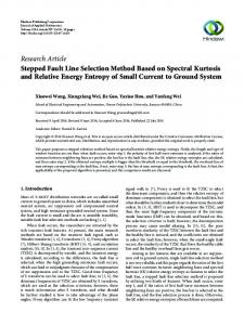
As shown in Figure 2, it is assumed that a permanent fault of A-phase occurs between the switches D, H and I. Through the PSCAD simulation system, the three-phase simulation current waveform of substation outlet switch S1 is shown in Figure 3. The horizontal axis is time, the unit is s; the longitudinal axis is current, and the unit is A.
ACSL S1, A, B, D It can be seen that the fault occurs in the minimum failure determination area where the switch D is the parent node. According to the formulas (1), (2) and Table.1, it can be seen that the area where the ground fault occurs is the minimum fault judgment area Area4.
5 Conclusion According to the above analysis, it can be seen that in the non-solid-earthed distribution network, when the singlephase grounding fault occurs, the current in the upstream fault phase is abruptly changed due to the superposition of the normal load current and the capacitance current,
Figure 3. The three-phase current simulation waveform.
4
MATEC Web of Conferences 160, 01007 (2018) https://doi.org/10.1051/matecconf/201816001007 EECR 2018 EECR 2018
and the current in the downstream fault phase will keep the load current constant. For other non-fault phase and non-fault feeder current in the upstream or downstream of the fault point, the steady-state current values are load current without mutation. A single-phase grounding fault judgment method based on mutation current logic matrix is proposed. Then the single-phase grounding fault can be determined in the minimum fault judgment area of the last element of the mutation current logic sequence list as the parent node. This method is also applicable to the non-solid-earthed distribution network containing distributed generation. The simulation results show that the method proposed in this paper has a good adaptability to the permanent grounding fault and it is worth popularizing.
7.
8.
9.
10.
References 1.
2.
3.
4.
5.
6.
Zhang Guping, Jiang Chao, Li Gang. Method of Fault Area & Section Location for Non-solidly Earthed Distribution System. Proceedings of the CSEE. 32 (2012) Chen Bobo, Qu Weifeng, Yang Hongyu, etal. Research on single phase grounding arc model and line selection for neutral ineffectively grounding system. Power System Protection and Control. 44 (2016) Lai Ping, Zhou Xiangling, Qiu Dan. Research on transient-current frequency analysis and faulty line detecting method in indirectly grounding power system. Power System Protection and Control.43 (2015) Chen Kui, Wei Xiaoguang, Chen Jingbo,etal. Fault Line Detection Using Sampled Data Processing and adaboost for Small Current Grounding System. Proceedings of the CSEE.34 (2014) Yang Jianxiang, Chen Zhongxue, Dou Minna. A novel frequency band self-adaptive selection method of fault line selection in distribution network.Power System Protection and Control.43 (2015) Yan Feng, Yang Qixun, Qi Zheng, etal.Study onfaultlocation for distribution network based on travelling wavetheory.Proceedings ofthe CSEE.24 (2004)
11.
12.
13.
14.
15.
5
Wu Lepeng,Huang Chun,Lin Dabin,etal.Faulty line selection based on transient wavelet energyfor non-solid . earthed network . Electric Power Automation Equipment.33 (2013) Liu Mouhai, Fang Tao, Jiang Yun,etal . A new correlation analysis approach to fault line selection based on transient main-frequency components.Power System Protection and Control. 44 (2016) Ma Shicong,Xu Bingy in,Gao Houlei.An earth fault locating method in feeder automation system by examining correlation oftransient zero mode currents . Automation of Electric Power Systems. 32 (2008) Xue Yongduan, Li Juan, Xu Bingyin . Transient Equivalent Circuit and Transient Analysis of Singlephase Earth Fault in Arc Suppression Coil Grounded System.Proceedings of the CSEE. 35 (2015) Gao Zhipeng, Zhang Huifen, Sun Xuna.A method of fault line selection and fault point location with halFwave DC injection in distribution network.Power System Protection and Control. 41 (2013) Zhang Huifen, Pan Zhencun, Sang Zaizhong.Injecting current based method for fault location in neutral isolated power system.Automation ofElectric Power Systems. 28 (2004) Wu Jun , Lu Gang . Virtual grounding identification technology in neutral point noneffectively grouned system . Power System Protection and Control. 38 (2010) Sun Yongchao, Tai Nengling, Zheng Xiaodong. Research on single-phase grounding fault location of distribution network with DG. Journal of Electric Power Science and Technology. 31 (2016) Guo Liwei, Xue Yongduan, Zhang Linli,etal. Analysis of Single-phase Earth Fault in Low Resistance Grounded Distribution Network Containing DG. Automation of Electric Power Systems. 39 (2015)