Electromagnetic Interference. Yu-ichi Hayashi ... tion method based on intentional electromagnetic interference. (IEMI) ... noise in the field of EMC (Electromagnetic Compatibility) and, many ..... publications/fips/fips197/fips-197.pdf, Nov. 2001.
Non-invasive Trigger-free Fault Injection Method Based on Intentional Electromagnetic Interference Yu-ichi Hayashi, Naofumi Homma, Takeshi Sugawara, Takaaki Mizuki, Takafumi Aoki, and Hideaki Sone Tohoku University, Aramaki Aza Aoba 6-6-5, Sendai 980-8579, Japan
Abstract—This paper presents a new type of fault injection method based on intentional electromagnetic interference (IEMI), which causes information leakage from cryptographic devices without disrupting their operations or damaging their physical structures. The basic principle is to transmit a sinusoidal EM wave via a power/communication cable or an antenna. The IEMI-based fault injection method is performed at a distance from the target module through many filtering components, such as a voltage regulator, without leaving any hard evidence of the attack. It can also be applied under the condition that there is no trigger signal synchronized with the cryptographic operation. We demonstrate the potential capability of the IEMI-based fault injection attacks through an experiment using an Advanced Encryption Standard (AES) module implemented on a standard FPGA board. The experimental result shows that generating effective faults is feasible and such IEMI-based fault injection is available for a typical differential fault analysis on AES. Keywords-fault injection attacks; intentional electromagnetic interference; AES; non-invasive fault injection
I. I NTRODUCTION Fault injection attacks are attracting much attention in the field of cryptographic devices: electronic devices implementing a cryptographic module in software or hardware [1]. Attackers first inject faults to cryptographic operations and then estimate secret information from several faulty ciphertexts. Until now, many variations of fault injection attacks and countermeasures have been presented and newer ones are still being proposed [2]. The target includes relatively-larger electronic devices and systems as well as handy devices such as smartcards and mobile phones. With the advance of such attacks and countermeasures, fault injection methods have also been investigated in order to evaluate their possibilities. Various injection methods were reported using glitches on power and clock signals, lower voltages, higher frequencies, optical emission, laser shots, electromagnetic (EM) pulse, and so on. The conventional injection methods are basically invasive to cryptographic modules or devices. For example, optical emission and laser shot require to depackage a cryptographic module and work very close to the module surface. Such methods are sometimes able to cause local faults which are available for more powerful attacks. On the other hand, hard evidence, such as depackaging, and close access to the module are unavoidable. Lower voltage (or under-power)
and higher frequency (or over-clocking) do not require any damage to the cryptographic module and cause setuptime violation faults. However, these injection methods are usually assumed to access and modulate a power supply voltage or an oscillator on the target device. Setup-time violation faults can also be caused by a glitch, a sudden change in clock signal. The glitchy-clock signals can be synchronized with a cryptographic operation and thus are effective for injecting faults timely. On the other hand, the glitch injection is limited to a specific condition that attackers have enough accessibility and controllability to the device. Thus, a simple countermeasure to prevent direct access and invasion would be effective for such conventional methods. In this paper, we present a new type of fault injection method based on intentional electromagnetic interference (IEMI), which causes temporal faults to cryptographic devices at a certain distance via an attached cable without any invasion or modification to the devices. Previous studies shows that EM fault injections using high-voltage pulses offer non-invasive attacks. However, the use of such EM pulse requires close access to the cryptographic module even if the pulsating square wave has a high voltage of about 100 V. The basic idea of the presented IEMI is to transmit a sinusoidal wave of a specific frequency which has a higher transfer ratio to the cryptographic module. This kind of IEMI can be a severe threat to many electrical systems with cryptographic devices even if the devices are equipped with countermeasures against direct access and invasion. This paper shows the first demonstration of such IEMIbased fault injection attack through an experiment using an Advanced Encryption Standard (AES) module implemented on a standard evaluation board. Temporal faults are injected via a power cable attached to the board. We confirm that generating effective faults only to the cryptographic module is feasible. The result indicates that such IEMI-based fault injection would be available for attacking common electrical devices and systems, which usually have lower tolerance to noise as compared with the evaluation board. II. FAULT INJECTION METHOD BASED ON IEMI Problems of electromagnetic interference (EMI) are major concerns for researchers and designers of electrical circuits.
-20
-55 10
Attenuation [dB]
Attenuation [dB]
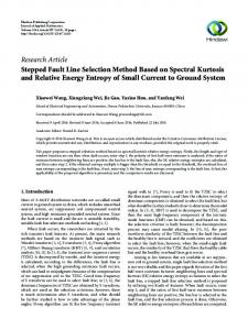
EMI is usually recognized as a disturbance that affects an electrical circuit due to either conducted emission or radiated emission from other devices. Such EMI has been studied as noise in the field of EMC (Electromagnetic Compatibility) and, many studies on noise suppression or reduction have been conducted in order to protect own or other electronic devices. As a result, some EMC-related committees, such as FCC [3], have sets standards for radiated and conducted EMI immunity and their own voluntary compliance programs. Current electronic devices are usually designed so as to satisfy these EMC standards. Devices in conformity with the standards are expected to be immune against EMI. EMI can also be used intentionally such as radio jamming. The above standards mainly cover unintentional EMI but not Intentional EMI (IEMI), which is defined as ”Intentional malicious generation of electromagnetic energy introducing noise or signals into electric and electronic systems, thus disrupting, confusing or damaging these systems for terrorist or criminal purposes” [4],[5]. There is no strict standard covering such IEMI for now. According to the background, many studies have been conducted for the classification of IEMI waveforms, the test capabilities to generate waveforms, and the understanding of the IEMI effects on equipment, systems, communications, and measurements. IEMI is usually meant to damage or destroy electronic devices permanently. When intentional EM field is applied to fault injection attacks, the major concern is whether temporal faults can be injected only onto a cryptographic module while the operations of all other modules in the device work without any damage. This kind of fault injection has never been studied even in the research field of IEMI. The fault injection presented here is a new type of IEMI which causes such temporal faults to cryptographic devices. Here, we focus on a phenomenon that a noise is transmitted to components on an electric device via an attached cable. The effect of such noise in frequency domain, which is called the transfer function, is different for each component. The transfer function changes with the location and the arrangement of the components [6]. We employ the difference between transfer functions for different components. Fig. 1 illustrates an image of the IEMI-based fault injection, where a cryptographic module is mounted on a common device (i.e., a PCB board) equipped with a twistedpair power cable. In this example, the decrease rate of a frequency finj is lower than those of other frequencies in the transfer function to the cryptographic module, while the decrease rate of finj is not lower than those of other frequencies in the transfer functions to other modules. If a sinusoidal wave of the frequency finj is transmitted to the device, a disruption can be selectively introduced into the cryptographic module. Also, although a sinusoidal wave of another frequency can be transmitted to the cryptographic module, in this case the wave can induce a fault into other modules with high probability. Thus, the IEMI-based fault
f inj 100 Frequency [MHz]
Another module Cryptographic module
finj
finj
Injection
-20
-55 10
f
inj 100 Frequency [MHz]
finj
Injection probe DC
Power supply finj
finj
System GND
finj
Signal generator
Figure 1.
Image of fault injection based on sinusoidal EM wave.
injection involves the transmission of a sinusoidal wave of an effective frequency, such as finj , through an attached cable. From a practical point of view, attackers would increase the noise level gradually and scan a frequency band including finj while observing if any fault is generated in the output. It is rather easy to identify a voltage and a frequency effective for the fault injection. The above method fluctuates the electric potential of VDD/GND inside the module and then generate temporal faults. Such faults would be similar to those obtained by over-clocking and under-power methods. Glitchy clock signals would also be generated if there is an effective frequency transmitted to an oscillator. III. E XPERIMENTS A. Setup Fig. 2 shows an overview and a block diagram of the fault injection setup, where SASEBO-G is used for the test device. Note here that due to the relatively-larger VDD and GND planes, SASEBO-G has a higher immunity (or tolerance) to EMI as compared with common electronic devices having the same board size. An AES circuit supporting 128-bit key length is implemented in an FPGA on SASEBO-G. The circuit uses a loop architecture, where one round is processed every clock cycle [7]. A single encryption operation takes 11 clock cycles for the ten cryptographic rounds and one additional clock cycle for data I/O. The clock frequency and the supply voltage on SASEBO-G are 24 MHz and 3.3 V, respectively. The secret key is a reference value (0x2b7e151628aed2a6abf7158809cf4f3c), as given in the algorithm specification [8]. Sinusoidal waves are generated by a signal generator (MG3641A), after which they are amplified by an amplifier (ZHL-2-12). Finally, the sinusoidal waves are introduced via an injection probe (FCC F-140) into a power cable attached to SASEBO-G. The injection probe is commonly used for testing the immunity of various devices to noise, such as the Bulk Current Injection test. We locate the injection probe about 60 cm away from SASEBO-G. In order to observe
-10 Oscilloscope (MSO6104A)
PC
Trigger Clock (24 MHz)
SASEBO-G FPGA 1
RS232C Clock (24 MHz)
FPGA 2
Bus
PC
GPIB
1.5 V
1.5 V
Regulator 3.3 V
Regulator 3.3 V
Signal generator
-20
Power supply
-30
RS232C level converter
SASEBO
Amplifier (ZHL-2-12) +25 dB
Power line
Injection probe (FCC F-140)
Amplifier
24 V DC
Oscilloscope
DC
DC
Attenuation [dB]
Synthesized signal generator (MG3641A)
250 MHz 170 MHz
Clock FPGA1
-40 -50 -60
180 MHz
-70 -80
Injection probe Power supply Power supply
Power supply
Figure 2.
-90 Experimental setup.
the VDD/GND fluctuations of the AES module, we employ an oscilloscope (MSO6104A) and monitor them at the point between the FPGA1 GND pin and the GND line. We observe how the introduced sinusoidal wave affects the original wave during the AES operation. B. Fault injection Fig. 3 shows the transfer functions from the above injection probe to the observation points of the clock and FPGA components. We confirmd that the transfer function for the FPGA has the lowest decrease rate at around 170 MHz and 250 MHz, while that for the clock component has the lowest decrease rate at around 100 MHz, 200 MHz and 250 MHz. This result shows that the transfer functions can be rather different for points situated merely a few centimeters away from each other. In this experiment, we select a specific frequency band and inject sinusoidal waves in the frequency band with about 5 V. It might be possible to induce faults by a pulsating square wave composed of a wide range of frequencies (e.g., a wave generated by an ESD gun) with a much higher voltage (e.g., 10-1000 V). However, such high-voltage signals would damage some of the components inside the device, and therefore such invasive IEMI-based attack would pose a less threat from the viewpoint of information leakage. According to Fig. 3, we employed sinusoidal waves with a frequency of 170 MHz. The fault injections are performed at arbitrary timing during continuous AES encryptions with different plaintexts generated at random. Note that we do not employ any precise trigger signal for practical reasons. We assume here that attackers can obtain faulty outputs during the fault injection. The faulty outputs (i.e., ciphertexts) are stored to a PC in this experiment. We calculate the true outputs separately and check what kinds of faults occur in the module by the difference between the corresponding true outputs and the faulty ones. Fig. 4 shows two voltage waveforms with and without fault injection observed at the FPGA during an AES operation, where the encryption process starts at around 250
50 100 150 200 250 300 350 400 450 500 Frequency [MHz] Figure 3.
Transfer functions.
ns and finishes after 11 clock cycles. There are 11 peaks in each of the waveforms. This implies that the encryption itself works in the module. Compared with the original waveform, the faulty waveform fluctuated widely in the range of approximately 400 mV. In this experiment, we observed faulty outputs by sinusoidal waves of 4.0 V to 5.5 V, which can be generated easily by a combination of off-the-shelf equipment. The transfer function for the clock component in Fig. 3 also shows a relatively-lower decrease rate at 170 MHz; however, the clock generator did not fail even when the maximum sinusoidal wave of 5.5 V was introduced. If a selected frequency affects other components, other possible frequencies would be selected. In the case shown in Fig. 3, we can select an alternative frequency at around 300 MHz. The result shows that a sinusoidal EM wave can cause faults with a certain probability during a large number of encryption operations if the voltage and frequency are properly selected. If this method is applied to other common devices with lower immunities or untwisted pair cables, the effective ranges of injection voltage and frequency would be expanded. Also, we can easily extend the distance from the injection probe to the target module by increasing the amplitude level. Note here that the faults occurred via a power cable through many filtering components including DC-DC converters and voltage regulators. This implies that this method has a potential of injecting faults beyond an external power supply (i.e., an AC-DC converter). Such extension of the IEMI-based fault injection would be investigated in the future study. C. Differential fault analysis on AES: Case study The faults obtained in the above experiment can be used in actual fault injection attacks on AES modules. There are several types of differential fault analyses applied to AES modules. In this paper, we focused on a typical attack proposed by Piret et. al.[9] as an example.
Original waveform Fault-injected waveform
50 mv 100 ns
Figure 4. operation.
Original and fault-injected waveforms observed during AES
Piret’s attack requires 1-byte faults to be injected precisely at the 8th or 9th round of the AES operation. In [9], the timing was adjusted by a fault injection technique synchronized tightly with the AES operation. On the other hand, our IEMI-based fault injection was not synchronized with cryptographic operations since it is assumed to be performed at a certain distance from cryptographic modules. Therefore, sinusoidal waves were freely generated at every 10 ms in this experiment. This kind of asynchronous fault injection causes a variety of faults in all ten rounds. Therefore, there is an additional challenge to identify faults, whose types, timings and availabilities are unknown, in order to implement IEMIbased fault injection attacks. Faults injected at the input of the 9th round can be identified by the comparison of true outputs with the faulty ones. The position (or index) of the faulty bytes directly shows whether a fault is present on not. More precisely, it is possible to determine whether a 4-byte fault corresponds to the inverse ShiftRows operation since a 1-byte fault at the 9th round is always expanded to a specific 4-byte fault at the output. Even if two or more faults occurred by a single injection, it is possible to detect them by an exhaustive search of all the 16 key candidates. Faults at the input of the 8th round are not easily identified by such exhaustive search since all 16 bytes in the output include faults. However, it would be possible to obtain them by the effective search methods proposed in [10]. As a result, the IEMI-based method generated 13,497 faulty outputs, which are available for Piret’s attack, out of 340,000 encryptions. We found faulty outputs by the above technique for both attacks at the 8th and the 9th rounds and confirmed that the 16-byte secret key was completely revealed from them. Note here that there is another possibility of applying other attacks to a large number of other faulty outputs. The important point here is that the IEMI-based fault injection generated effective faults and showed a definite possibility of attacking existing electrical devices and systems at a certain distance even if they equip countermeasures against direct access and invasion.
IV. C ONCLUDING REMARKS This paper introduced a new type of fault injection method based on IEMI that causes information leakage from cryptographic modules without disrupting their entire operations. A differential fault analysis attack has demonstrated through an experiment using an AES module implemented on a SASEBO-G board. We confirmed from the experimental result that generating effective faults is feasible at 60 cm away from the module without using any precise trigger signal. Although we employed an injection probe attached to a power line in this experiment, it would be possible to use other injection methods. For example, the use of an antenna is also possible if the transfer function from the module to the antenna can be derived. A further investigation is required for developing effective countermeasures of such IEMI-based fault injection. R EFERENCES [1] D. Boneh, R. Demillio, and R. Liotin, “On the importance of checking crypto-graphic protocols for fault,” EUROCRYPT 1997, Lecture Notes in Computer Science, vol. 1233, pp. 37– 51, May 1997. [2] H. Bar-El, H. Choukri, D. Naccache, M. Tunstall, and C. Whelan, “The sorcerer’s apprentice guide to fault attack,” IACR ePrint archive, vol. Report 2004/100, pp. 1–13, May 2004. [3] “Federal Communications http://www.fcc.gov/
Commission
(FCC),”
[4] IEC SC77C, High Power Electromagnetic (HPEM) Effects on Civilian Systems, IEC Document 61 000-1-5 Working Draft, Mar. 2002. [5] W. Radasky, C. Baum, and M. Wik, “Introduction to the special issue on high-power electromagnetics (HPEM) and intentional electromagnetic interference (IEMI),” IEEE Transactions on Electromagnetic Compatibility, vol. 46, no. 3, pp. 314–321, Mar. 2004. [6] R. C. Paul, “Introduction to electromagnetic compatibility,” Wiley-Interscience, 2006. [7] Cryptographic Hardware Project, http://www.aoki.ecei.tohoku.ac.jp/crypto/. [8] National Institute of Standards and Technology (NIST), “Advanced Encryption Standard (AES) FIPS Publication 197,” http://csrc.nist.gov/ publications/fips/fips197/fips-197.pdf, Nov. 2001. [9] G. Piret and J. Quisquater, “A differential fault attack technique against SPN structures, with application to the AES and Khazad,” CHES 2003, Lecture Notes in Computer Science, no. 2779, pp. 77–88, Sep. 2003. [10] S. Gomisawa, Y. Li, J. Takahashi, T. Fukunaga, Y. Sasaki, K. Sakiyama, and K. Ohta, “Efficient differential fault analysis for AES,” IACR Cryptology ePrint archive, vol. Report 2010/336, pp. 1–12, Jun. 2010.